Week 1 Spur Gear Challenge
AIM: To perform static structural analysis on a pair of spur gears made of various materials in order to calculate equivalent stress, total deformation, and stress intensity and compare the findings.
OBJECTIVE:
i. To conduct static structural analysis on a pair of spur gears made of cast iron (ductile) and determine equivalent stress, total deformation, and stress intensity.
ii. To carry out the identical analysis with Cast Steel as the material.
iii. Using Cast Bronze as the material for the analysis.
iv. To learn about what stress intensity is and Find the location for possible fracture
SPUR GEARS (Theory)
A gear is a rotating machine part having cut teeth, or cogs, which mesh with another toothed part in order to transmit torque. Two or more gears working in tandem are called a transmission and can produce a mechanical advantage through a gear ratio and thus may be considered a simple machine. Geared devices can change the speed, torque, and direction of a power source. The most common situation is for a gear to mesh with another gear; however, a gear can also mesh with a non-rotating toothed part, called a rack, thereby producing translation instead of rotation.
The gears in a transmission are analogous to the wheels in a pulley. An advantage of gears is that the teeth of a gear prevent.
The simplest sort of gear is a spur gear. They are made up of a disk or cylinder with radially projecting teeth. The edges of each tooth are straight and parallel to the axis of rotation, despite the fact that the teeth are not straight-sided (they are often of specific form to produce a constant drive ratio, primarily involute but less frequently cycloidal). These gears will only mesh properly when mounted to parallel shafts. The tooth loads do not produce any axial thrust. Spur gears perform admirably at medium speeds but are typically loud at high speeds.
Either the involute profile or the cycloidal profile is used to create spur gear teeth. The majority of gears are produced using involute profiles with a 20° pressure angle.
When two gears are in mesh at one instant there is a chance to mate the involute portion with a non-involute portion of mating gear. This phenomenon is known as "Interference" and occurs when the number of teeth on the smaller(pinion) of the two meshing gears is less than the required minimum.
Undercutting can be used to prevent interference, however, this is not a good option since it weakens the tooth at the base. Here, corrected gears are employed. The cutter rack is moved up or down in corrected gears.
There are two basic divisions for spur gears: external and internal. External gears are those that have their teeth cut out from the cylinder. Internal gears are gears that have teeth carved into them on the inside of the cylinder. When two external gears mesh together they rotate in opposite directions. An internal gear can only mesh with an external gear and the gears rotate in the same direction.
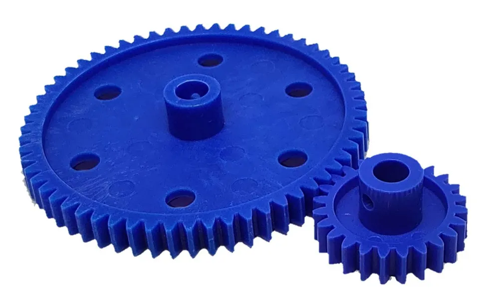
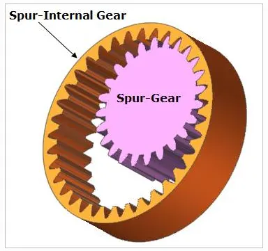
FIG: SPUR GEAR
3D Modelling SET-UP
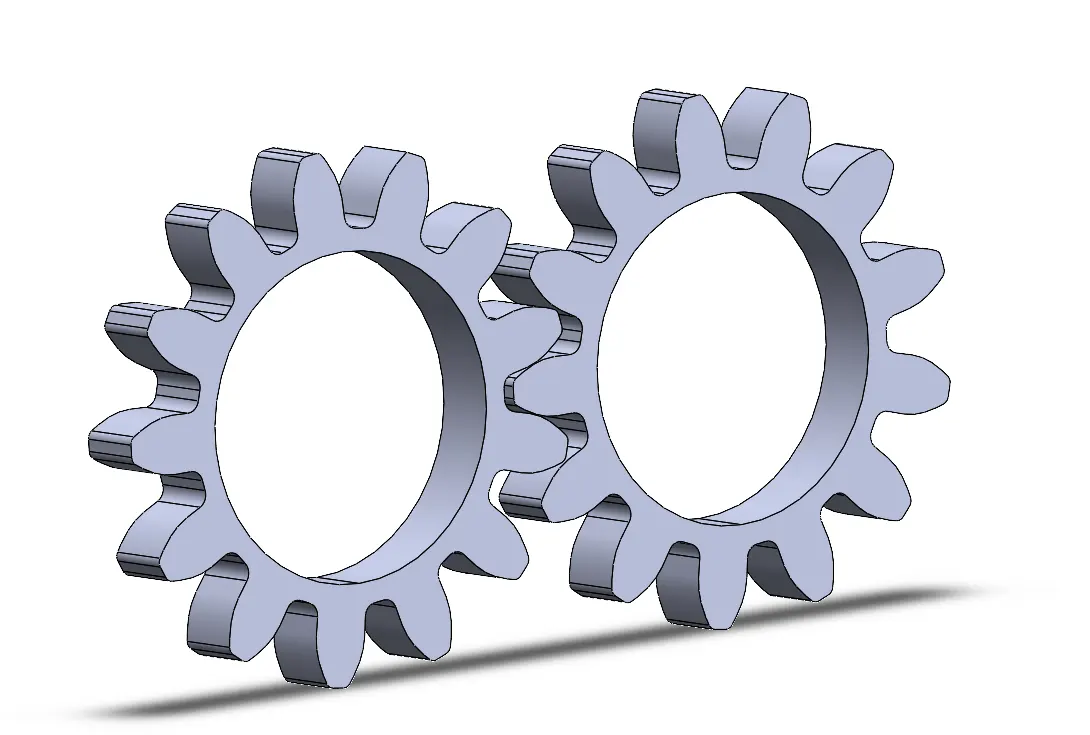
Figure 1.1: Spur gear for simulation (.stp)
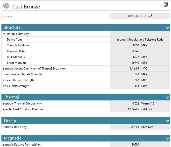
MATERIAL PROPERTIES
PROCEDURE:
- Get static structure from the analysis system.
- in Engineering data select Granta Sample Materials.
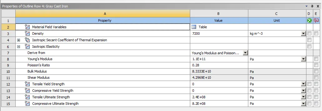
- From the material list, add material Cast iron(Ductile), Cast steel, or Cast Bronze as per case to be analyzed.
1. CAST IRON (DUCTILE)
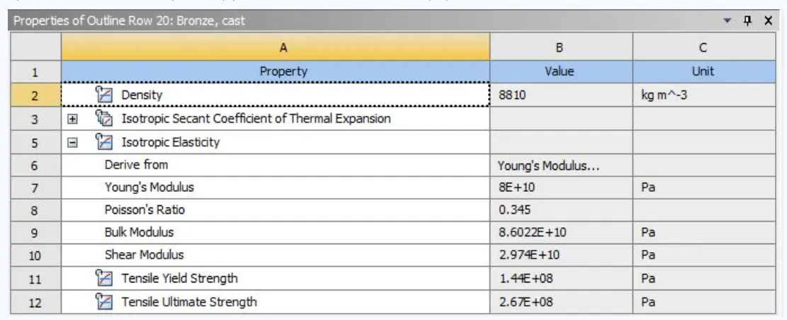
2. CAST BRONZE
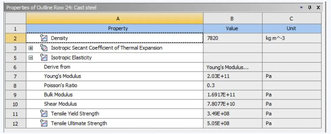
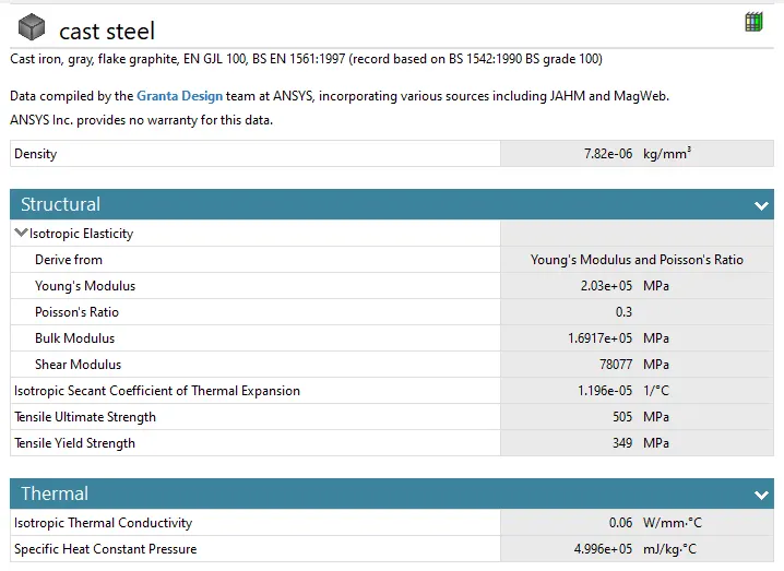
3. CAST STEEL
CASE_1 (CAST IRON DUCTILE)
Cast iron are metal that has very low melting points with carbon content alloy greater than 2%. The ductile type has properties that have graphite grains that stop cracks from propagation, unlike grey cast iron which deflects and initiates cracks through the material. Also, there is white cast iron which allows the propagation of cracks through them.
- Start a new Static Structural project.
- Go to Engineering Data, select the CAST IRON DUCTILE material, and click on the ADD to add the material to the project.
- The other two materials, if not present in the Engineering Data Sources, must be manually added to the project. The properties of the two materials are added from the data supplied in the problem, as shown above for CASE 1 .
- Add the Cast iron material to the library and Update the cast iron material to the System, under the Engineering data.
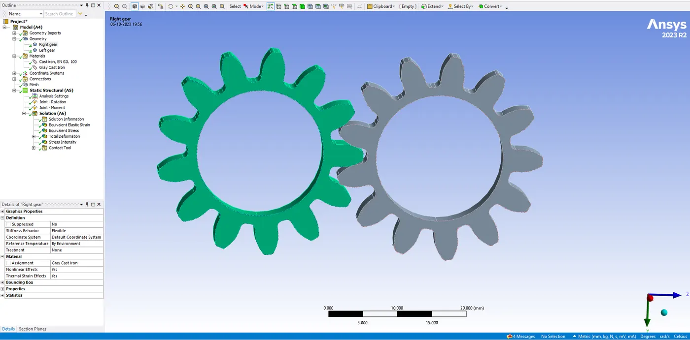
- Under geometry import the spur gear model.
- Rename the two gears as LEFT and RIGHT to the respective gears
Contacts
- From the project tree, select “Connections” and create “Contacts”.
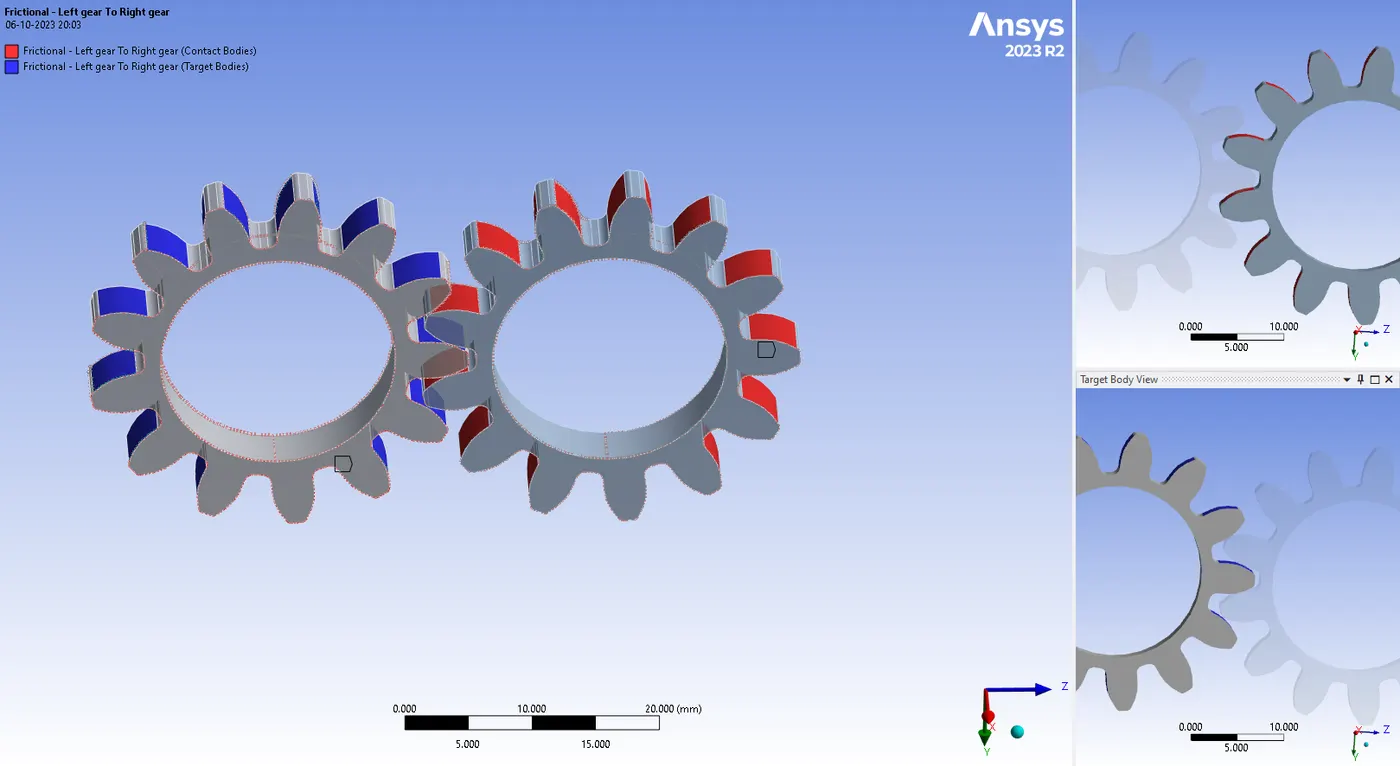
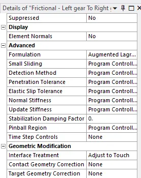
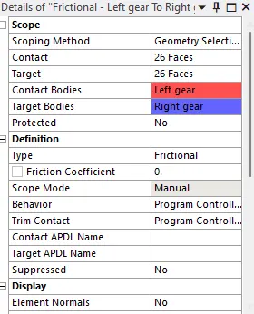
- For defining contacts between two gears, select the faces of the left gear as contacts and the faces of the right gear as Targets for connection.
- There are 26 faces of each gear must be selected.
- Select contact type = Frictional. because due to friction, there will be movement between gears.
- Select behavior = symmetric
- Select formation = Augmented Lagrange. As soon as teeth come in contact, they will tend to move from the position so Augmented Lagrange formation reduces vibration/ chatter and penetration stiffness of gears.
- Select interface Treatment = Adjust to touch because if there is a gap between them or initial penetration then this setting will help to adjust it and any error can be avoided.
- Select the inner face of each gear and give it a revolute joint as described in the below image.
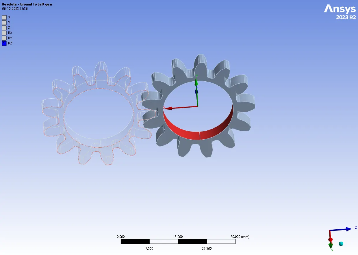
Insert revolute joints for the gear in order to revolute about their axes. So click on connections go to insert and select joint. select the body to ground option, type as revolute, and select the inner face of the gear for reference. Follow the same method for another gear.
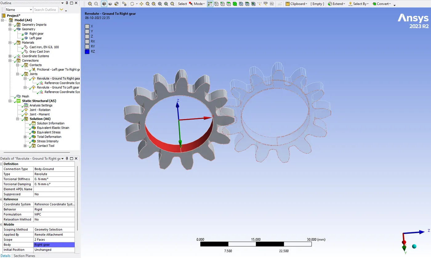
- We can see that in the revolute joint, the Degree of freedom for gears is automatically set to its axis or in RZ direction.
Mesh Details:
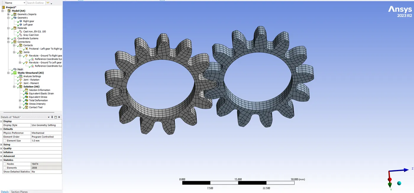
In ANSYS automatic mesh will be performed with the Default mesh size and the mesh size we chose as 1mm. with hexahedron mesh as depicted below along with total number of nodes and elements
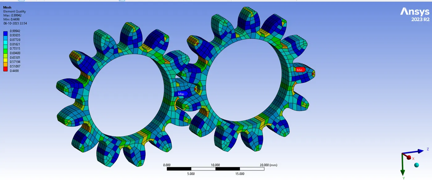
- The figure below shows the element quality of the mesh and from the legend, it is clear that the maximum element quality has been attained with 0.99 and a minimum quality of 0.44 at the tip of the tooth but we are mainly concerned about the quality at the root of the teeth where interference will be maximum
BOUNDARY CONDITIONS:
- Here we are going to look at contact forces, traces, and stress developed for 1 revolution of gear. So for 180 degree angle in the analysis setting give values as given below
No steps = 6
Auto time Stepping = ON
Defined by = TIME
initial Time Step = 0.2 s
Minimum Time Step = 5 e-2 s
Maximum Time Step = 0.5
- Select all 6 steps and select Large Deflection = ON in Slover controls. other Bountry conditions for joint are as given below
- joint load
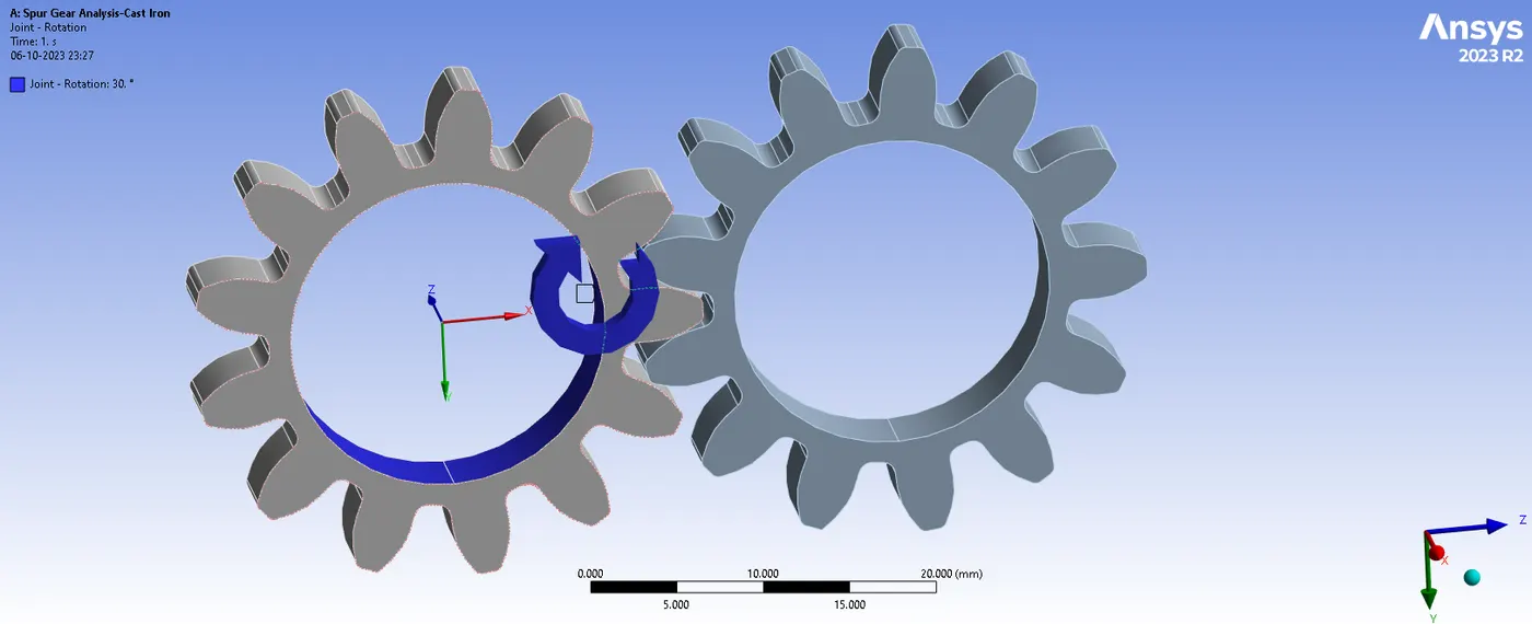
Joint Rotation = Ground To Left
Type = Rotation
Magnitude = Tabular Data
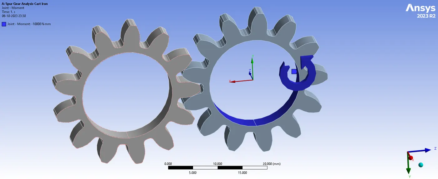
The left gear will have clockwise rotation movements while the right side will face anticlockwise moments
Now define the joint load for both the gears. so click on the static structural and select joint load, change the type as rotation for one gear, and assign the rotational value in the table from 0, 30, 60, 90, 120, 150, 180. Then similarly insert the joint load change the type to moment for rest of gear and assign the moment as 10Nm.= 10000Nmm in the opposite direction for anti-clockwise movements as shown below images
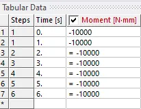
- Now request the outputs such as equivalent stress, equivalent elastic strain, total deformation, and stress intensity.
- To achieve this, right-click on Solution, pick Insert, then Deformation, and finally choose the Total option. Similar to this, choose Equivalent from the Stress option to add Equivalent Stress to the solution, and then choose Intensity to add Stress Intensity.
- Also, give Contact Tool and create solutions for contact “Status” and “Pressure”.
- POST PROCESSING:
After successful completion of analysis for the Cast Iron Ductile, the material assignment is changed and the analysis is re-run for the new material until results for all materials are obtained.
Material assignment can be changed by clicking on Geometry and selecting the LEFT gear and then in the Materials section go to Assignment and change the material from CAST IRON DUCTILE to CAST STEEL. Similarly, do the same for the RIGHT gear and the rest of things remain the same and the analysis is performed. The same thing is done to change the material to CAST BRONZE.
Also you can make separation of one other material and re-run the analysis, although the other set ups are same.
RESULTS CASE 1: (CAST IRON)
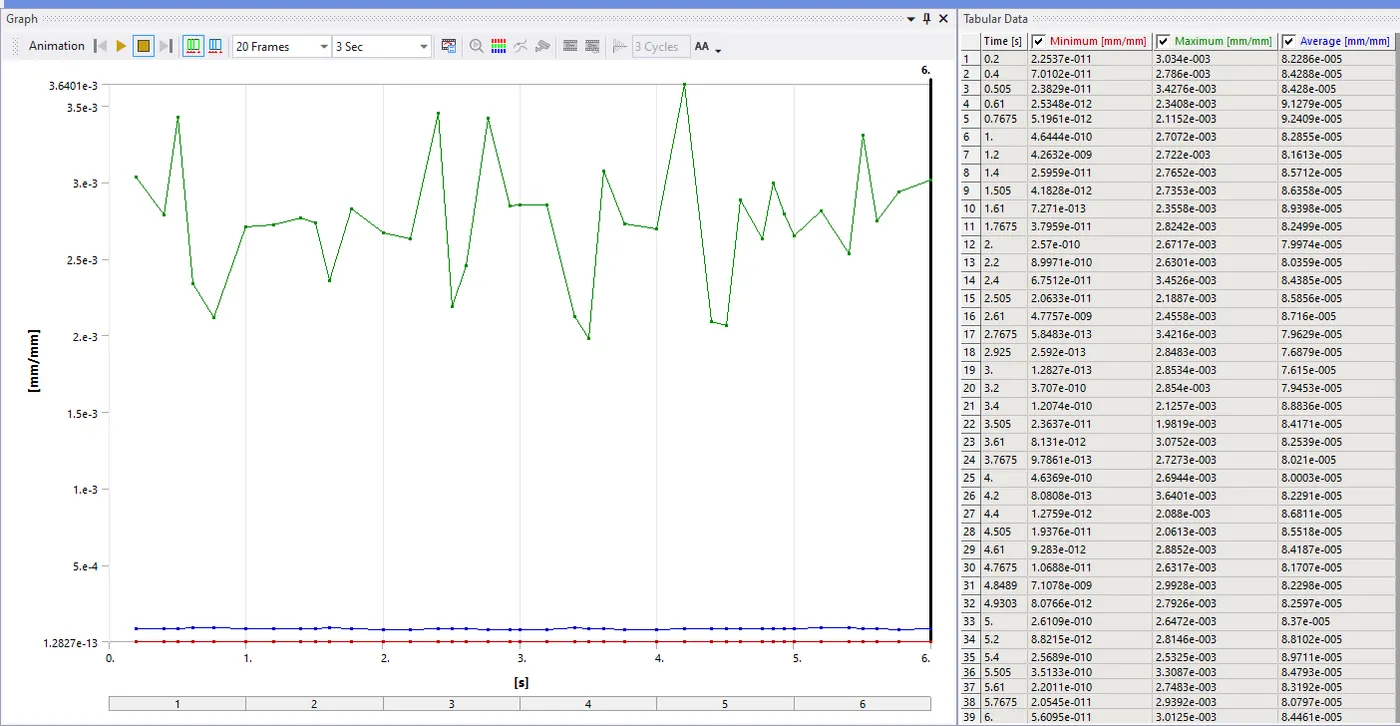
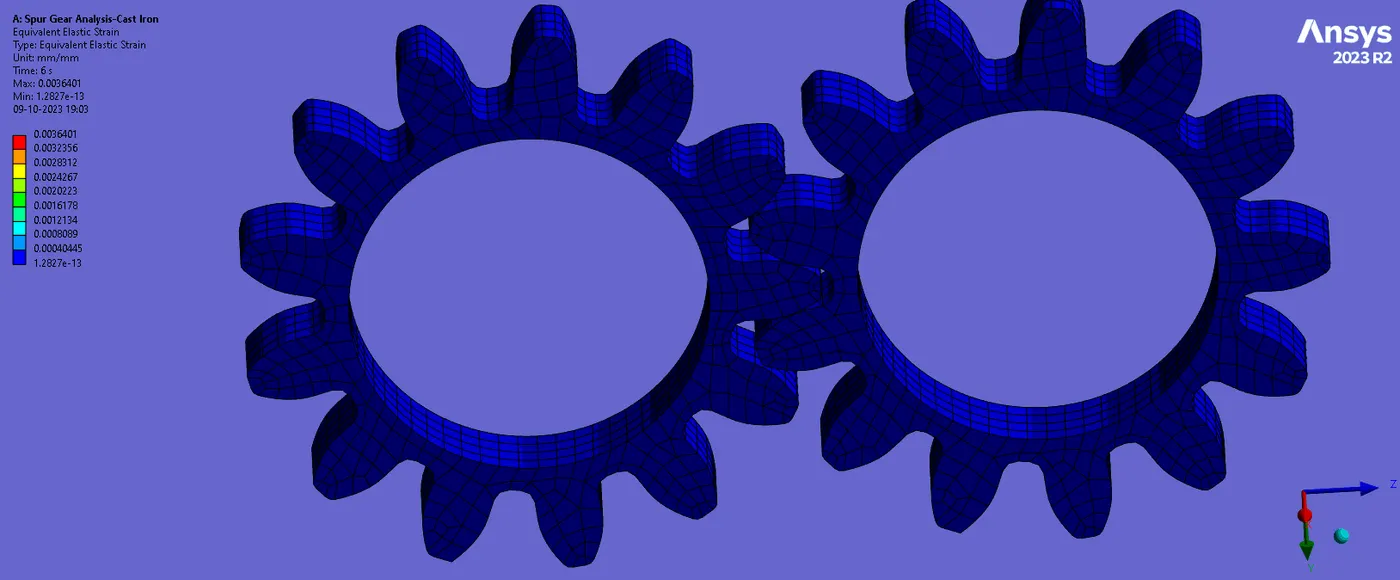
Equivalent Strain
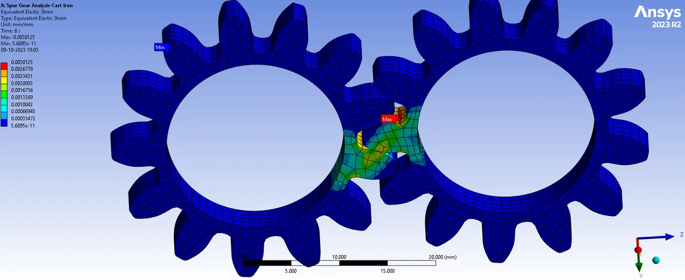
The maximum strain observed in the tooth of the gears where interference is there as shown above
Equivalent Stress:
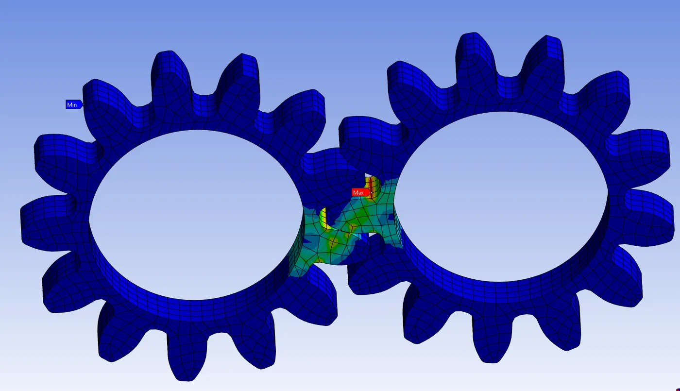
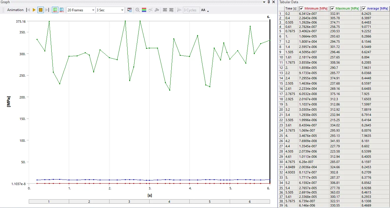
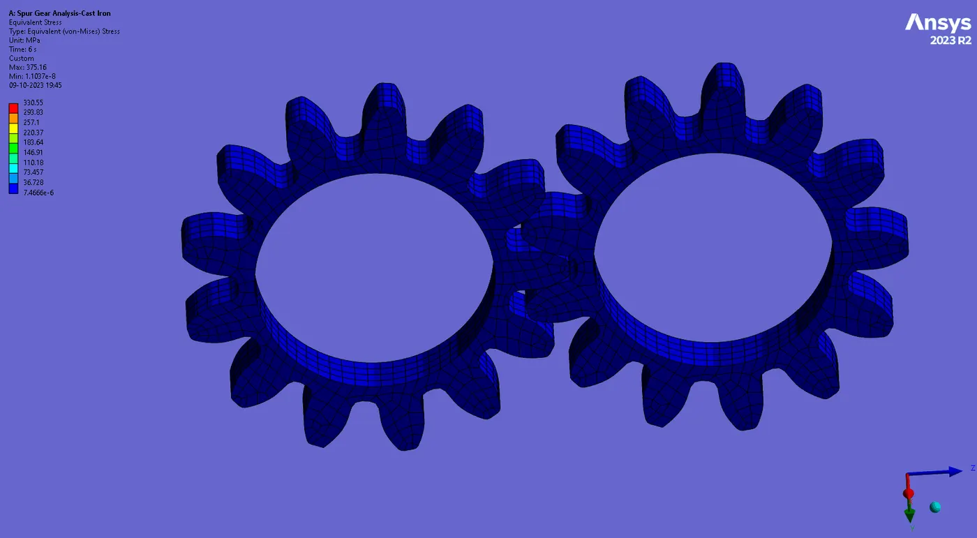
The maximum stress was observed same at the root of the tooth where interference between 2 mating gears will be maximum @ 331 MPa
Total Deformation
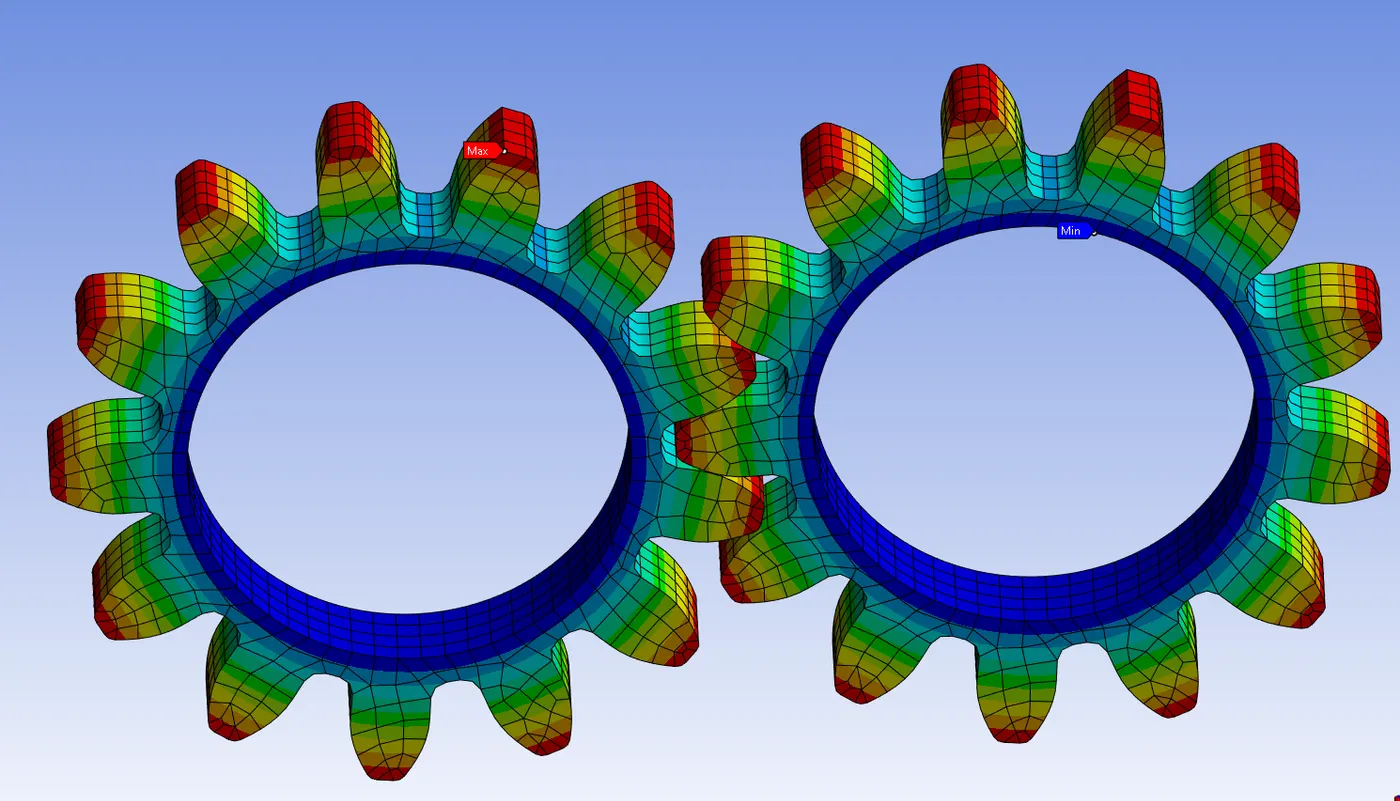
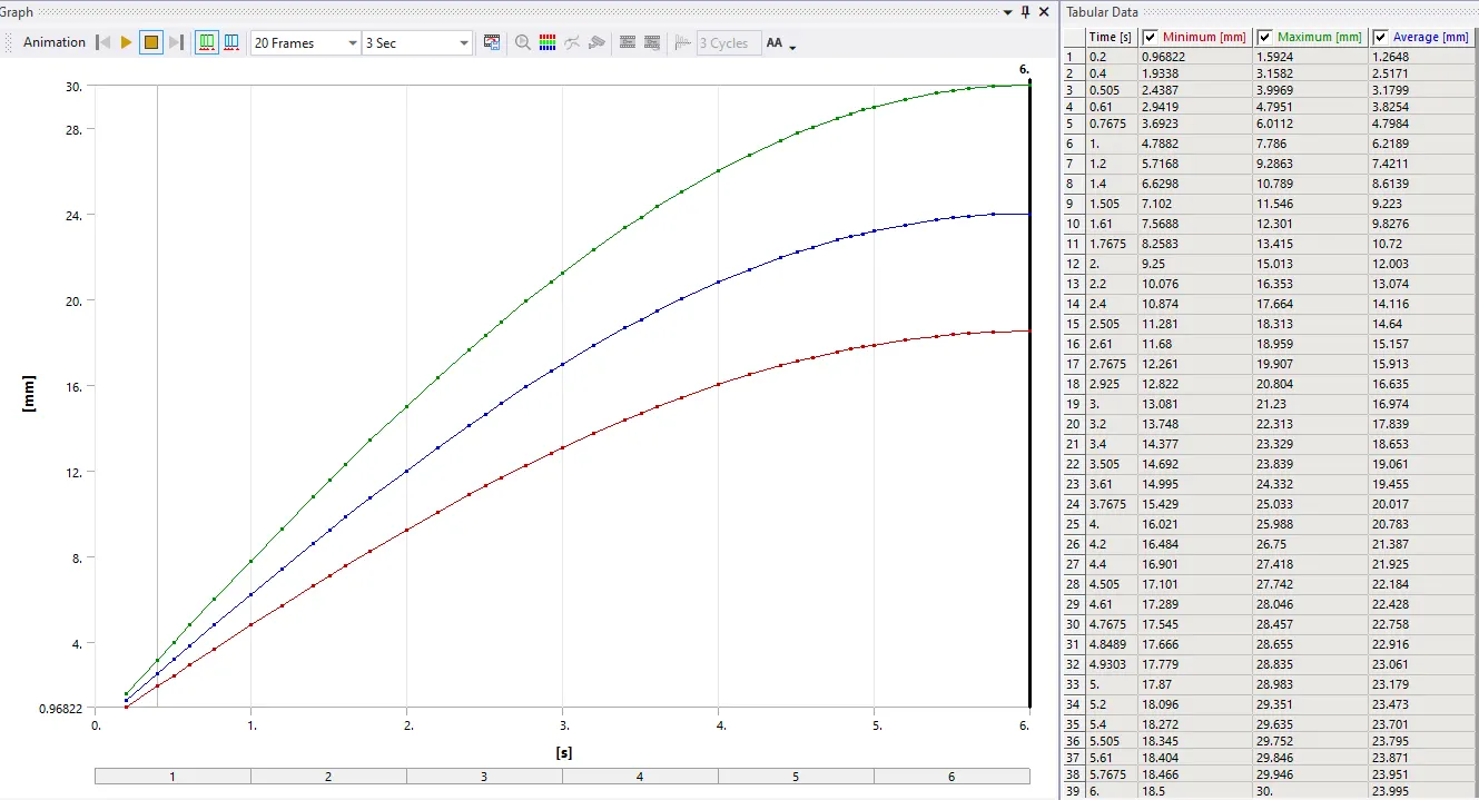
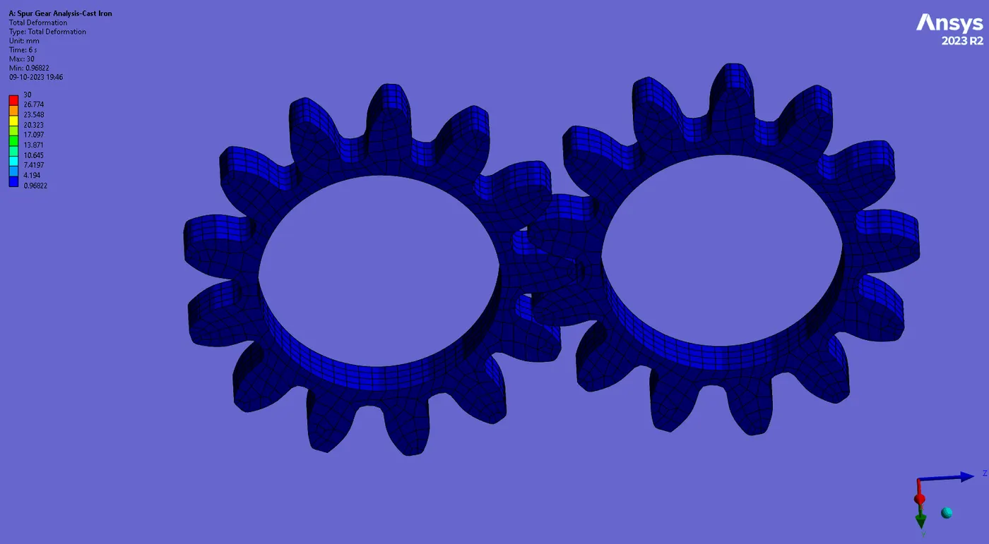 The maximum Deformation was observed same at the end of the tooth where interference between 2 mating gears will not be maximum @ 30 mm
Stress Intensity
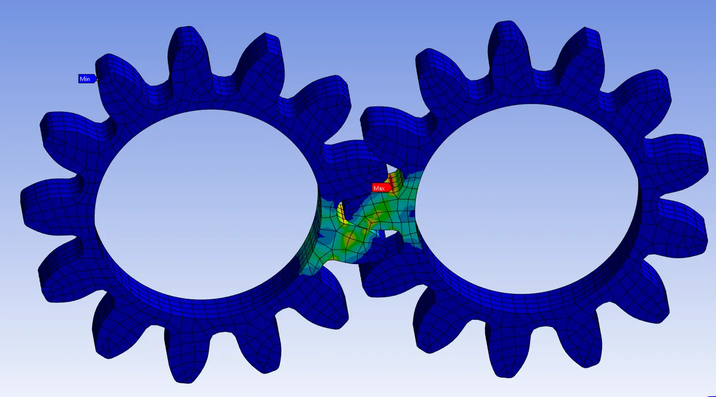
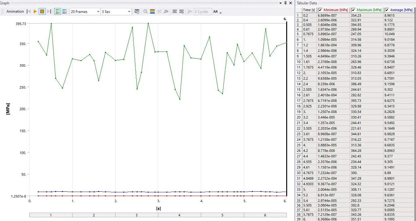
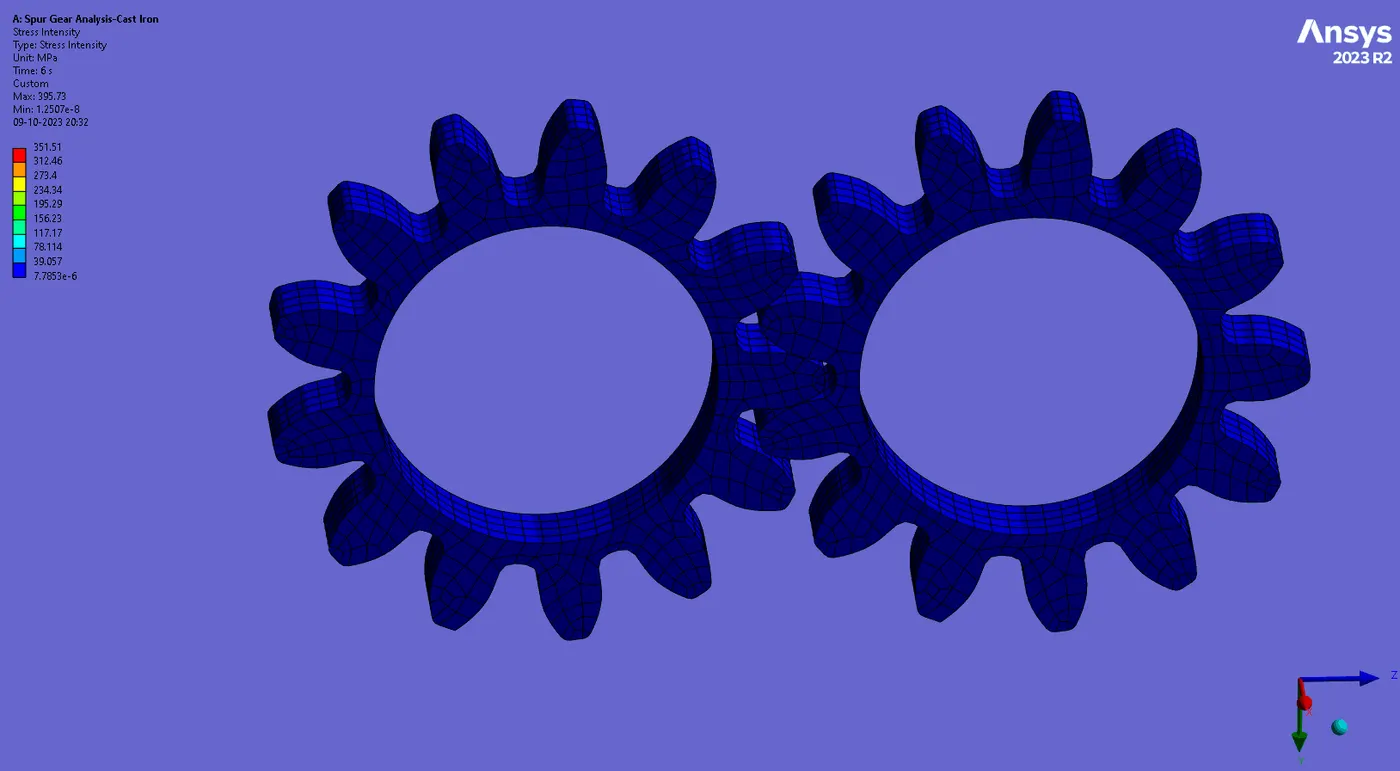
The maximum stress intensity was observed same at the root of the tooth where interference between 2 mating gears will be maximum @ 351 MPa
CONTACT STATUS:
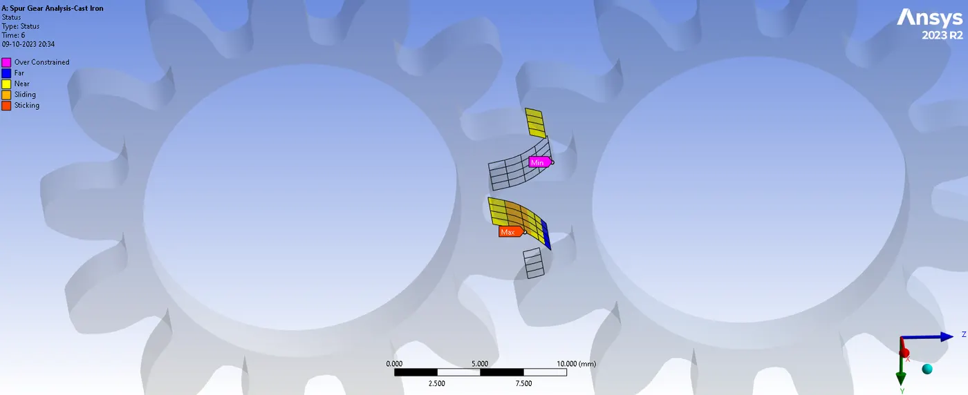
The contact between 2 gears looks to be good because as shown below the red region indicates sticking the chrome yellow indicates its sliding and in the actual scenario it slides and then moves away after every periodic interval of mate.
The contact status has been displayed below indicating the real-time scenario of the two gears
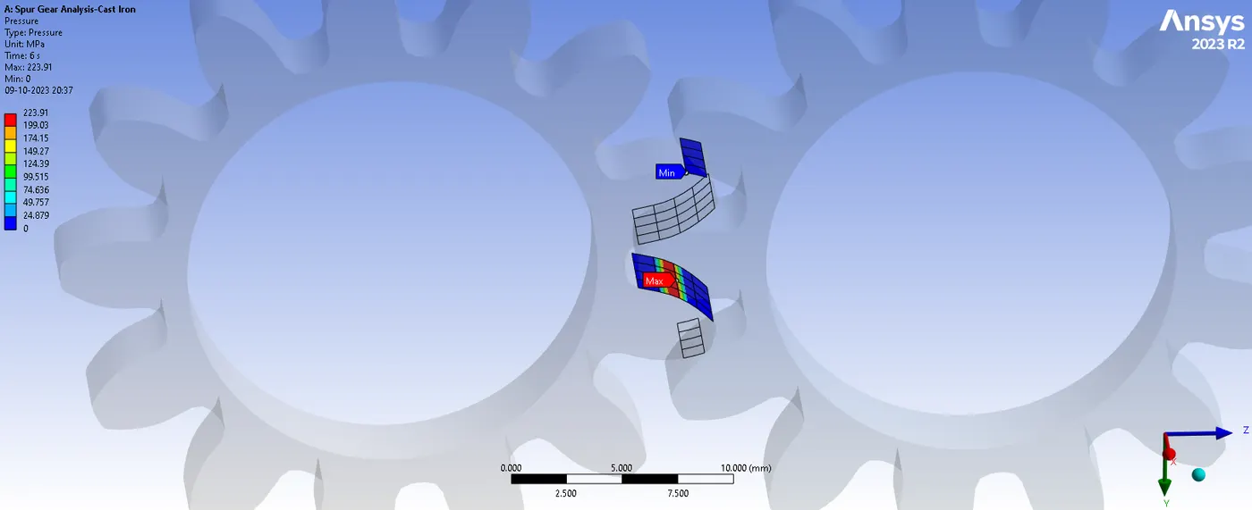
Contact Pressure of a Maximum 224 Mpa has been observed at the point of contact between 2 mating gear tooth shown below:
RESULTS CASE 2: (CAST STEEL)
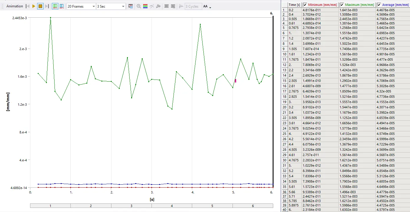
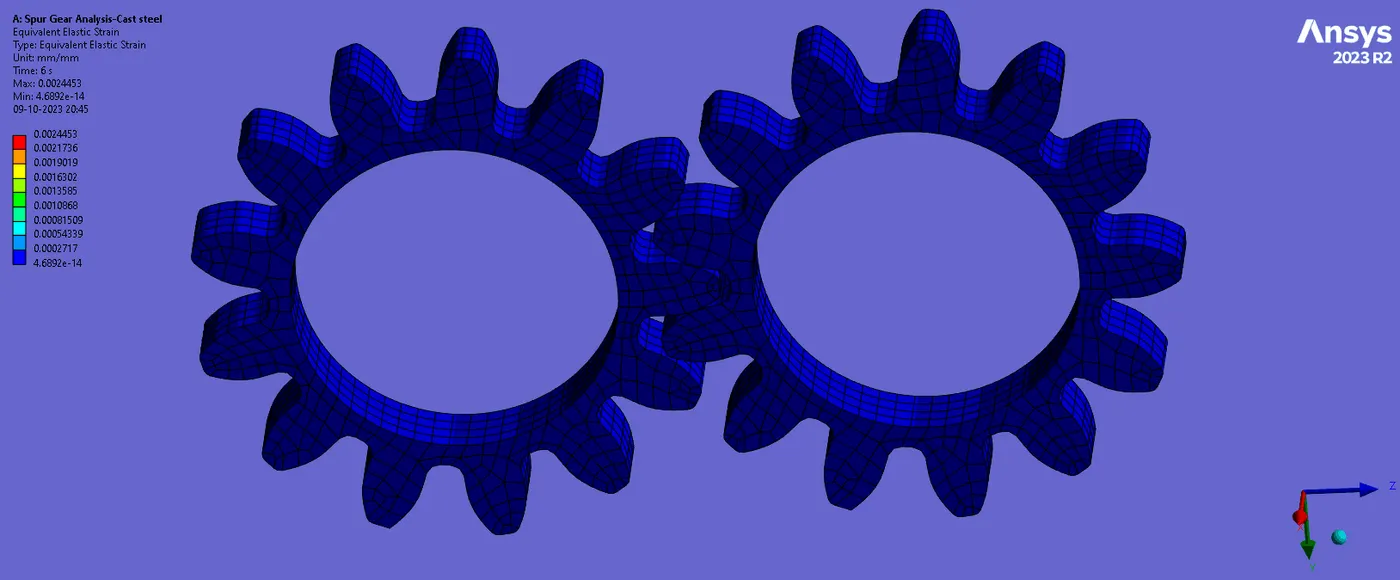
Equivalent Strain
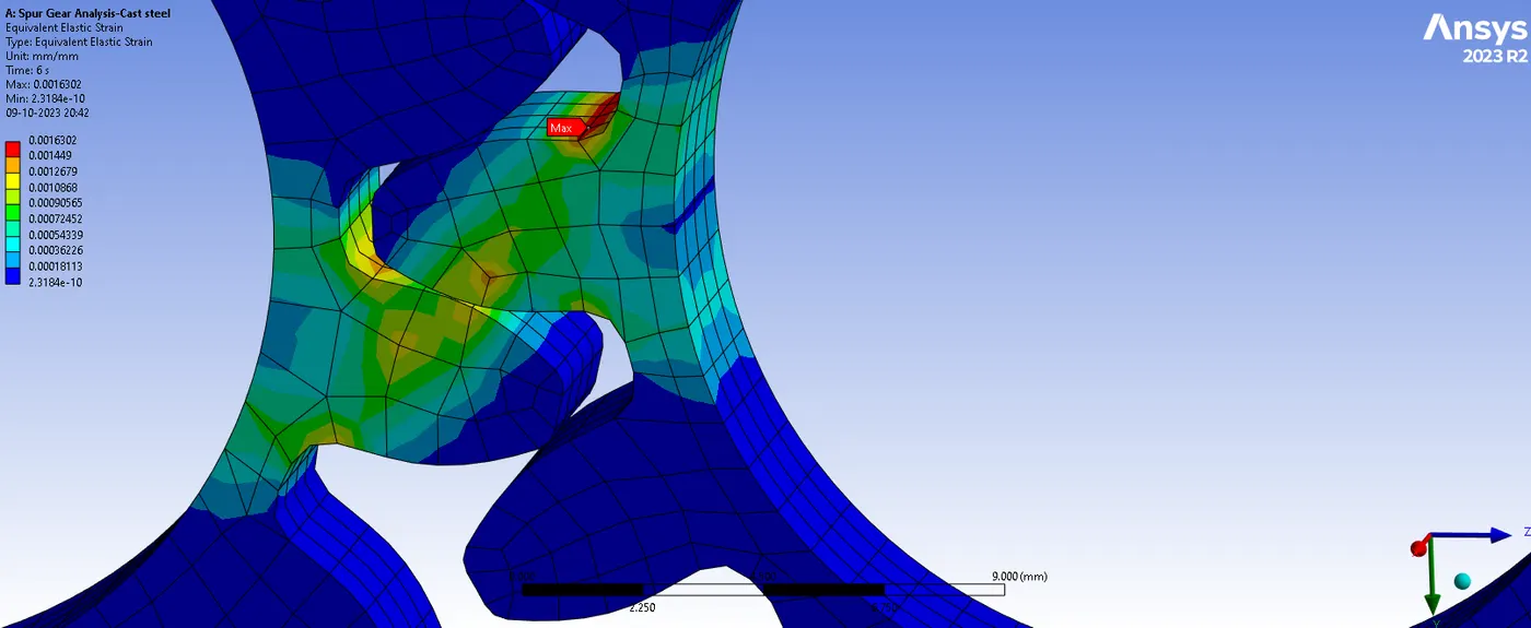
The maximum strain observed in the tooth of the gears where interference is there as shown above
Equivalent Stress:
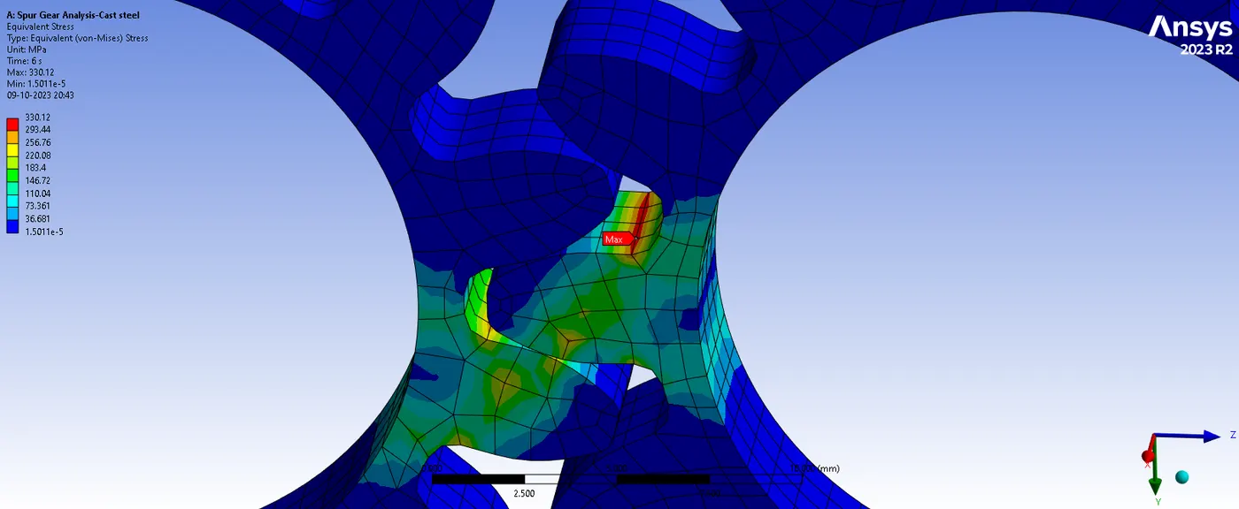
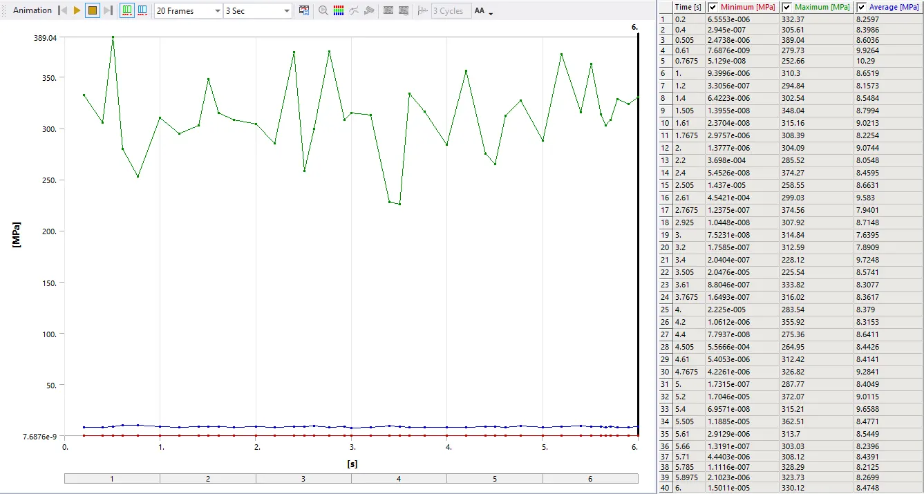
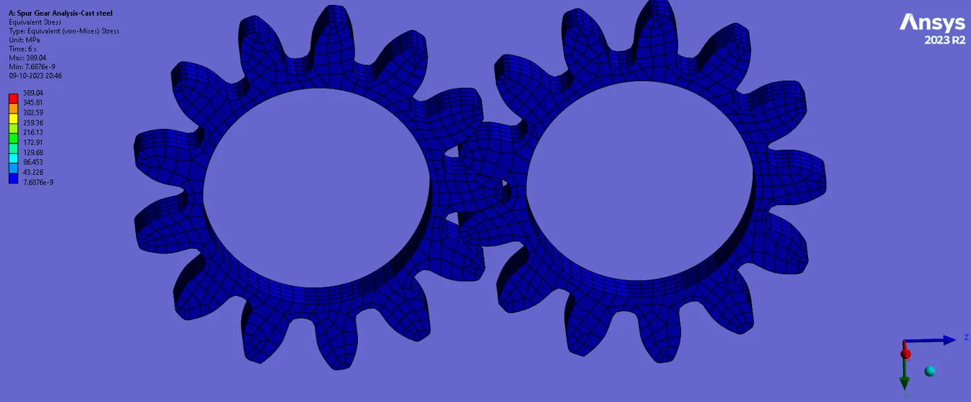
The maximum stress was observed to be the same at the root of the tooth where interference between 2 mating gears will be maximum @ 389 MPa
Total Deformation
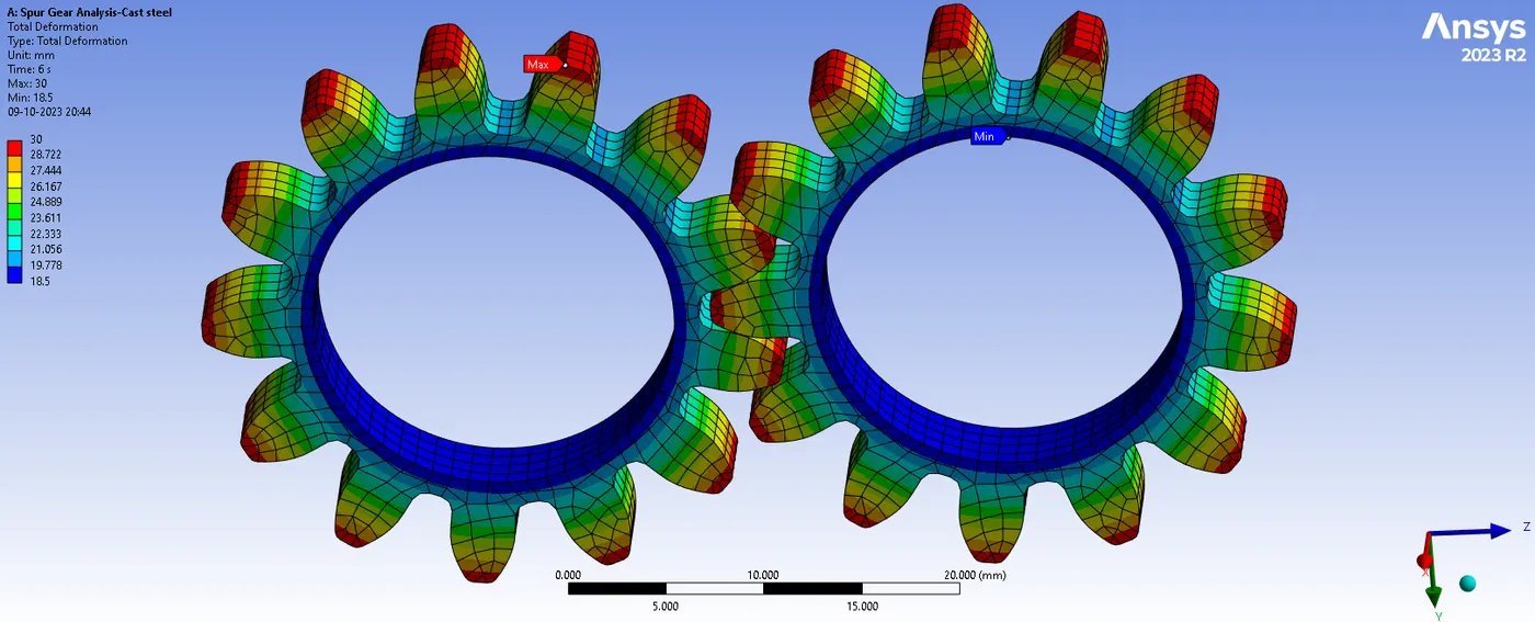
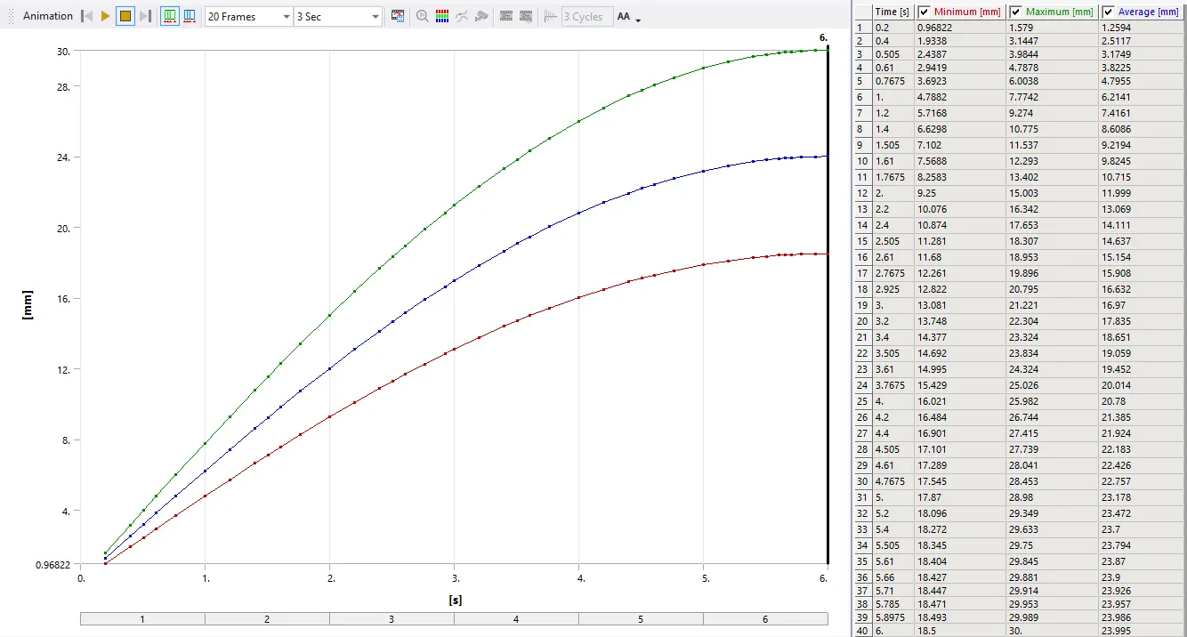
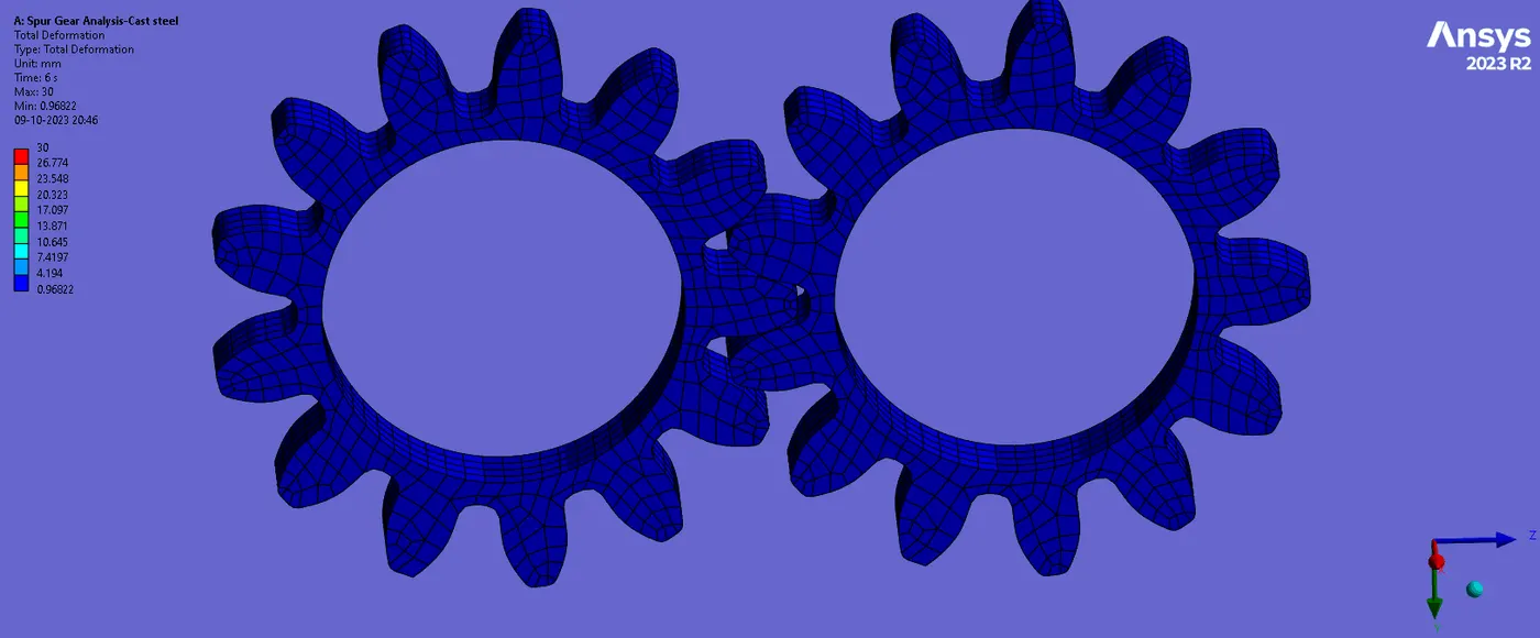 The maximum Deformation was observed same at the end of the tooth where interference between 2 mating gears will not be maximum @ 30 mm
Stress Intensity
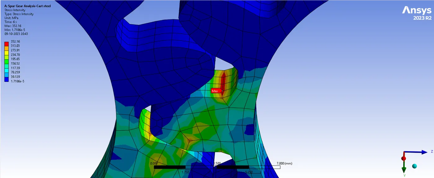

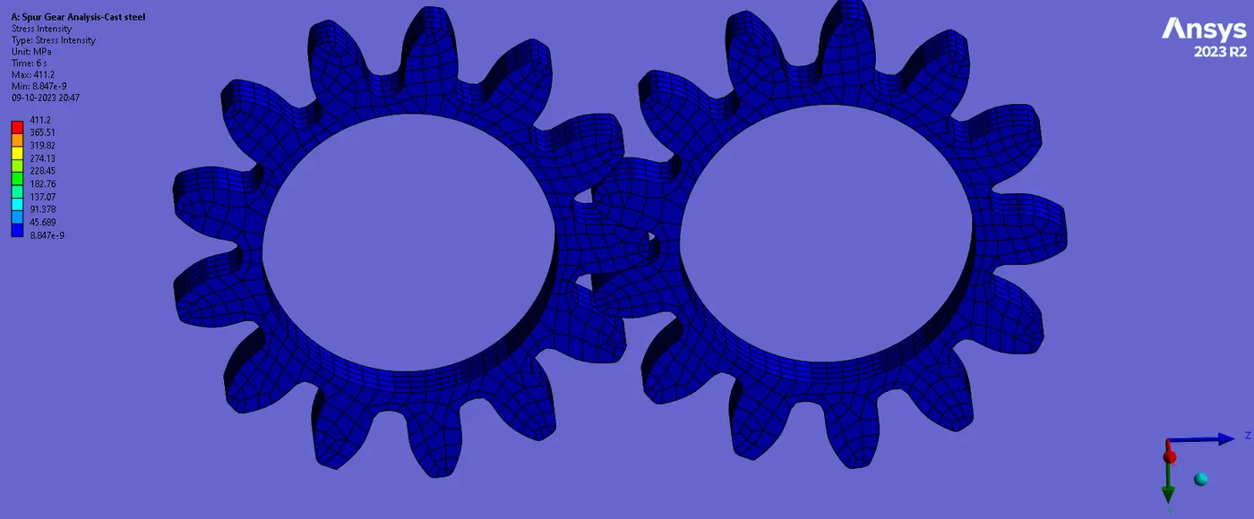
The maximum stress intensity was observed same at the root of the tooth where interference between 2 mating gears will be maximum @ 411 MPa
CONTACT STATUS:
The contact status remains to be similar for all the other 2 conditions as executed for CAST IRON shown earlier in the respective section
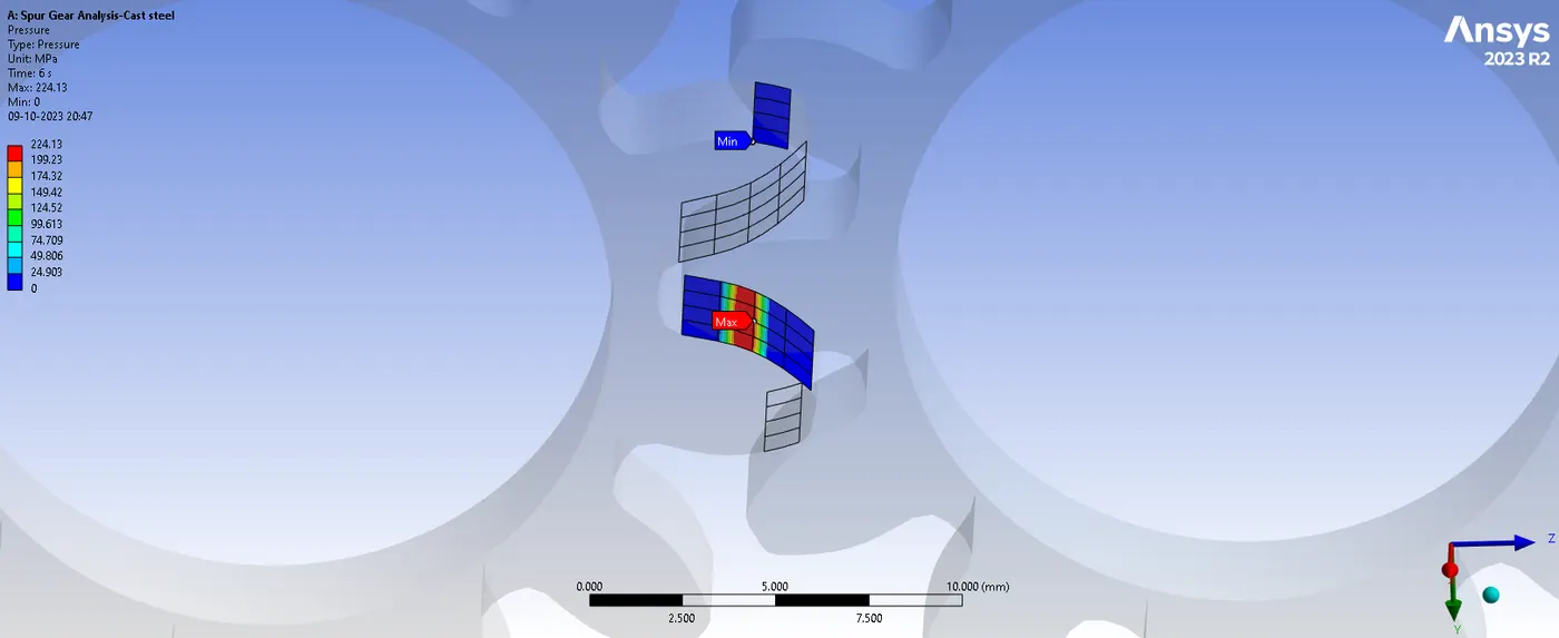
Contact Pressure of a Maximum 224 Mpa has been observed at the point of contact between 2 mating gear tooth shown below:
RESULTS CASE 3: (CAST BRONZE)
Equivalent Strain
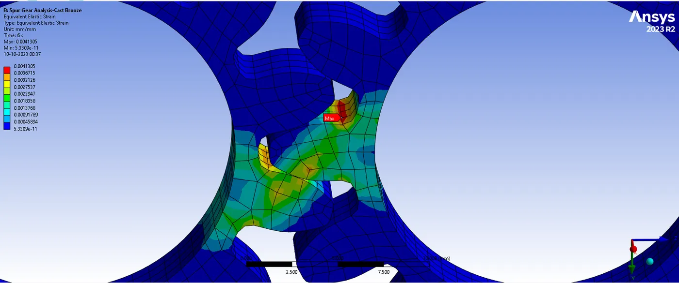
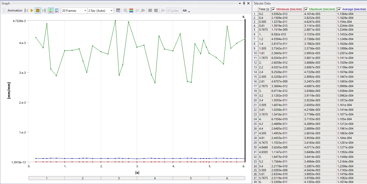
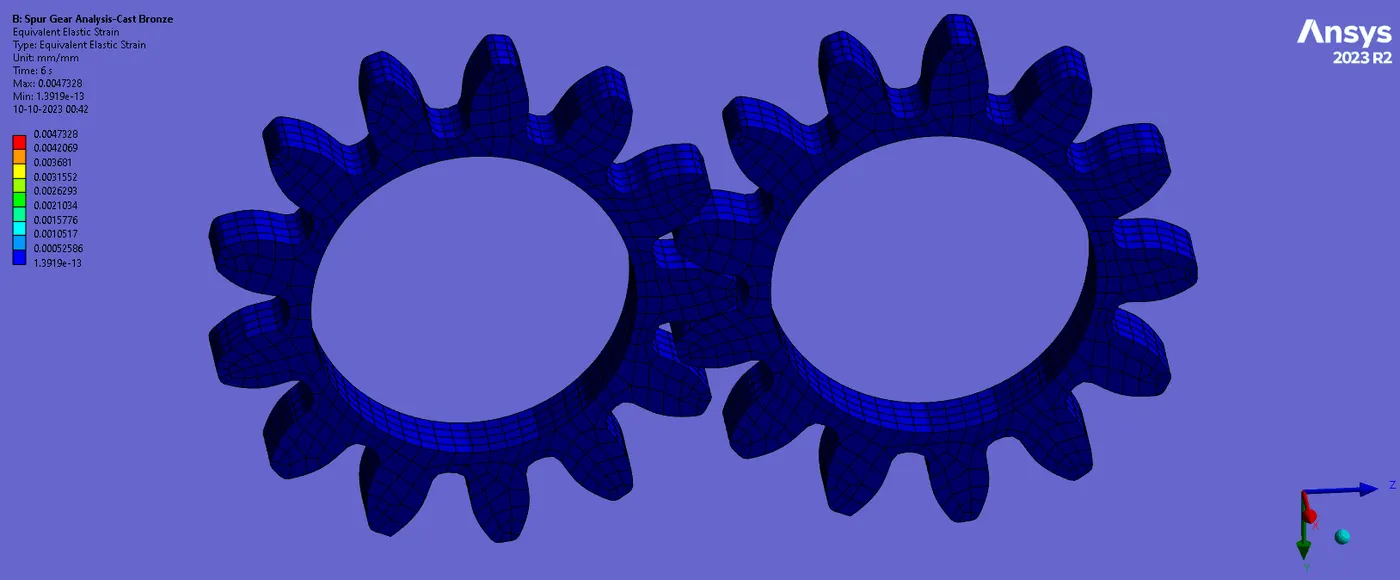
The maximum strain observed in the tooth of the gears where interference is there as shown above
Equivalent Stress:
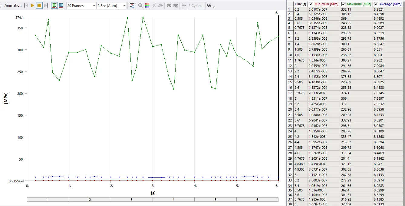
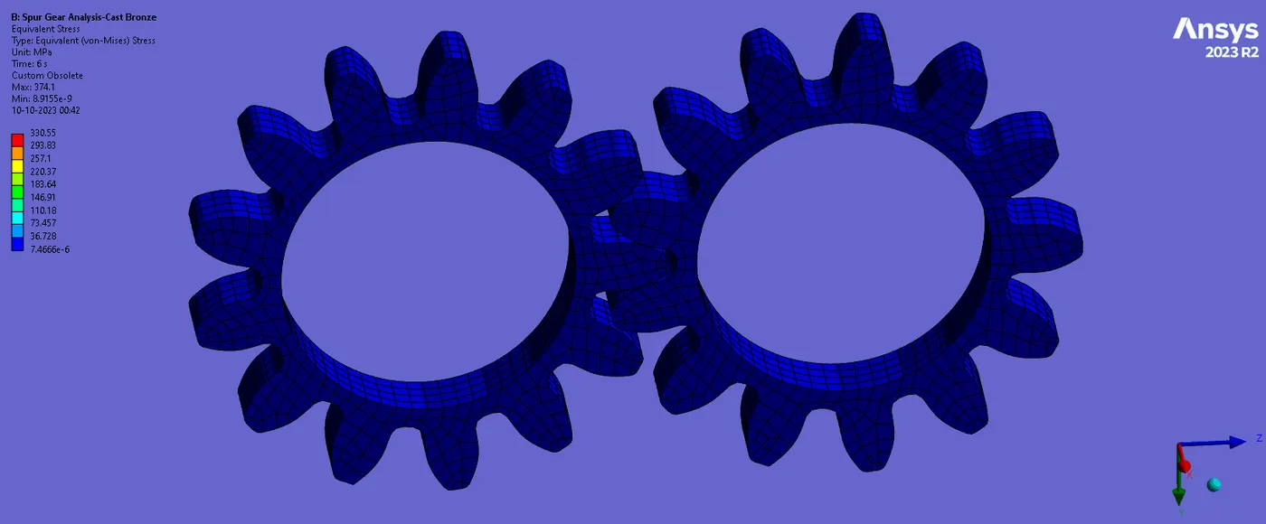
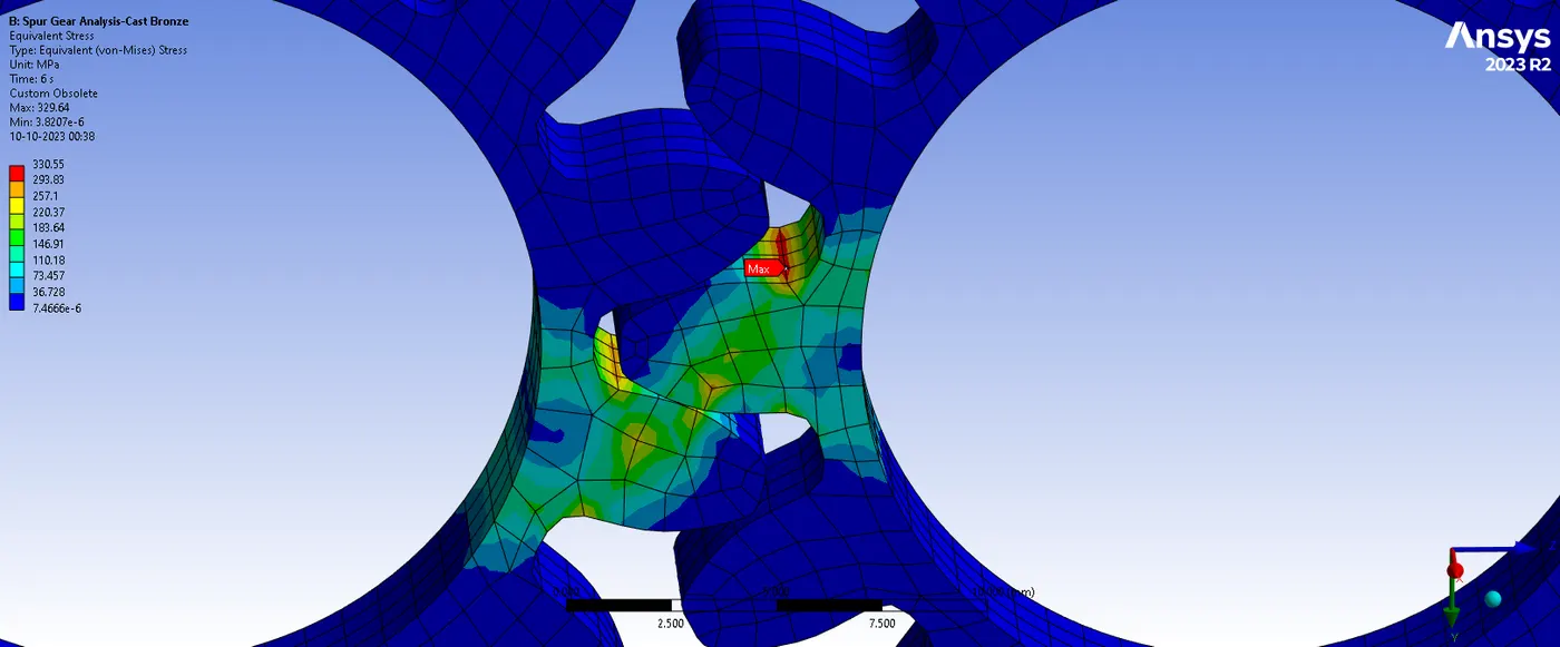
The maximum stress was observed to be the same at the root of the tooth where interference between 2 mating gears will be maximum @ 330 MPa
Total Deformation
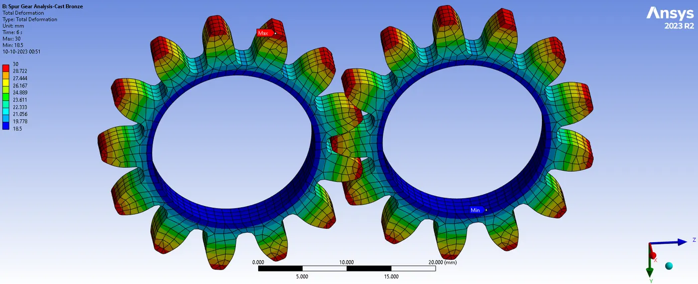
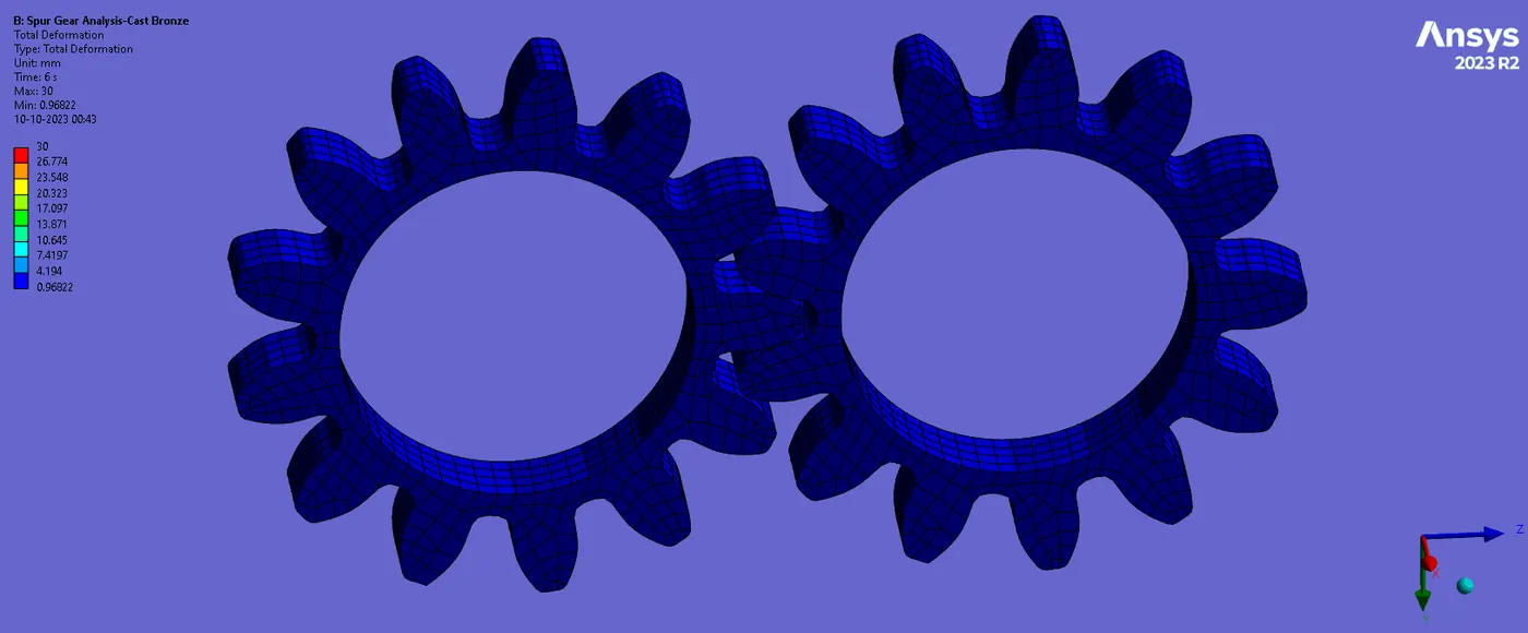
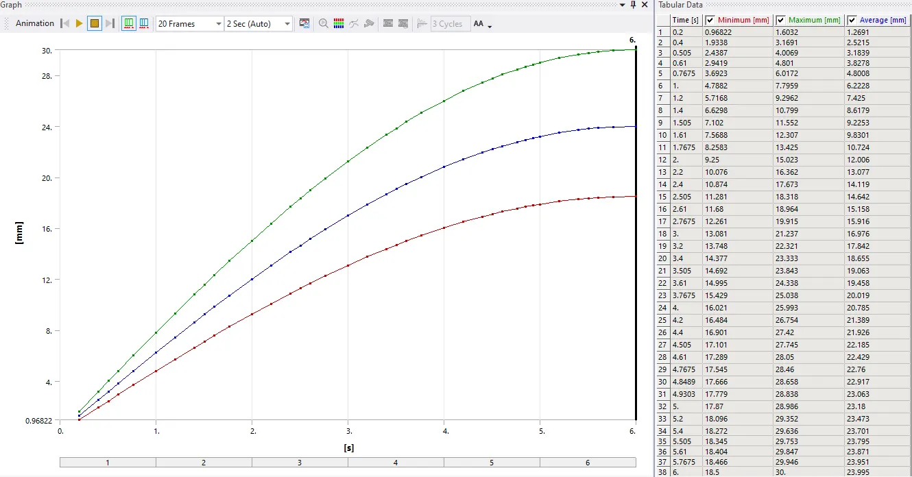
The maximum Deformation was observed same at the end of the tooth where interference between 2 mating gears will not be maximum @ 30 mm
Stress Intensity
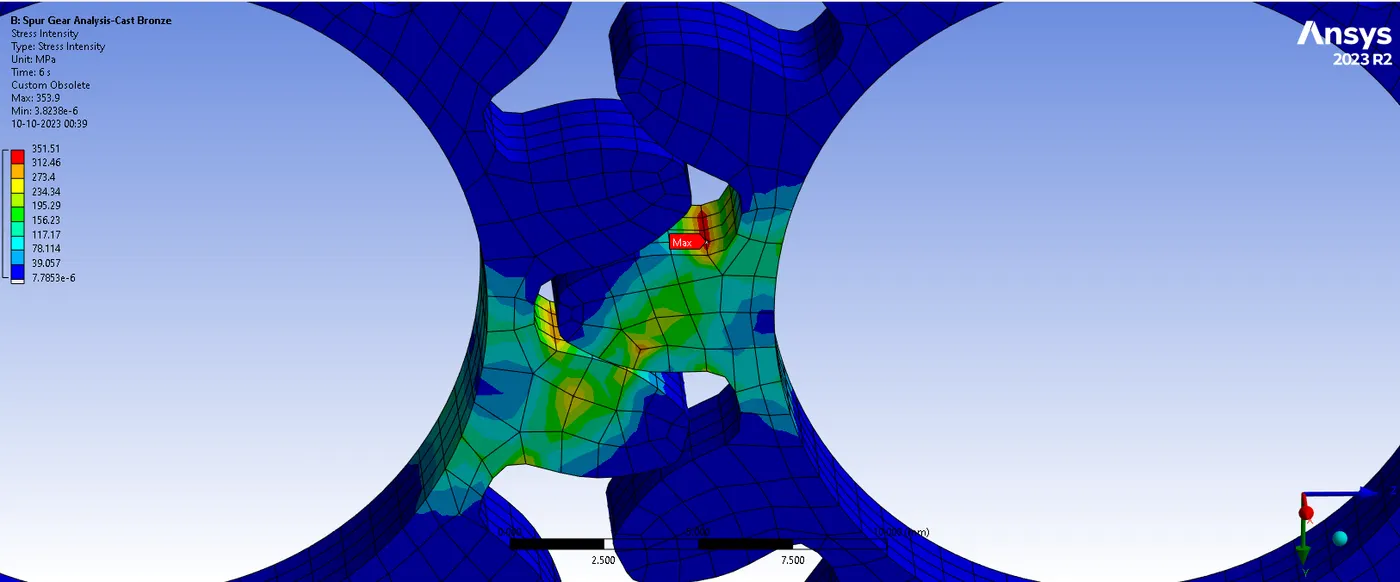
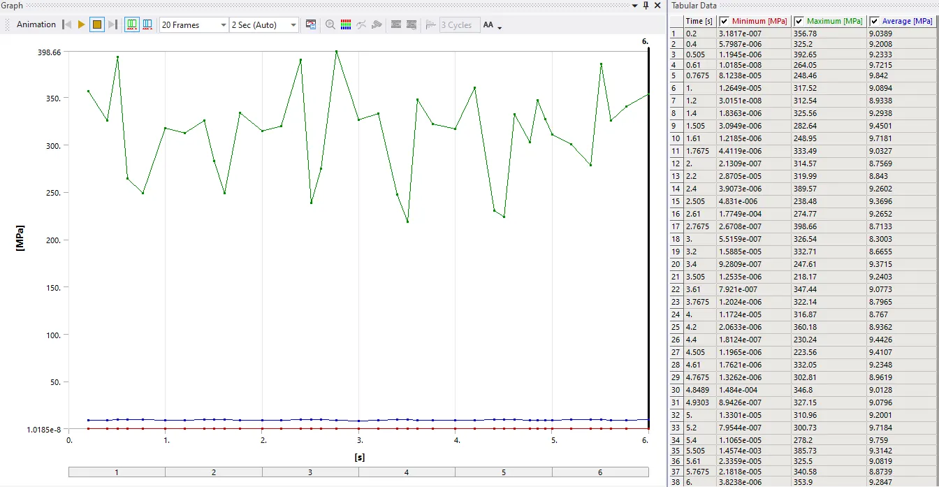
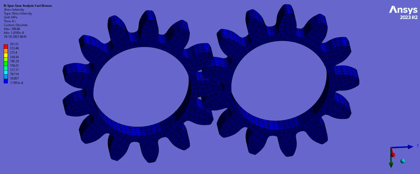
The maximum stress intensity was observed same at the root of the tooth where interference between 2 mating gears will be maximum @ 352 MPa
CONTACT STATUS:
The contact status remains similar for all the other 2 conditions as executed for CAST IRON shown earlier in the respective section
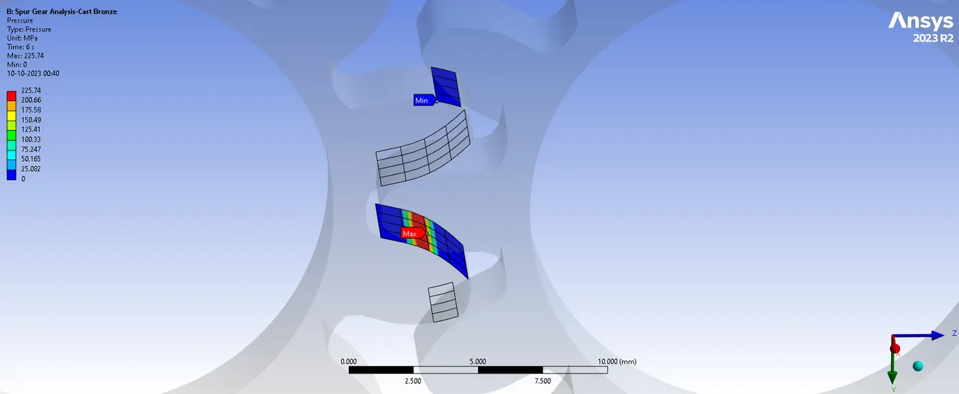
Contact Pressure of a Maximum 225 Mpa has been observed at the point of contact between 2 mating gear teeth shown below:
STRESS INTENSITY FACTOR
The stress intensity factor is used in fracture mechanics to predict the stress state ("stress intensity") near the tip of a crack or notch caused by a remote load or residual stresses. It is a theoretical construct usually applied to a homogeneous, linear elastic material that is useful for providing a failure criterion for brittle materials and is a critical technique in the discipline of damage tolerance. The concept can also be applied to materials that exhibit small-scale yielding at a crack tip. The magnitude of stress intensity depends on specimen geometry, the size and location of the crack or notch, and the magnitude and distribution of loads on the material. It can be written as:
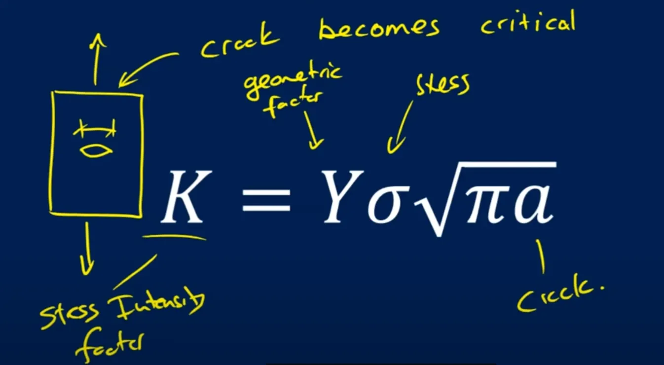
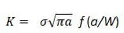
Where, f (a/W) is a specimen geometry dependent function of the crack length a, and the specimen width W, and applied stress.
Linear elastic theory predicts that the stress distribution near the crack tip, in polar coordinates
with origin at the crack tip, has the form as:
Where is the stress intensity factor (with units of stress length1/2) and is a dimensionless quantity that varies with the load and geometry Theoretically, as goes to 0, the stress goes to results in a stress singularity. Practically, however, this relation breaks down very close to the tip (small) because plasticity typically occurs at stresses exceeding the material's yield strength and the linear elastic solution is no longer applicable. Nonetheless, if the crack-tip plastic zone is small in comparison to the crack length, the asymptotic stress distribution near the crack tip is still applicable.
Stress Intensity Factors for Various Modes:
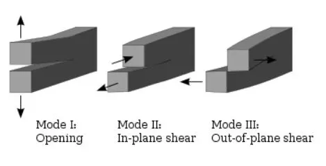
o Mode I is an opening (tensile) mode, Where the crack surfaces move directly apart.
o Mode II is a sliding (in-plane shear) mode where the crack surfaces slide over one another in a direction perpendicular to the leading edge of the crack.
o Mode III is a tearing (anti-plane shear) mode where the crack surfaces move relative to one another and parallel to the leading edge of the crack. Mode I is the most common load type encountered in engineering design.
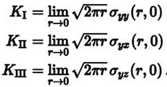
Different subscripts are used to designate the stress intensity factor for the three different modes. The stress intensity factor for mode I Is designated KI and applied to the crack opening mode. The mode KII stress intensity factor, applies to the crack sliding mode and
The mode III stress intensity factor, KIII, applies to the tearing mode. These factors are formally defined as:
CONCLUSION AND DISCUSSION:
- Based upon the type of application we need to decide the material suitable for usage as Cast Iron material will give good hardness as its usage is in lathe gear type applications where excessive load bearing is not applied
- Due to this usage, it can have a long life and it is much more reliable for box-type transmission applications.
- If CAST STEEL which has obviously better properties in material management as the carbide percentage is higher in this which is in a nodular packed structure makes its usage in heavy machinery applications as well as in heavy transmissions, even though its hardness is less compared to CAST IRON which can be further increased via heat treatment process and Case Hardening procedure.
- Whereas CAST BRONZE usage is in applications where precision is a major concern and it's an expensive material, it is used to wormgear boxes it is not suitable for heavy operations because it will easily damage while giving load when compared to the other two discussed earlier in this section.
|
Sr .No |
Deformation (mm) |
Von-Mises Stress (Mpa) |
Equivalent Strain (mm) |
Stress-Intensity (Mpa) |
|
|
CAST IRON |
30 |
331 |
0.003 |
352 |
|
|
CAST STEEL |
30 |
389 |
0.001 |
411 |
|
|
CAST BRONZE |
30 |
331 |
0.005 |
351.5 |
|
Based upon the analysis we will go for CAST STEEL material due to its good load-carrying capacity and mostly it is used in the heavy gear box transmission system.
The stresses and deformation plot of bronze and CI are almost same where as CI and bronze both failed as its FOS is less than 1 (Factor of Safety) with respective to Ultimate tensile strength
As my theory says FOS should be =1 or more than that,
CAST STEEL though stress intensity is little high but it matches all the criteria my FOS is more than 1 as its UTS is 505Mpa
The stress intensity factor is used to know whether the material will fracture or not, if the stress intensity factor exceeds the fracture toughness value, then the material will fracture.
The manufacturing point its economical and vividly used and undergoing heat treatment its hardenability will be achievable, thus there will be a reduction in Stress intensity.