Week 2 : Basic Calibration of Single cylinder SI-Engine
Aim:
* The Main objective of this project is to set up and run the model for a single cylinder four stroke SI Engine at 1800 rpm
* To run the same model at 3600 rpm and increases the power - output by 10%
Introduction:
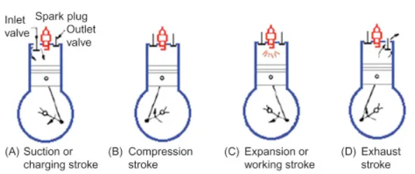
The Spark ignition (SI) engine is an internal combustion engine , where the air fuel mixture is ignited by a spark from the spark plug.
The four stroke SI engine is an otto cycle engine and consists of four stroke called Suction, Compression, Power, Exhaust . These comprise an intake where fuel-air is drawn into the engine. And then air fuel mixture is get compressed. And in the Power stroke the fuel is ignited and expands. In the exhaust the combustion particle are expelled from the engine
During each stroke the crank shaft completes of 180 degrees of rotation and hence the entire four strokes are completed in 720 degrees. Therefore for every cycle the crank shaft completes two revolution where there is only one power stroke.
Air -flow rate:
It is the amount of air that is entering the engine and it is important because it decides how the fuel combustion takes place . A low air flow produces incomplete combustion leading to CO emission where a higher fuel ratio leads to NOx Emissions . Therefore the air flow close to stoichiometry is desired
Break mean Effective Pressure:
It is the ratio of gross work done per cycle to the volume displaced per cycle . It provides a valuable measure of the engine performance which is independent of the engine displacement.
Break Specific fuel Consumption :
It is the amount of fuel Consumed per unit Power Produced in a cycle. Low values of BFSC are desirable.
In Cylinder Pressure:
It is the maximum Pressure that is developed inside in the engine during a single cycle. The cylinder pressure provides a measure of work that can be extracted from the engine.
Model Setup:
The model is setup from scratch by following the in -built tutorial on a single cylinder SI Engine. The figure shows the structure of the model .
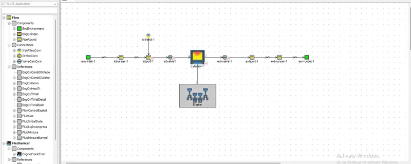
This model uses the WoschniGT model for heat transfer . This model closely emulates the classical Woschni correlation without swirl. A wiebe function is used here to impose the combustion burn rate. In this model , the fuel is injected into the inlet port and the amount of fuel injected depends on the specified Air -fuel ratio and the air flow rate in the intrunner . The in built indolene -combust model was used for the fuel. The timing of the fuel injection is controlled by the cylinder. The specification of the engine used in the model is summarized in the below table.
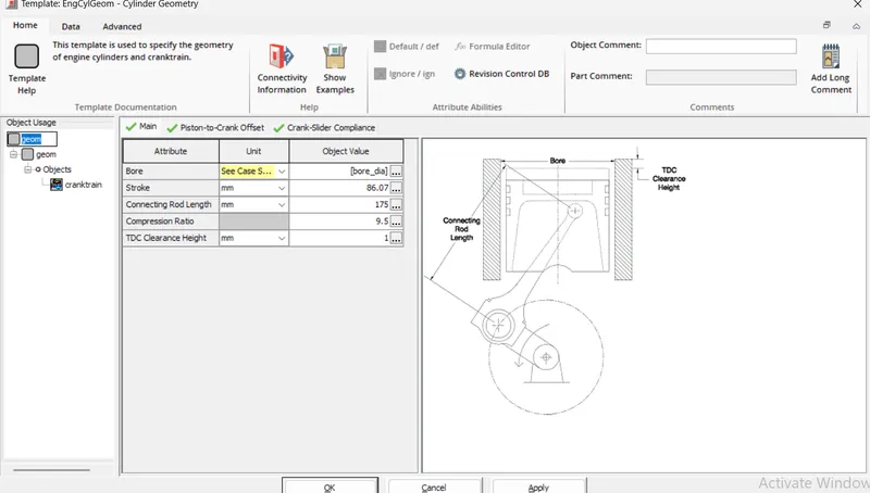
Geometrical Parameters:
Number of Cylinder 1
Bore 86 mm
stroke 86.07 mm
Connecting rod length 175 mm
Compression ratio 9.5
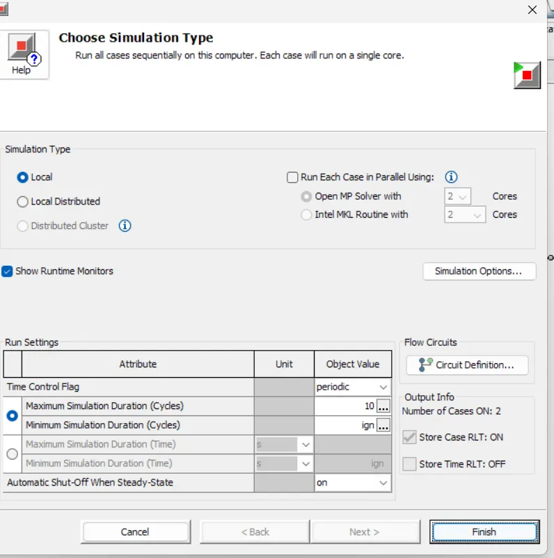
No of Cycles:10
Results:
The model was run with an rpm of 1800 and 3600 for 10 cycles and the important operating parameters were observed and mentioned below.
|
Parameters |
RPM 1800 |
RPM 3600 |
|
Air Flow rate (kg/h) |
24.6 |
58.6 |
|
BMEP (bar) |
9.5 |
11.1 |
|
BSFC (g/kw-h) |
239.2 |
241.8 |
|
Max cylinder Pressure (bar) |
48.89 |
58.9 |
|
Brake power (KW) |
7.1 |
16.7 |
|
Brake Torque (N-m) |
37.7 |
44.3 |
|
Brake efficiency (%) |
34.4 |
34.1 |
From the above table , it can be observed that the engine Produces high power at a higher rpm.
Case2:
Increase the power by 10% at 3600 rpm.
At 3600 rpm , the engine with the current Configuration and operating Conditions Produces KW. A 10% increase is in result of KW.
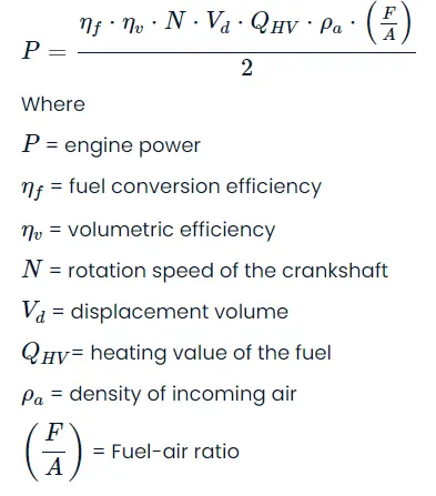
For a Four stroke engine, the relationship between the power and the other operating parameters is given by the following equation
From the above equation , it can be observed that the power of an engine can be increased by
- Increasing the volumetric efficiency
- Increasing the fuel conversion Efficiency
- Increasing the rpm
- Increasing the displacement volume
- Using fuel with higher heating value.
- Increasing the density of incoming air
- Increasing the fuel air ratio or decreasing the air fuel ratio increase the richness of fuel burning
In this case we going to analyze the effect of displacement volume, density of incoming air and the air fuel ratio on the engine break power.
Case 1:
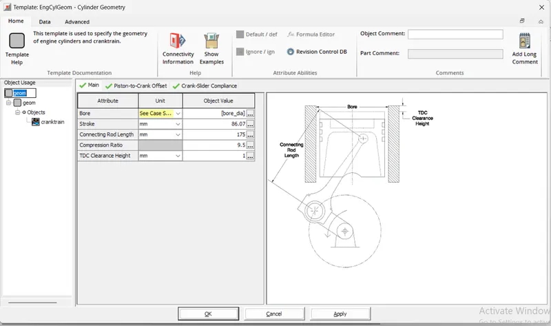
The displacement volume can be increased by bore, stroke or by both.
Case 1.1:
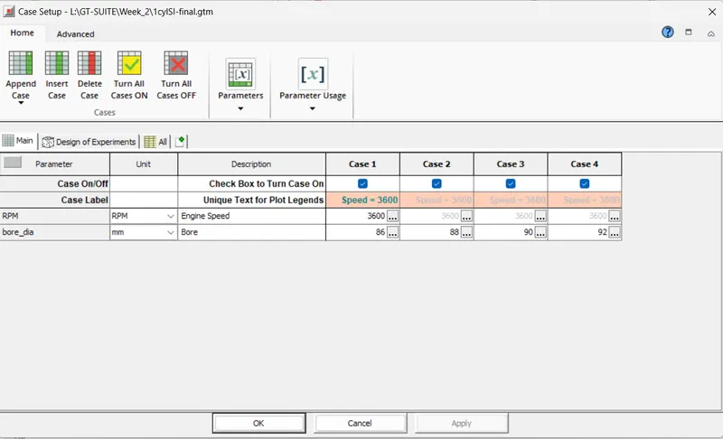
In this case the model was run with four different values 86 mm, 88 mm, 90mm, 92 mm
Here the stroke value was maintained constant at 86.07 mm
The case setup are shown in below figure:
Results:
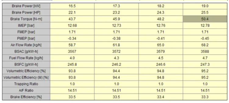
It can be observed that the brake power increases with increasing the bore , It can also be observed that the volumetric efficiency also increased with increasing the bore value. The bore value of 90 mm gives the 10% of increase in power.
Case 1.2:
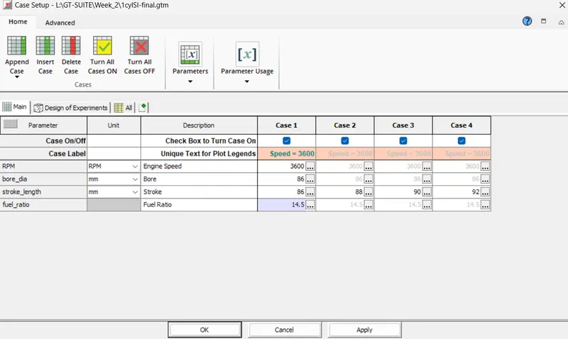
In the case , the model was run with four different stroke values 86 mm, 88 mm, 90mm, 92 mm
Here the bore value was maintained constant at 86mm
The case setup are shown in below figure:
Results:
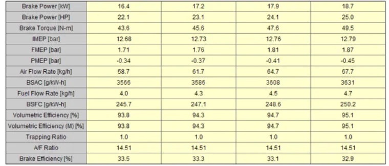
The same results are observed here, the brake power increases with increase in the stroke length
To Get 10% increase in power the stroke need to to be increased to 98 mm.
Case2:
Assuming the ideal gas , the density is given by:
Density=P/R*T
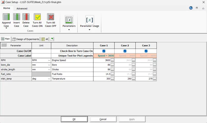
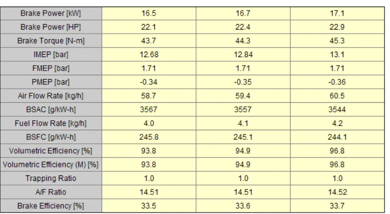
The density of air is inversely proportional to its temp,Therefore the model was run with three different temp 300K, 295k, 290k. while the other parameters remained constant . In practical cases , the air density will be increased with a turbo charger or a super charger.
The case setup are shown below:
It can be observed that by decreasing the inlet temp, the air flow rate increased and there by the brake power also increased However Maintaining a low temp will not be possible at every operating conditions , Therefore in practice the air density is usually increased using a turbo charger or a super charger.
Case 3:
In this case the air fuel ratio was changed to 8, 10, 12 ,14 . and its effects of the engine power is studied
The case setup are shown below:
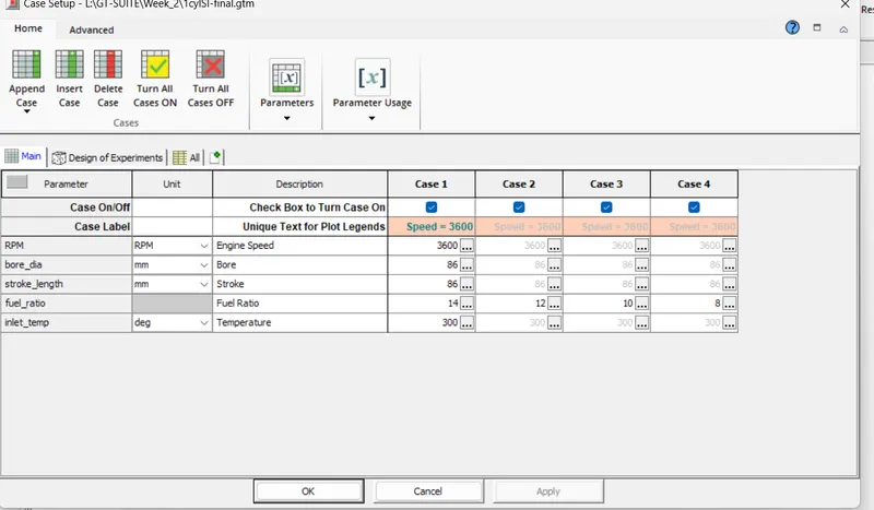
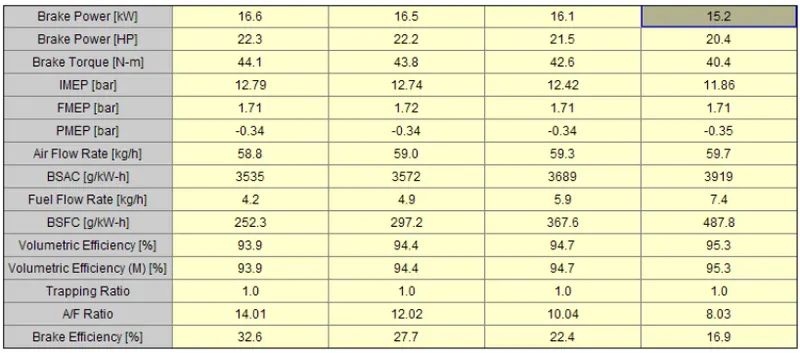
It can be observed from the above table , the richening the fuel actually leads to decrease in the brake power . This is because at low concentration of air, and all fuel are not converted into energy and some fuels are remains un-burnt . which leads to increase the CO Emission.
The same effect can be observed by increasing the fuel inject rate while keeping the air fuel ratio constant.
Conclusion:
In this project the 1D Model of a single cylinder four stroke SI Engine was successfully developed in the GT-Suite.The model was then used to study the effect of different parameters in increasing the brake power of the engine at 3600 rpm.