Week 12 - Validation studies of Symmetry BC vs Wedge BC in OpenFOAM vs Analytical H.P equation
Validation studies of Symmetry BC vs Wedge BC in OpenFOAM vs Analytical H.P equation
Objective :
1. Simulate an axi-symmetric flow by applying the wedge boundary condition at wedge angles of `10^circ`, `25^circ` & `45^circ`
2. Validate Hydro-dynamic length with the numerical result
3. Validate the fully developed flow velocity profile with its analytical profile
4. Validate maximum velocity and pressured drop for fully developed flow
5. Post-process Shear stress and validate wall shear stress for fully developed flow
Description :
Hagen Poiseuille equation
It is a physical law that gives the pressure drop in an incompressible and Newtonian fluid in laminar flow flowing through a long cylindrical pipe of constant cross section.
Boundary Layer Theory :
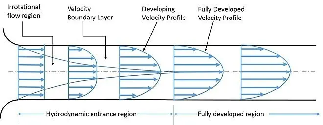
When fluids flow over surfaces, the molecules near the surface are brought to rest due to the viscosity of the fluid. The adjacent layers are also slow down, but to a lower and lower extent. This slowing down is found limited to a thin layer near the surface. The fluid beyond this layer is not affected by the presence of the surface. The fluid layer near the surface in which there is a general slowing down is defined as boundary layer. The velocity of flow in this layer increases from zero at the surface to free stream velocity at the edge of the boundary layer.
When a real fluid flow past a solid body or a solid wall, the fluid particles adhere to the boundary and condition of no slip occurs. This means that the velocity of fluid close to the boundary will be same as that of the boundary. If the boundary is stationary, the velocity of fluid at the boundary will be zero. The theory dealing with boundary layer flows is called boundary layer theory.
The fluid, originally having velocity `U_infty` in the direction of plate, is retarded in the neighbourhood of the surface, and the boundary layer begins at the leading edge of the plate. As more and more of the fluid is slowed down, the thickness of the layer increases. The fluid in contact with the plate surface has zero velocity, ‘no slip’ and a velocity gradient exists between the fluid in the free stream and the plate surface.
The flow in the first part of the boundary layer (close to the leading edge of the plate) is entirely laminar. With increasing thickness, however, the laminar layer becomesunstable, and the motion within it becomes disturbed. The irregularities of the flow develop into turbulence, and the thickness of the layer increases more rapidly.
The changes from laminar to turbulent flow take place over a short length known as the transition region.
Terminologies describing the fully developed flow
1. Hydrodynamic Entrance region : The hydrodynamic entrance region of a microchannel is that region where the velocity boundary layer is developing from zero thickness at the entrance up to cover the whole cross-section far downstream
2. Fully developed Region : If a fluid enters the channel with uniform velocity, a hydrodynamic boundary layer begins to develop, forming an entrance region. It becomes fully developed at certain distance from the entrance, forming a fully–developed region.
Assumptions for Hagen Poiseuille :
Entry length for laminar flow (`L_e`) = `0.06*R_e*D`
Diameter (D) = 0.01 m
At `25^(circ)C`
Water
1. Density `(rho)` = 997`(kg)/m^3`
2. Kinematic Viscosity of water `25^(circ)C` `(nu)` = `8.917xx10^-7 m^2/s`
3. Dynamic Viscosity of water `25^(circ)C` `(mu)` = `(rho*nu)` = `8.89xx10^-4`
4. Reynolds Number `(R_e) = 2100`
`R_e = [rho*V_(avg)*(D/mu)]`
5. Average Velocity `(V_(avg))` = `[frac{mu*R_e}{rho*D}]`
= 0.1872 m/s
6. `V_(max)/V_(avg)` = 2
`V_(max)` = 0.3745 m/s
7. Pressure Drop `(Deltap)`
`Delta p = 8*mu*V_(avg)*(L/r^2)`
8. `L_e = 0.06*R_d*D`
= 0.06*2100*0.02
`L_e` = 2.52 m
9. Total length of Pipe (L) = `L_e +0.3`
= 1.26+0.3
L = 1.56 m
10. Kinetic Pressure
p = `(Deltap)/(rho)`
= `83.077/997`
= 0.0883 `m^2/s^2`
Matlab code for Symmetric Boundary Condition (For 10 degree wedge angle):
close all
clear all
clc

% Input data

Re = 2100; % Reynold's Number'
D = 0.01; % Dia of pipe in m
rho = 997; %Density of water
nu = 8.917e-7; % Kinematic viscosity of water

% CALCULATIONS
mu = rho*nu; %Dynamic viscosity
V_avg = mu*Re/(rho*D);
V_max = 2*V_avg;

r = D/2; % Radius of pipe in m

L_e = 0.06*D*Re ; % Hydrodynamic length at entrance
L = L_e + 0.3; % Total length of pipe

% Hagen Poisuelle Equation
delta_p = 8*mu*V_avg*(L/r^2);
kinematic_p = delta_p/rho; % Kinematic pressure


% Wedge angle
theta = input("Enter the value of the wedge angle:"); %Wedge angle should be less than 5 degrees


% Calculating shear stress
R = linspace(0,D/2,1000);

for i = 1:length(R)
    tau(i) = 2*mu*V_max*(abs(R(i)))/r^2 ;
end

% Plot
plot(R,tau);
xlabel('Radius in m');
ylabel('Shear stress');
title('Variation of shear stress along radius cylinder');
grid on
hold on


% Defining the vertices of the block
v0 = [0 0 0];
v1 = [0 r*cosd(theta/2) -r*sind(theta/2)];
v2 = [0 r*cosd(theta/2) r*sind(theta/2)];
v3 = [L 0 0];
v4 = [L r*cosd(theta/2) -r*sind(theta/2)];
v5 = [L r*cosd(theta/2) r*sind(theta/2)];

% Header file (openFoam)

h1 = '/*--------------------------------*- C++ -*----------------------------------*\';
h2 = '|  =========                 |                                                |';
h3 = '|  \\      /  F ield         | OpenFOAM: The Open Source CFD Toolbox          |';
h4 = '|   \\    /    O peration     | Website:  https://openfoam.org                |';
h5 = '|    \\  /    A nd           | Version:  9                                    |';
h6 = '|     \\/     M anipulation  |                                                |';
h7 = '/*---------------------------------------------------------------------------*/|';
h8 = 'FoamFile';
h9 = '{';
h10 =     'version     2.0;';
h11 =     'format      ascii;';
h12 =     'class       dictionary;';
h13 =     'object      blockMeshDict;';
h14 = '}';
h15 = '// * * * * * * * * * * * * * * * * * * * * * * * * * * * * * * * * * * * * * //';


f1 = fopen('blockMeshDictadeg.txt','w');
fprintf(f1,'%s \n', h1);
fprintf(f1,'%s \n', h2);
fprintf(f1,'%s \n', h3);
fprintf(f1,'%s \n', h4);
fprintf(f1,'%s \n', h5);
fprintf(f1,'%s \n', h6);
fprintf(f1,'%s \n', h7);
fprintf(f1,'\n');
fprintf(f1,'%s \n', h8);
fprintf(f1,'%s \n', h9);
fprintf(f1,'%s \n', h10);
fprintf(f1,'%s \n', h11);
fprintf(f1,'%s \n', h12);
fprintf(f1,'%s \n', h13);
fprintf(f1,'%s \n', h14);
fprintf(f1,'%s \n', h15);
fprintf(f1,'\n');


fprintf(f1,'%2s\n\n','convertToMeters 1;');
fprintf(f1,'\n');


% Define Vertices
fprintf(f1,'%s \n','vertices');
fprintf(f1,'%s \n','(');
fprintf(f1,'\t(%d %d %d)\n',v0(1), v0(2), v0(3));
fprintf(f1,'\t(%d %d %d)\n', v1(1), v1(2), v1(3));
fprintf(f1,'\t(%d %d %d)\n', v2(1), v2(2), v2(3));
fprintf(f1,'\t(%d %d %d)\n', v3(1), v3(2), v3(3));
fprintf(f1,'\t(%d %d %d)\n', v4(1), v4(2), v4(3));
fprintf(f1,'\t(%d %d %d)\n', v5(1), v5(2), v5(3));
fprintf(f1,'%s \n',');');


% Defining blocks
fprintf(f1, '\n');
fprintf(f1,'%s \n','blocks');
fprintf(f1,'%s \n','(');
fprintf(f1,'\t hex (0 3 4 1 0 3 5 2) (%d %d %d) simpleGrading (1 0.1 1)\n',300,30,1);
fprintf(f1,'%s \n',');');

% Defining Edges
fprintf(f1, '\n');
fprintf(f1,'%s \n','edges');
fprintf(f1,'%s \n','(');
fprintf(f1,'\t arc 1 2 (%d %d %d)\n',0,r,0);
fprintf(f1,'\t arc 4 5 (%d %d %d)\n',L,r,0);
fprintf(f1,'%s \n',');');

% Defining Boundary
fprintf(f1, '\n');
fprintf(f1,'%s \n','boundary');
fprintf(f1,'%s \n','(');
% Defining Axis
fprintf(f1,'\t axis \n \t {\n');
fprintf(f1,'\t type empty;\n');
fprintf(f1,'\t faces \n\t (\n');
fprintf(f1,'\t (%d %d %d %d)\n',0,3,3,0);
fprintf(f1,'\t\t); \n \t}\n');

% Defining Wall
fprintf(f1, '\n');
fprintf(f1,'\t wall \n \t {\n');
fprintf(f1,'\t type wall; \n');
fprintf(f1,'\t faces \n\t(\n');
fprintf(f1,'\t (%d %d %d %d)\n',1,4,5,2);
fprintf(f1,'\t\t); \n \t}\n');

% Defining Inlet
fprintf(f1, '\n');
fprintf(f1,'\t inlet \n \t {\n');
fprintf(f1,'\t type patch; \n');
fprintf(f1,'\t faces \n\t(\n');
fprintf(f1,'\t (%d %d %d %d)\n',0,1,2,0);
fprintf(f1,'\t\t); \n \t}\n');


% Defining Outlet
fprintf(f1, '\n');
fprintf(f1,'\t outlet \n \t {\n');
fprintf(f1,'\t type patch; \n');
fprintf(f1,'\t faces \n\t(\n');
fprintf(f1,'\t (%d %d %d %d)\n',3,5,4,3);
fprintf(f1,'\t\t);\n\t}\n');


% Defining Front
fprintf(f1, '\n');
fprintf(f1,'\t front \n \t {\n');
fprintf(f1,'\t type symmetry; \n');
fprintf(f1,'\t faces \n\t(\n');
fprintf(f1,'\t (%d %d %d %d)\n',0,3,4,1);
fprintf(f1,'\t\t); \n \t}\n');


% Defining back;
fprintf(f1, '\n');
fprintf(f1,'\t back \n \t {\n');
fprintf(f1,'\t type symmetry; \n');
fprintf(f1,'\t faces \n\t(\n');
fprintf(f1,'\t (%d %d %d %d)\n',0,2,5,3);
fprintf(f1,'\t\t); \n \t}\n');


fprintf(f1, '\n');
fprintf(f1,'%s \n','mergePatchPairs');
fprintf(f1,'\t(\n \t\t ); \n');

fprintf(f1,'// ************************************************************************* //');
fclose(f1);
Executed code for BlockMeshdict :
/*--------------------------------*- C++ -*----------------------------------*\
|  =========                 |                                                |
|  \\      /  F ield         | OpenFOAM: The Open Source CFD Toolbox          |
|   \\    /    O peration     | Website:  https://openfoam.org                |
|    \\  /    A nd           | Version:  9                                    |
|     \\/     M anipulation  |                                                |
/*---------------------------------------------------------------------------*/|

FoamFile
{
version     2.0;
format      ascii;
class       dictionary;
object      blockMeshDict;
}
// * * * * * * * * * * * * * * * * * * * * * * * * * * * * * * * * * * * * * //

convertToMeters 1;


vertices
(
	(0 0 0)
	(0 4.619398e-03 -1.913417e-03)
	(0 4.619398e-03 1.913417e-03)
	(1.560000e+00 0 0)
	(1.560000e+00 4.619398e-03 -1.913417e-03)
	(1.560000e+00 4.619398e-03 1.913417e-03)
);

blocks
(
	 hex (0 3 4 1 0 3 5 2) (300 30 1) simpleGrading (1 0.1 1)
);

edges
(
	 arc 1 2 (0 5.000000e-03 0)
	 arc 4 5 (1.560000e+00 5.000000e-03 0)
);

boundary
(
	 axis
 	 {
	 type empty;
	 faces
	 (
	 (0 3 3 0)
		);
 	}

	 wall
 	 {
	 type wall;
	 faces
	(
	 (1 4 5 2)
		);
 	}

	 inlet
 	 {
	 type patch;
	 faces
	(
	 (0 1 2 0)
		);
 	}

	 outlet
 	 {
	 type patch;
	 faces
	(
	 (3 5 4 3)
		);
	}

	 front
 	 {
	 type symmetry;
	 faces
	(
	 (0 3 4 1)
		);
 	}

	 back
 	 {
	 type symmetry;
	 faces
	(
	 (0 2 5 3)
		);
 	}

mergePatchPairs
	(
 		 );
// ************************************************************************* //
NOTE :
Control directory to be maintained the same for step time and simulation time
Initial conditions to be edited :
Updated p (Pressure) conditions
/*--------------------------------*- C++ -*----------------------------------*\
  =========                 |
  \\      /  F ield         | OpenFOAM: The Open Source CFD Toolbox
   \\    /   O peration     | Website:  https://openfoam.org
    \\  /    A nd           | Version:  9
     \\/     M anipulation  |
\*---------------------------------------------------------------------------*/
FoamFile
{
    format      ascii;
    class       volScalarField;
    object      p;
}
// * * * * * * * * * * * * * * * * * * * * * * * * * * * * * * * * * * * * * //

dimensions      [0 2 -2 0 0 0 0];

internalField   uniform 0;

boundaryField
{
    axis
    {
        type            empty;
    }

    wall
    {
         type           zeroGradient;
    }

    inlet
    {
        type            zeroGradient;
    }

    outlet
    {
        type            fixedValue;
        value           uniform 0 ;
    }

    front
    {
        type            symmetry;
    }

    back
    {
        type            symmetry;
    }


};

// ************************************************************************* //
Updated U (Velocity) conditions
/*--------------------------------*- C++ -*----------------------------------*\
  =========                 |
  \\      /  F ield         | OpenFOAM: The Open Source CFD Toolbox
   \\    /   O peration     | Website:  https://openfoam.org
    \\  /    A nd           | Version:  9
     \\/     M anipulation  |
\*---------------------------------------------------------------------------*/
FoamFile
{
    format      ascii;
    class       volVectorField;
    object      U;
}
// * * * * * * * * * * * * * * * * * * * * * * * * * * * * * * * * * * * * * //

dimensions      [0 1 -1 0 0 0 0];

internalField   uniform (0.1873 0 0);

boundaryField
{
    axis
    {
        type            empty;
    }

    wall
    {
         type           noSlip;
    }

    inlet
    {
        type            fixedValue;
        value           uniform (0.1873 0 0);
    }

        outlet
    {
        type            zeroGradient;
    }

    front
    {
        type            wedge;
    }

    back
    {
        type            wedge;
    }
}

// ************************************************************************* //
Similarly code to be edited for 25 degrees and 45 degree respectively
Results & Comparisons of Symmetric Boundary Condition with Wedge Boundary Condition
1. For `10^circ`wedge angle
Velocity profile at x = 1.46m from Inlet
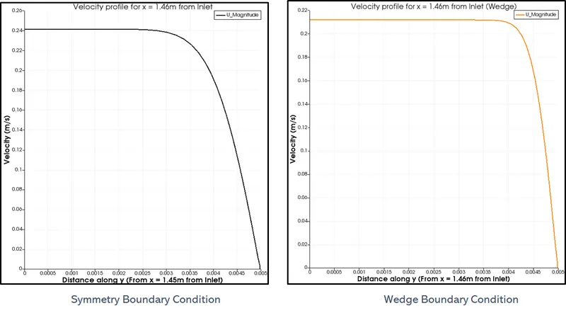
- `U_(max)` for Symmetric BC = 0.212 m/s
- `U_(max)` for Wedge BC = 0.241 m/s
Pressure profile along the diagonal length of y
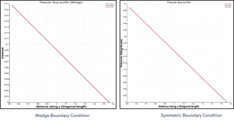
- `p_(max)` for Symmetric BC = 0.169 bar
- `p_(max)` for Wedge BC = 0.27 bar
Shear-stress profile along the diagonal length of y
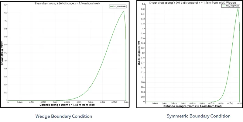
- `tau_(max)` for Symmetric BC = 0.382N/m
- `tau_(max)` for Wedge BC = 0.221 N/m
________________________________________________________________________________________________________________________________________________________-
2. For `25^circ`wedge angle
Velocity profile at x = 1.46m from Inlet
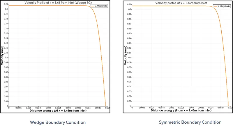
- `U_(max)` for Symmetric BC = 0.2089 m/s
- `U_(max)` for Wedge BC = 0.2091 m/s
Pressure profile along the diagonal length of y
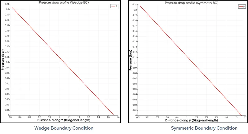
- `p_(max)` for Symmetric BC = 0.209 bar
- `p_(max)` for Wedge BC = 0.205 bar
Shear-stress profile along the diagonal length of y
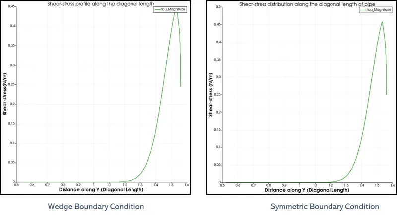
- `tau_(max)` for Symmetric BC = 0.46N/m
- `tau_(max)` for Wedge BC = 0.449 N/m
___________________________________________________________________________________________________________________________________________________
2. For `45^circ`wedge angle
Velocity profile at x = 1.46m from Inlet
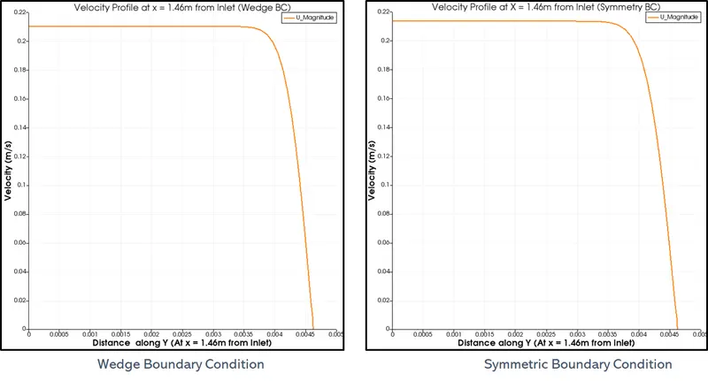
- `U_(max)` for Symmetric BC = 0.210 m/s
- `U_(max)` for Wedge BC = 0.213 m/s
Pressure profile along the diagonal length of y
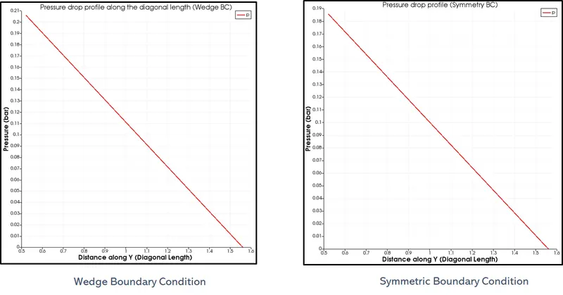
- `p_(max)` for Symmetric BC = 0.185 bar
- `p_(max)` for Wedge BC = 0.205 bar
Shear-stress profile along the diagonal length of y
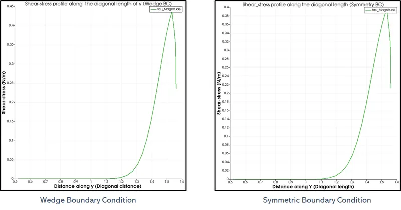
- `tau_(max)` for Symmetric BC = 0.39 N/m
- `tau_(max)` for Wedge BC = 0.45 N/m
Conclusion :
1. For greater wedge angles
- Accuracy is better
- Compromise is compuatational time
2. Symmetric Boundary condition nears the analytical value slightly closer than Wedge Boundary Condition