Manual Mid surfacing and Shell meshing on Automotive Tyre Boot floor panel
AIM : To Extract mid surface, geometry clean up and create the two dimensional mesh for the given flooor panel according to the given quality criteria by using HYPERMESH
THEORY :
STEPNEY FLOOR PANEL
A structural shear panel for forming a floor panel for support by a vehicle frame is formed by a composite of top and bottom sheets and a core with a vacuum infused resin. The core is formed of top and bottom layers each formed from a honeycomb panel defining an array of hexagonal tubular cells with walls which extend in the thickness direction filled with a foam material. A third layer is located between the first and second layers and is formed of a material such as foam, rubber or cork which is free from tubular cells in the thickness direction and free from rigid structural members in the thickness direction to reduce communication of sound through the panel.
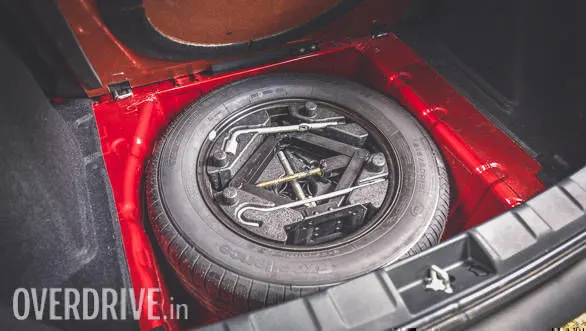
SPARE TYRE FLOOR PANEL
SHEET METAL:
Sheet metal is metal formed by an industrial process into thin, flat pieces. Sheet metal is one of the fundamental forms used in metal working, and it can be cut and bent into a variety of shapes. Countless everyday objects are fabricated from sheet metal. Thicknesses can vary significantly; extremely thin sheets are considered foil or leaf, and pieces thicker than 6 mm (0.25 in) are considered plate steel or "structural steel".
FEA: FEA is a FINITE element analysis is a numerical method for solving problems of engineering and mathematical physics.
GIVEN MODEL: First we have to extract mid surface and then mesh this component by 2D mesh as per the given quality criteria.
KEYWORDS: Import model in hyper mesh, Check for geometry clean up, extract mid surface, meshing, check for free edges, Assign thickness, Check for normal .
ABSTRACT: In this stepney floor panel of the Door is taken for the pre-processing stage of CAE. The pre-processing of this model is done by using HYPERMESH WORK software. Import the model to HYPERMESH, check for geometry clean up now extract mid surface and shell meshing, check for free edges and assign thickness for given STEPNEY FLOOR PANEL.
METHODOLOGY:
- Import given model to HYPERMESH.
- Delete solids.
- Check for geometry clean up.
- Toggling of lines.
- Mid surface Extraction.
- Assign quality criteria.
- Explain quality criteria.
- Meshing.
- Quality error's clean up.
- Check for free edges.
- Check for normal
- Assign different thickness.
Why mid surface extraction is needed?
MId surface meshing is opted for the components where the geometry thickness is small when compared with span length of the components, so if you see most of the automobile structures are of sheet metal and plastics, where the length of the component is large when compared to the elements through properties on components method and the elements thickness is assigned half on top direction and half on bottom direction. mathematically; Half on the + Z and other half on - Z directions.
Why meshing is needed on extracted mid surface?
FEA stands for the finite element analysis which means that elements are analysed and integrated over a region to derive the final result. so, in a continuous member, which in reality are everything starting from a pin to automotive parts. there are infinite nodes and it’s not possible to solve an infinite equation. so meshing is carried out so that we can discreting that continuous member into number of finite nodes. and hence go for solving the equations. after that interpolate the results for entire domain.
Now import the given model i.e., floor panel it’s a sheet metal component. so here we need to extract mid surface and perform 2D mesh for the given quality criteria using HYPERMESH software Version 20.
|
SL.NO |
QUALITY CRITERIA |
VALUE |
|
1 |
TARGET LENGTH |
5 |
|
2 |
MINIMUM LENGTH |
2 |
|
3 |
MAXIMUM LENGTH |
8 |
|
4 |
ASPECT |
5 |
|
5 |
WARPAGE |
15 |
|
6 |
SKEWNESS |
45 |
|
7 |
MINIMUM QUAD ANGLE |
45 |
|
8 |
MAXIMUM QUAD ANGLE |
135 |
|
9 |
MINIMUM TRIA ANGLE |
20 |
|
10 |
MAXIMUM TRIA ANGLE |
120 |
|
11 |
TRIA PERCENTAGE |
10 |
PROCEDURE:
STEP 1: Import model to HYPERMESH
STEP 2: Delete solids
STEP 3: Geometry clean up
STEP 4: Toggling of lines
STEP 5: Mid surface Extraction
STEP 6: Assign quality criteria
STEP 7: Explain quality criteria
STEP 8: Meshing
STEP 9: Quality error's clean up
STEP 10: Check for free edges
STEP 11: Check for normal
STEP 12: Assign different thickness
STEP 1: IMPORT MODEL TO HYPERMESH
Since we are importing a CAD geometry, the format will be either of the two industrial accepted standards:
STEP (Standard for the Exchange of Product data).
IGES (Initial Graphics exchange specification).
When selecting the file for import be sure to check if it is. STEP or .IGES files.
Import the geometry file to hyper work
For open
Go to File >> Import >> Select geometry >> Open the model >> Click the model >> Import
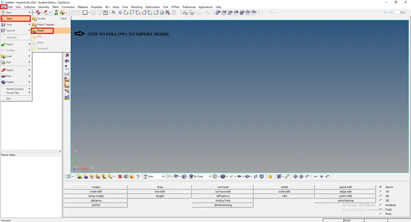
IMPORTING MODEL
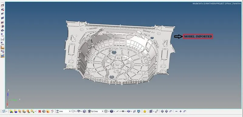
MODEL IMPORTED INTO HYPER WORK
STEP 2: DELETE SOLIDS
We only have to work on the geometry, so before inspection check for solids and delete if there are any.
Delete [F2] >> Solids >> Select by box selection >> Delete Entity
Another way to check for solids is by switching the view from AUTO MODE to TOPO MODE.
If the model is highlighted in GREEN that means solid is present.
From the image below, we can confirm that there are no solids present in the model
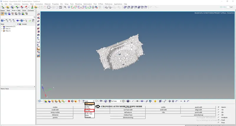
SWITCHING AUTO MODE TO TOPO MODE
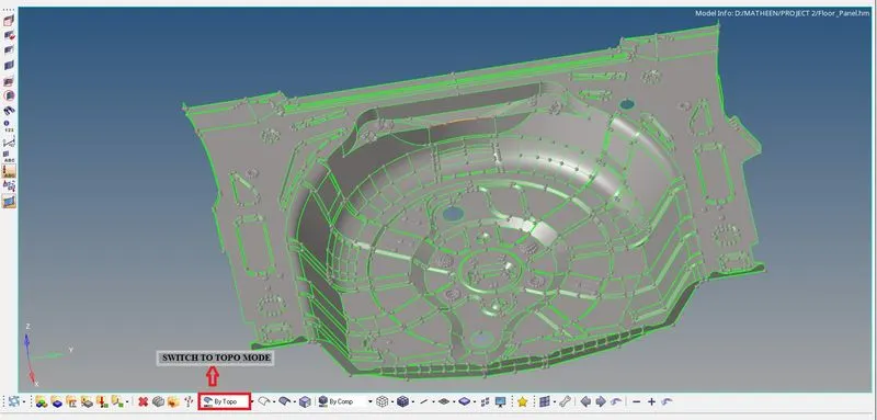
TOPO MODE
As we see the above picture and say that here we don't have and solid surface present in this model
STEP 3: GEOMETRY CLEAN UP
Once the model is imported move to geometry clean up just to check whether there any extra surface or free edges or missing surface will present or not
We should also check for any geometric deformations, such as:
Surface deformations
Free edges
Connectivity error
Now to check for errors
Go to visualize panel >> Disable shared edges and all except free edges
VISUALAIZE PANEL >> Switch ON WIRE FRAME MODE >> Now we are able to see the errors
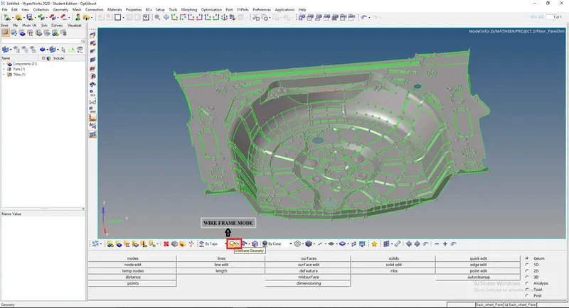
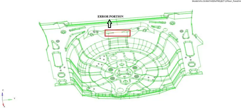
GEOMETRIC ERROR'S
Filling Gaps on Parent Geometry
As we are trying to get an auto mid, the geometry is should be a closed volume.
Therefore, we have to close the gaps (free edges) before generating an auto mid.
The gaps are very small and hard to find across the geometry. So, we can use visualization options.
In Visualization options, we can only turn on the free edges and turn off the shared, non-manifold and supressed lines.
For narrow gaps, we can toggle edge and fix them:
Geom > Quick edit [F11] > Toggle Edge > Lines (Select)

QUICK EDIT TAB
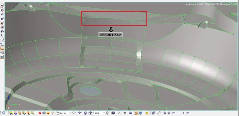
TOGGLED THE FREE EDGES
STEP 4: TOGGLING OF LINES
Toggling the line which ever is failing for minimum quality criteria
If we want to Toggle a particular line:
Toggle Edge > Right Click on the line
If we want to untoggled a line:
Toggle Edge > Left click on the line
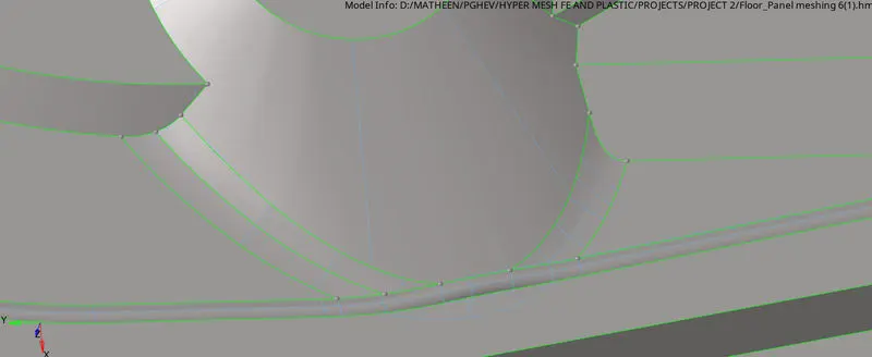
TOGGLED LINES (BLUE LINES)
STEP 5: MID SURFACE EXTRACTION
Here first we have check for the thickness of the given door model
This is sheet component so this model has same thickness
Here we have to check each and every part thickness to take MID
CHECK FOR THE THICKNESS
As we are generating a mid-surface from the geometry, we have to check for the thickness.
Check for dimensions at various regions to ensure if the component has uniform or varying thickness.
We cannot depend on Distance (F4) to check for thickness on sheet metal component as it only takes the dimensions at the edges.
The best option is to project nodes on either side of the surface and measure between the nodes to get thickness of the component. [ Shortcut: Shift + F7]
First add temp node to the surface
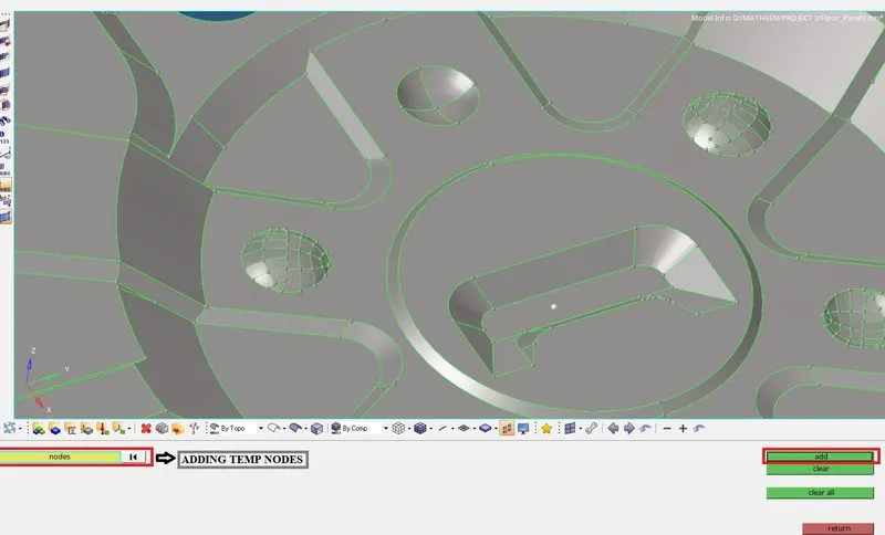
TEMP NODE ADDED
Tools >> Project >> To Surface >> Nodes >>Duplicate >> Select top Surface >> Select bottom surface >> Surface normal
Now project node to check a thickness of component as shown below
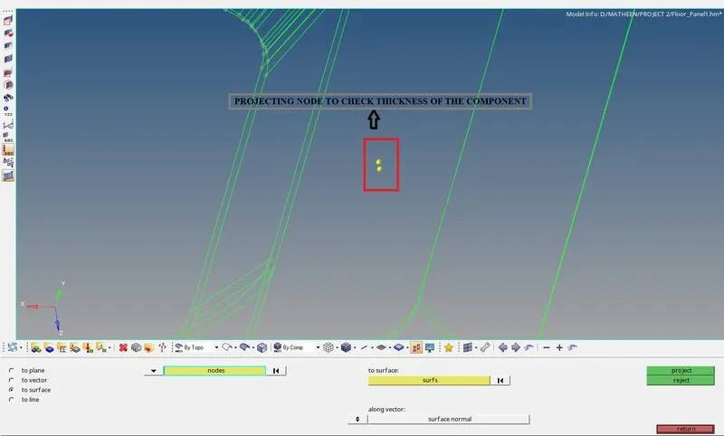
PROJECT TAB
Measure the distance between two nodes as shown below fig
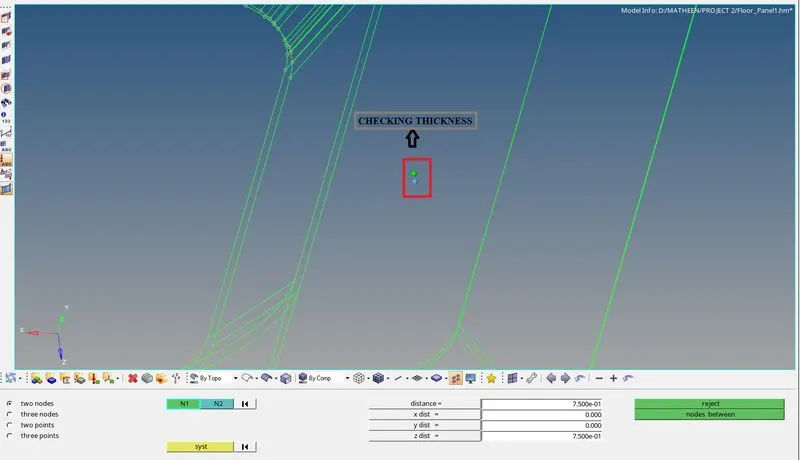
MEASURING THICKNESS OF THIS COMPONENT
As we now this a sheet metal component
The thickness of the component is same
To extract a proper or best mid surface we always prefered manual offset
But in this geometry has many sweeps and features that the user has to manually select the surfaces and there would be chances of missing some surface.
Therefore, I went with the Offset + Planes + Sweeps option to extract the mid surface:
Geom > Mid surface > Auto Mid surface > Extraction process (Offset + Planes + Sweeps) > Auto Extraction (Closed Volume) > Surfs (Displayed) > Extract
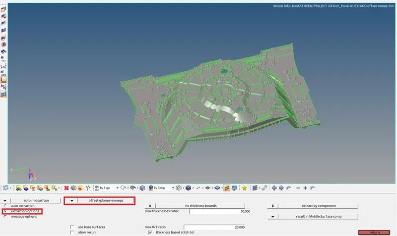
AUTO MID SURFACE
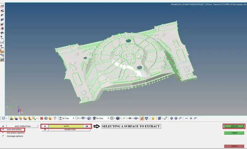
SELECTING SURAFCE TO EXTRACT
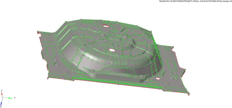
EXTRACTED MID
The extracted mid surface will be assigned to a new collector that is automatically created by Hyper mesh.
we can Rename the component if we wish to: "Mid surface".
Right Click on component > Rename
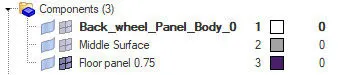
CREATED NEW COMP
GEOMETRY CLEAN UP FOR MID SURFACE:
Fixing Deformed Features
Due to the complexity of the feature the Solver is not able to generate a clean mid surface. This leads to deformations, overlapping surfaces and connectivity errors.
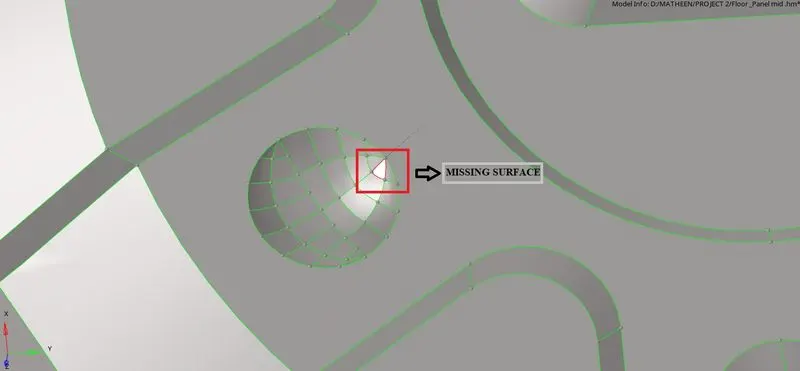
MISSING SURFACE
Upon trying manual clean up by Releasing the point and toggling, the flat surfaces get deformed.
Therefore, the best option is to delete the feature and position similar feature to this region.
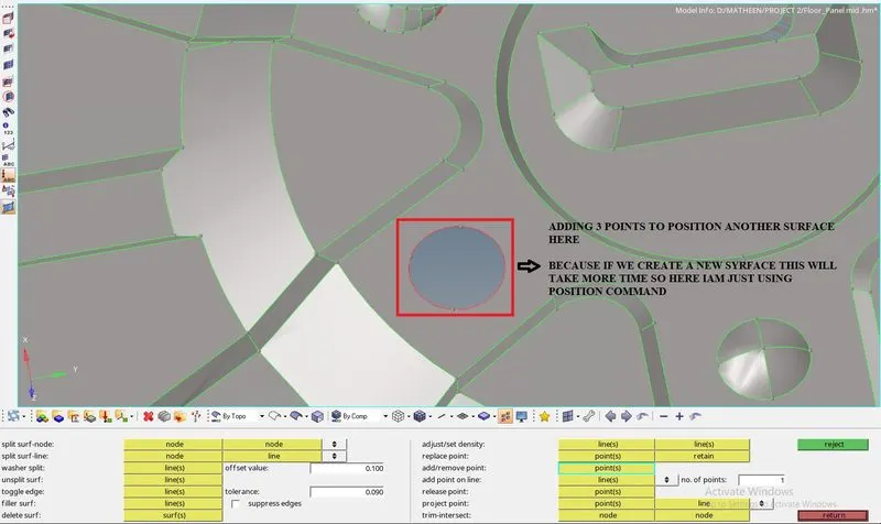
ADDING 3 POINTS
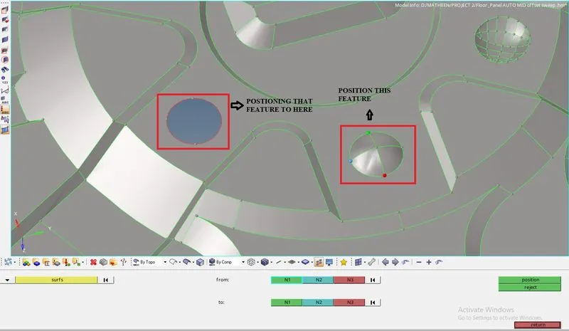
POSITIONING THE SIMILAR SURFACE
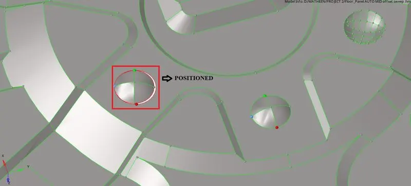
POSITIONED THE SURFACE
Now we can see from the above picture there is a gap after positioning
So, here we have to move the surface to fit in perfect postion
So, for that
Go to translate command (SHIFT + F4) >> Select the surface >> Select N1,N2 >> Translate
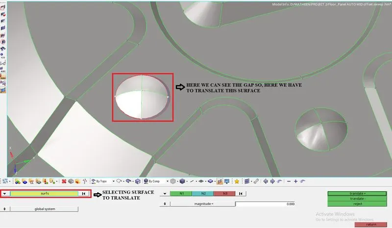
TRANSLATE COMMAND
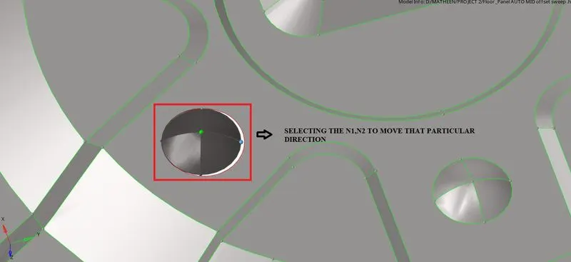
MOVING THE SURFACE
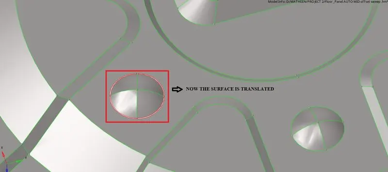
SURFACE MOVED USING TRANSLATE COMMAND
Now from the above picture we can see that there are free edges
So, here we have to toggle those free lines to get shared edge
Go to Quick edit >> Toggle >> Select line toggle
If we want to Toggle a particular line:
Toggle Edge > Right Click on the line
If we want to untoggled a line:
Toggle Edge > Left click on the line
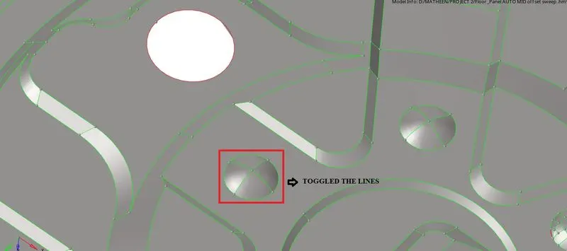
TOGGLED LINES
Creating a midline to avoid Minimum Length
From measuring the dimensions of the rib (by Distance - F4), it is evident that the element is going to fail for minimum length.
To avoid minimum length error we have to defeature the rib by creating a midline between the edges.
We can create a midline using MID LINE UNDER LINES option:
Geom >> Lines >> Select 1st line >> Select 2nd line >> Create
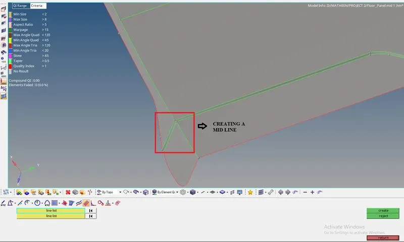
CREATING MID LINE
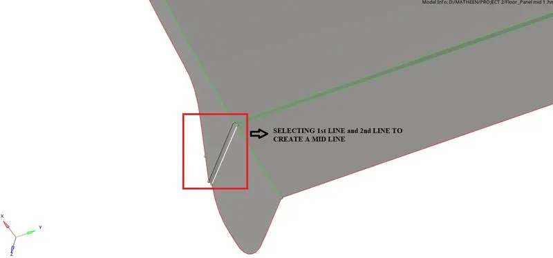
SLECTING 1st LINE AND 2nd LINE
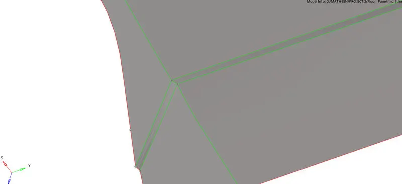
MID LINE CREATED
After creating mid line we have to trim that line
For that
Go to Surface edit (SHIFT + F9) >> Select trim with lines >> Select surf >> Select line >> Select normal to surface >> Trim
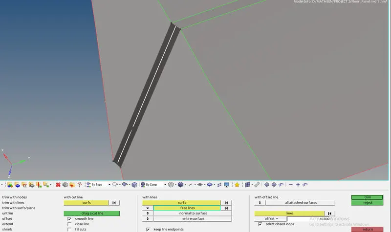
SURFACE EDIT COMMAND
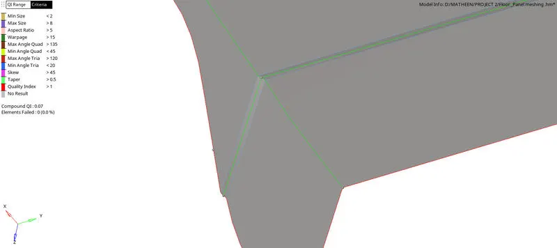
MID LINE TRIMED
Deleting small features
The features in the figure below are failing for minimum length and causing deformations on the flat’s region.
Therefore, it is best to remove these features.
Delete [F2] > Surfs (Select) > Delete Entity
Toggling of lines
We have to make sure that the length of any line or distance between any points is above the Minimum length
The fastest option for this fix is the toggle edge which is a tool under quick Edit [F11]
Quick Edit > Toggle Edge > Left click to Toggle
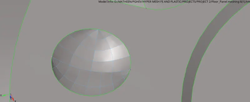
TOGGLED LINES
STEP 6: ASSIGN QUALITY CRITERIA
Assign quality criteria for a given model
Go to preferences >> criteria file setting >> Enter the values >> Apply >> Ok
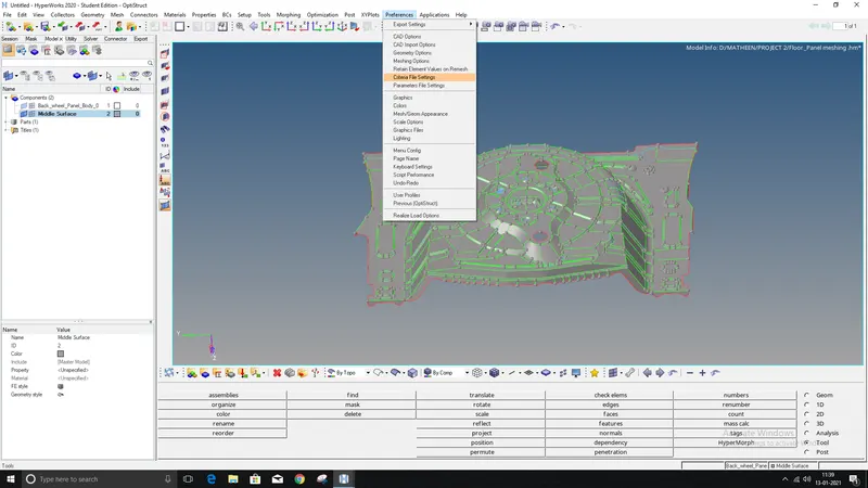
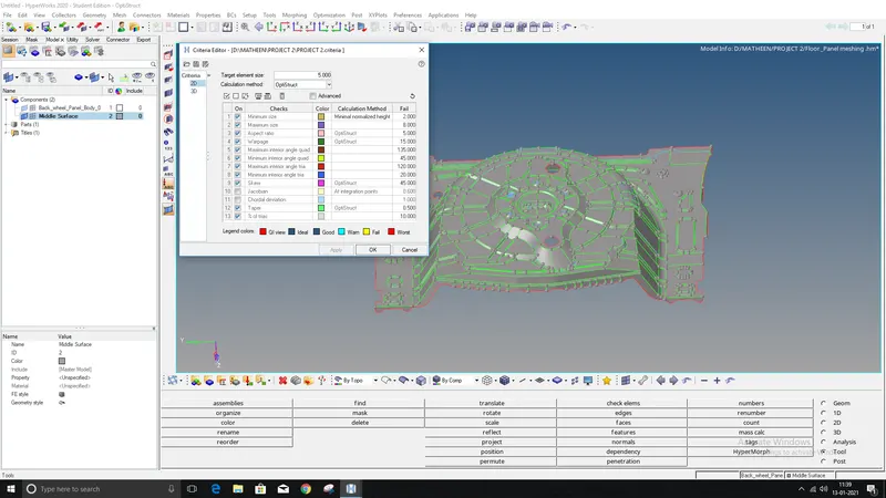
QUALITY CRITERIA
STEP 7: EXPLAIN QUALITY CRITERIA
we will look at the 2D element quality criteria, what do they mean and how they are taking an effect in the simulation. When it comes to 2D these are some important criteria which have to be taken care of.
Why do we need to take a lot of care for these element qualities? These criteria will make us understand how much the elements are deviated from the ideal element. Since they represent the geometry during a simulation, poor elements will misrepresent the geometry and will lead to inappropriate results.
Aspect Ratio:
The aspect ratio is the ratio of Maximum length to the Minimum length.
In simple terms, when you see a quad element one side smaller than the remaining three sides then you will have your element failed for aspect ratio. Being said this, the shape of a perfect quad element has all the sides equal so the ideal value of Aspect ratio is one
Skewness:
Skewness is the quality of the elements in terms of angles.

Warpage:
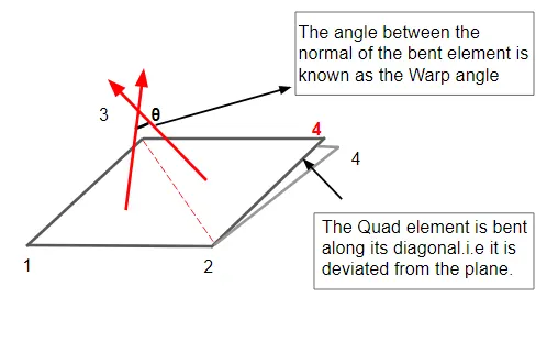
Whenever you have a quad element in two different planes then you will have your element failing for Warpage. Ideally, your element should be in a single plane, when they are in two different planes if you split the quad along the diagonal and measure the angle between the normals it will give your element Warp angle. Warp angle is the angle of plane deviation in your element which is also known as Warpage.
WARPAGE
In the above image, the element is bent in the upward direction. The element may also bend in the downward direction and cause Warpage error in the element.
When you have your element failing for warpage then the results of the simulation are going to be inaccurate. Features like fillets are more prone to have a warped element as the geometry itself will be in two different planes. Considering all these geometrical constraints and accuracy we can have a tolerance for these criteria.
Jacobian:
Every element will have its own coordinate system which is known as the Natural Coordinate system. From this coordinate system it is difficult to derive a direct solution thus these elements' natural system has to be converted to a global system.
So, in order to map the elements from its natural system to the global system, these elements have to be in ideal shape.
As we know, not all the time we can have an ideal shaped element in the geometry so a tolerance is established. This deviation of the element from the ideal shape is measured though Jacobian. The Ideal value of Jacobian is 1.
STEP 8 : MESHING
FEA stands for the finite element analysis which means that elements are analysed and integrated over a region to derive the final result. so, in a continuous member, which in reality are everything starting from a pin to automotive parts. there are infinite nodes and it’s not possible to solve an infinite equation. so meshing is carried out so that we can desecrating that continuous member into number of finite nodes. and hence go for solving the equations. after that interpolate the results for entire domain.
Mesh the given components with a given quality criteria
Rules of mesh :
For better mesh flow we need to fallow some rules :
- Opposite tria's are avoided.
- Flat surface trai's should be avoided by merging them using split.
- Avoid trai's near to hole region.
- Hole feature should be in even numbered.
- Avoid tria's at the perimeter line.
- Avoid zig-zag mesh flow.
- Avoid rotating quads.
- Divides the large surface into small parts using split for meshing.
- Defeature the area which are going to fail the quality criteria.
Now mesh the component
Go to geometry page >> Select 2D >> Select auto mesh >> Select surface >> Create
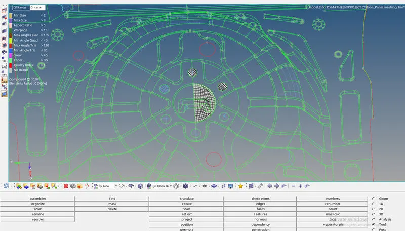
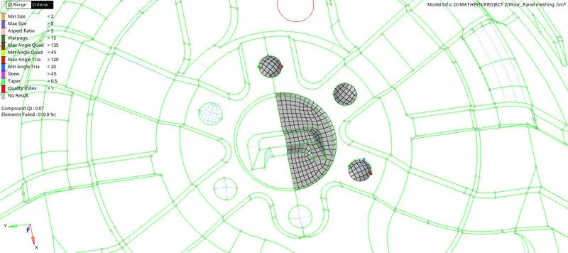
Getting good Mesh flow
After fixing for quality in a surface, give for Smooth Mesh to give a clean look.
Shift + F12 >> Elems >> Select >> Iterations = 10 >> Smooth
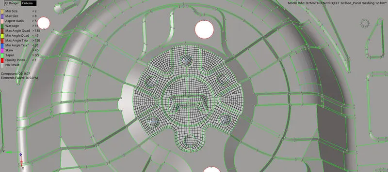
Align the Nodes across the Edges
Upon giving the Smooth Mesh, if the Edge elements cross over the shared edge and enter into the neighbouring surface we can Project [Shift + F7] them back into the current surface.
Tools >> Project >> To Line >> Select Nodes >> Normal Lines
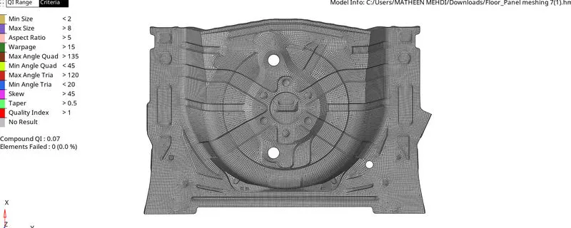
MESHING
STEP 9: QUALITY ERROR CLEAN UP
MINIMUM SIZE: Two resolve minimum length error
Go to distance command >> Select N1, N2 node >> Increase the diatance to resolve this error >> enter
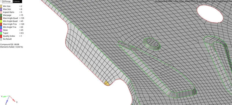
MINIMUM LENGTH ERROR
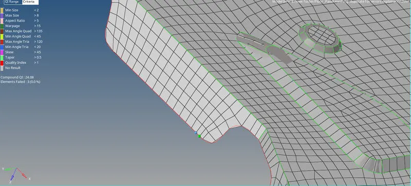
MINIMUM LENGTH ERROR CLEARED
MAXIMUM SIZE:
To resolve this max length error
Go to distance command >> Select N1, N2 node >> Decrease the diatance to resolve this error >> enter
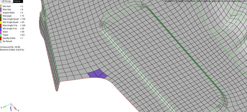
MAXIMUM LENGTH ERROR
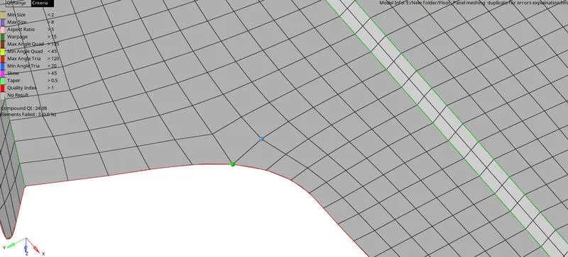
MAXIMUM LENGTH ERROR CLEARED
ASPECT RATIO :
To resolve this ASPECT RATIO error
Here we have to perform smooth option OR We can replace nodes to resolve this issue
For that
Go to Replace (F3) >> Select Node 1 >> Slelect Node 2 >> Replace
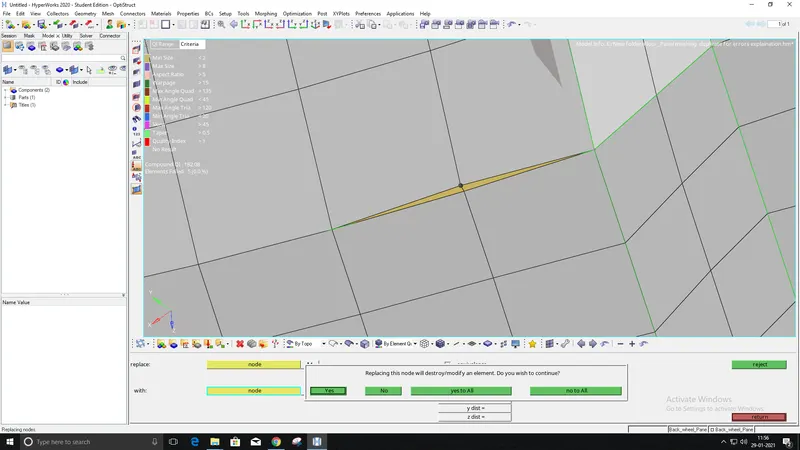
ASPECT RATIO ERROR
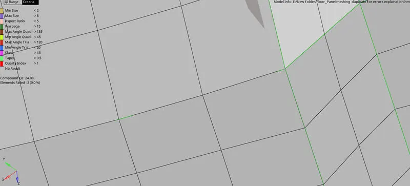
ASPECT RATIO ERROR CLEARED
WARPAGE:
Translate [Shift + F4]
This option allows us to fix warpages.
Using F10 and clicking on the warping element, check for the node at which we can use the translate option.
If it is difficult to detect the node at which the element is failing, we can mask the element alone, reverse and view it.
Mask [F5] > Elem’s > Select > Mask > Reverse all
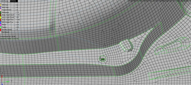
WARPAGE ERROR
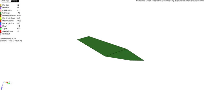
MASK ELEMENTS
Tool > Translate > Node > N1, N2 & N3 > Magnitude > Translate +/-
Nodes are the Node that you wish to translate with respect to the surface that is defined by selecting the points N1, N2 & N3 (select the rest 3 points of the quad element you have masked).
Therefore, the element itself acts as the reference plane.
Set the magnitude to the desired value, ideally keep 0.05-0.100 mm.
Depending on the direction of warpage, give translate +/- in order to bring the element close to a flat plane.
If the element warps downward, give for translate +.
If the element warps upward, give for translate -.
The picture below represents the same element that is fixed from warpage using Translate [Shift + F4] tool.
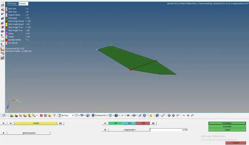
TRANSLATE COMMAND
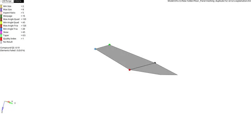
WARPAGE ERROR CLEARED
STEP 10: CHECK FOR FREE EDGE
we have to check for free edges (red lines) in the component.
Edges Tool will help us find this error:
Tool > Edges [Shift + F3] > Elem's > Select by box slection > Find edges
If free edges are present, connectivity won't be established between the surfaces.
As a result, when force is applied on any surface it won't be distributed to the neighbouring surface due to connectivity issue

CHECK FREE EDGE COMMAND
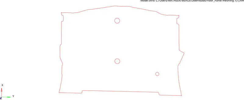
NO FREE EDGE PRESENT
Reason for fixing free edges:
If free edges are present, connectivity won't be established between the surfaces.
As a result, when force is applied on any surface it won't be distributed to the neighbouring surface due to connectivity issue.
The tolerance for Find edges and Equivalence is: 0.01mm to Minimum length
STEP 11: CHECK FOR NORMALS
After meshed the model check for vector normal
To check
Go to Tool >> Normal >> Select elements display

CHECKING NORMLAS
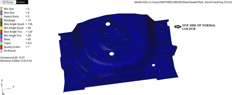
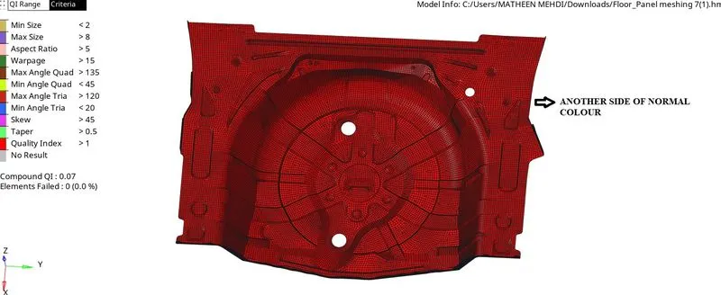
NORMALS
STEP 12: ASSIGN DIFFRENT THICKNESS
Creating Component and Property
As different elements will have different thickness, we have to assign them to their respective collectors.
First check the distance by using distance command
For that
Go to Geometry >> Distance >> Select with two points >> Check distance
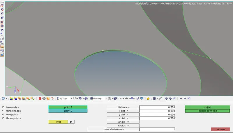
MEASURING THICKNESS
Create a new component:
Right Click on Tab Bar > Create > Component > Rename according to its respective name
Create a new property:
Right Click on Tab Bar > Create > Property > Rename as THICKNESS and its value
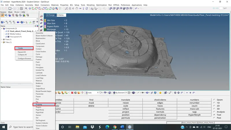
CREATING NEW PROPERTY
Enter the Avg. Thickness in the Property tab
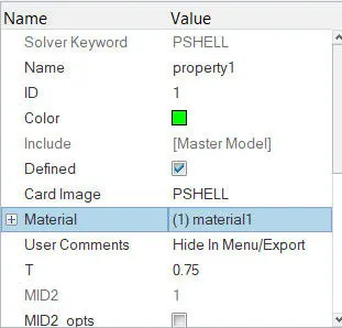
ASSIGNING THICKNESS
Assigning Property to the Component
The component/Collector just stores the component data in a file location.
If we want to store the property, we have to do it manually.
Step to Assign Property within the Component:
Right Click on Property > Assign > Property > Select > Apply > OK
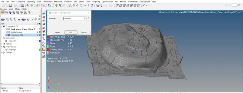
THICKNESS ASSIGNED
Now the Property is stored within that component/collector. Any surface/element stored in this component will have the same properties.
After assigning thickness
Go to select from list >> 2D traditional elements representation >> Switch to 2d detailed element representation
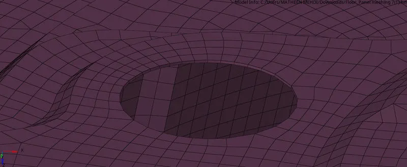
LEARNING OUTCOMES:
- Learned how to fix the geometrical errors to clean up the geometry.
- Learned how to create mid surface for each component.
- Learned how to fix quality errors.
- Learned how to meshed as per the given quality criteria.
- Learned how to reduce opposite tria's and rotating quads.
- Learned how to assign the thickness.
- Learned how to check for normal.
RESULT: All parts are successfully meshed as per the given quality criteria and Switch to 2d detailed element representation as shown in fig below
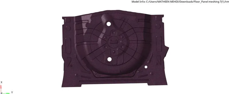
FINAL RESULTS
CONCLUSION:
In the above stepney floor panel successfully generated mid surface and meshed the model as per the given criteria here I achieved 1.8 of tria percentage which is under the given criteria and with zero quality error's