MANUAL MID SURFACING AND SHELL MESHING ON SIDE DOOR INNER PANEL
AIM : To Extract mid surface, geometry clean up and create the two dimensional mesh for the given side door inner panel according to the given quality criteria by using HYPERMESH
THEORY :
Door inner panel
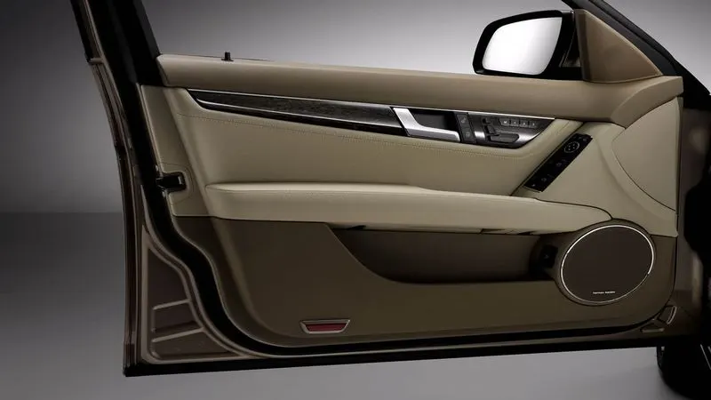
SIDE DOOR INNER PANEL
Door panels serve as an interface between the interior of the car and the inner workings of the door, and between vehicle occupants and the door. They are expected to meet a variety of design specifications regarding safety, aesthetics, and functionality. In addition, they are expected to continue the material theme of the dashboard and pillars while concealing intricate electrical and mechanical components for operating locks, windows, and other features. The door panel has evolved from a simple two-part system of the latch and simple winding mechanism to a more sophisticated enclosure. Doors currently have an inner full-width panel consisting of electronic windows, a central locking system, and speakers. These panels typically consist of a foamed core covered with either textiles or plastics.
FEA: FEA is a FINITE element analysis is a numerical method for solving problems of engineering and mathematical physics.
GIVEN MODEL: First, we have to extract mid surface and then mesh this component by 2D mesh as per the given quality criteria.
KEYWORDS: Import model in hypermesh , Check for geometry clean up, extract mid surface, meshing, check for free edges Assign thickness, Check for normals.
ABSTRACT: In this side door inner panel of the Door is taken for the pre-processing stage of CAE. The pre-processing of this model is done by using HYPERMESH WORK software. Import the model to HYPERMESH, check for geometry clean up now extract mid surface and shell meshing, check for free edges and assign thickness for given SIDE DOOR INNER PANEL.
METHODOLOGY :
- Import given model to HYPERMESH.
- Delete solids.
- Defeaturing fillets.
- Check for geometry clean-up.
- Toggling of lines.
- Mid surface Extraction.
- Assign quality criteria.
- Explain quality criteria.
- Meshing.
- Quality error's clean up.
- Check for free edges.
- Check for normal
- Assign different thicknesses.
Why mid surface extraction is needed?
MId surface meshing opts for the components where the geometry thickness is small when compared with the span length of the components, so if you see most of the automobile structures are of sheet metal and plastics, where the length of the component is large when compared to the elements through properties on components method and the thickness of the elements is assigned half on the top direction and half on the bottom direction. mathematically; Half on the + Z and another half on - Z directions.
Why meshing is needed on the extracted mid surface?
FEA stands for the finite element analysis which means that elements are analyzed and integrated over a region to derive the final result. so in a continuous member, which in reality are everything starting from a pin to automotive parts. there are infinite nodes and it's not possible to solve an infinite equation. so meshing is carried out so that we can discretion that continuous member into a number of finite nodes. and hence go for solving the equations. after that interpolate the results for the entire domain.
Now import the given model i.e side door inner panel it's a plastic component. so here we need to extract mid surface and perform 2D mesh for the given quality criteria using HYPERMESH software Version 20.
| SL.NO | QUALITY CRITERIA | VALUE |
| 1 | TARGET LENGTH | 4 |
| 2 | MINIMUM LENGTH | 2 |
| 3 | MAXIMUM LENGTH | 6 |
| 4 | ASPECT | 5 |
| 5 | WARPAGE | 15 |
| 6 | SKEWNESS | 45 |
| 7 | MINIMUM QUAD ANGLE | 45 |
| 8 | MAXIMUM QUAD ANGLE | 135 |
| 9 | MINIMUM TRIA ANGLE | 30 |
| 10 | MAXIMUM TRIA ANGLE | 120 |
| 11 | TRIA PERCENTAGE | 15 |
PROCEDURE :
STEP 1 : Import model to HYPERMESH
STEP 2 : Delete solids
STEP 3 : Defeaturing of fillets
STEP 4 : Geometry clean up
STEP 5 : Toggling of lines
STEP 6 : Mid surface Extraction
STEP 7 : Assign quality criteria
STEP 8 : Explain quality criteria
STEP 9 : Meshing
STEP 10 : Quality error's clean up
STEP 11 : Check for free edges
STEP 12 : Check for normals
STEP 13 : Assign different thickness
STEP 1: IMPORT MODEL TO HYPERMESH
Since we are importing a CAD geometry, the format will be either of the two industrial accepted standards:
STEP(Standard for the Exchange of Product data).
IGES(Initial Graphics exchange specification).
When selecting the file for import be sure to check if it is.STEP or.IGES files.
Import the geometry file to hyper work
For open
Go to File >> Import >> Select geometry >> Open the model >> Click the model >> Import
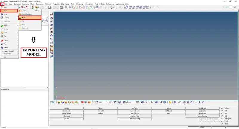
IMPORTING MODEL
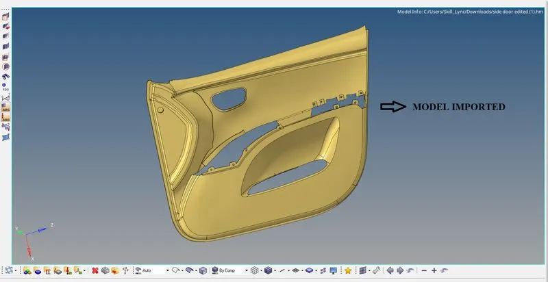
MODEL IMPORTED TO GUI
STEP 2 : DELETE SOLIDS
We only have to work on the geometry, so before inspection check for solids and delete if there are any.
Delete [F2] >> Solids >> Select by box selection >> Delete Entity
Another way to check for solids is by switching the view from AUTO MODE to TOPO MODE.
If the model is highlighted in GREEN that means solid is present.
From the image below, we can confirm that there are no solids present in the model
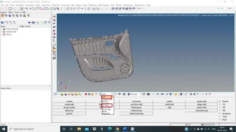
SWITCHING TO TOPO MODE
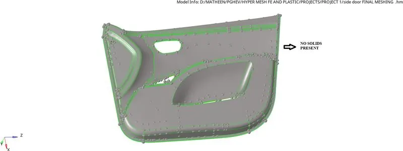
NO SOLIDS ARE PRESENT
3. DEFEATURING OF FILLETS
DEFEATURING
In hyper mesh, after you mesh a product for any kind of analysis, the end product is a meshed product. Most of the time it so happens that, some small holes or some small fillets or some small radii are left out which are not functional and unnecessary. We need to remove these unwanted features in order to obtain a final correct analysis. The process of removing these unnecessary, non-functional features is called de-featuring.
defeature all unwanted lines which is less than the given minimum length
Defeaturing of ribs
As we are performing a 2D mesh, the elements cannot capture the feature properly.
We are only going to generate a mid-surface between the two long edges of the ribs.
But the ribs have fillets which will directly affect to mid surface
Therefore, defeaturing them in order to get sharp edges is the best option to get a clean mid-surface with good mesh flow.
To defeature the fillets
Go to Geometry page >> Defeature >> Surf fillet >> Go with the surface >> Enter min and max radius as .1 and 5 >> Remove
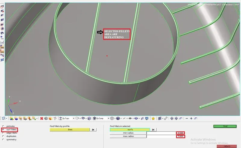
HIGHLIGHTED THE FILLETS
Select the ribs surfaces to defeature
Enter Min Radius = 0.1 mm & Max Radius = 5 mm [ This is our tolerance ]
Click Find
Upon clicking find, the solver will search for fillets within the given tolerance of the minimum and maximum radius.
The fillets within the tolerance will be highlighted.
Now click to remove the fillets as shown below
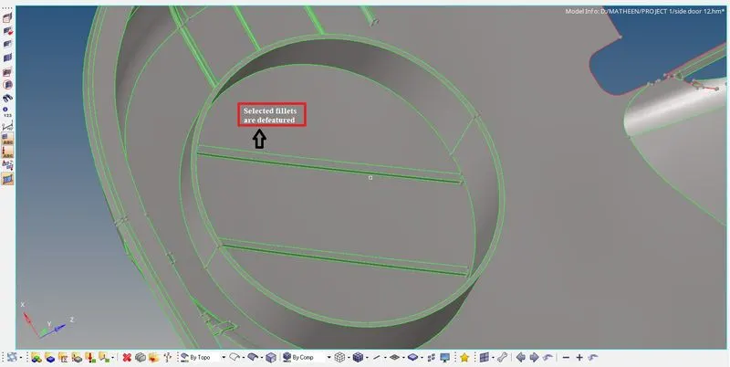
DEFEATURED RIBS
STEP 4: GEOMETRY CLEAN UP
Once the model is imported move to geometry clean up just to check whether there any extra surface or free edges or missing surface will present or not
Check for errors
To check an error
Go to visualize panel >> Disable shared edges and all except free edges
 VISUALIZE PANEL >> Switch ON WIREFRAME MODE
  >> Now we are able to see the errors
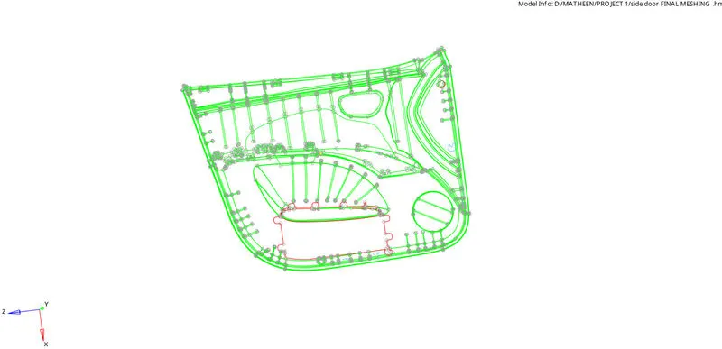
WIRE FRAME MODE
Here we don't have that many errors to clear we just have to toggle the free edges by using the toggle option
Go to Quick edit >> Toggle >> ok
While defeaturing the fillets we got errors in curve areas of fillet
The fillets can be featured only along straight edges
Some fillets extend upon curved surfaces and edges so defeaturing may not work in those regions.
Therefore, we have to manually defeature the curved fillets.
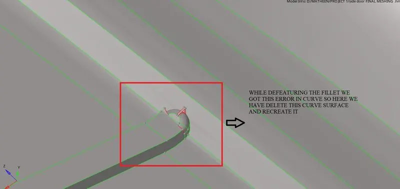
FILLET ERROR
We have to delete the curves and replace them with straight edges
Once we delete the edges a gap will be present and we will fill the gap by extending the ribs
Based on conditions there is an option to extend the ribs, Drag along Vector
DRAG ALONG VECTOR:
As the name suggest drag, we have to drag the rib along the vectors
For that
Go to Surface >>  Select drag along the vector >> Select lines to drag >> Select vector direction >> Drag +

DRAG ALONG THE VECTOR
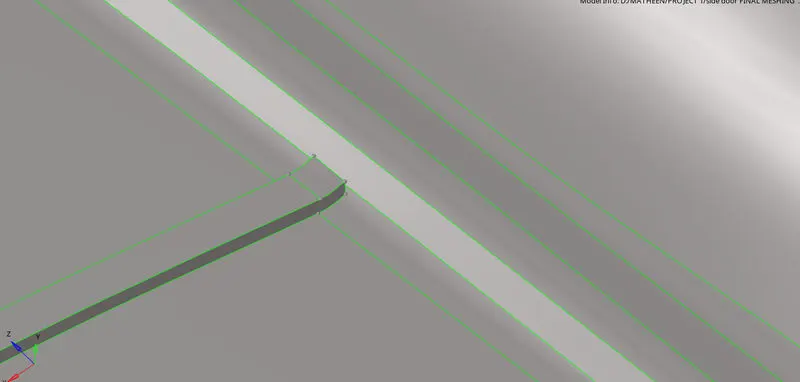
RIB CREATED
STEP 5: TOGGLING OF LINES
Fix Deformed surfaces
- Deformed surfaces occur due to the following reasons:
- Overlapping surfaces
- Connectivity issues
The error can be rectified using these below options:
- Release point & Toggle edge
- Add/Remove point & Replace point
Release point
- This allows the user to release the point causing a complex connectivity
- Once the point is released the SHARED edge turn to a FREE edge, which means the lines are disconnected from the geometry.
Geom >> Quick Edit >> Release points >> Select the points to be released.

QUICK EDIT TAB
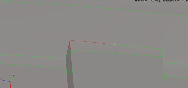
Now we have to toggle these lines
Go to Quick edit >> Toggle >> ok
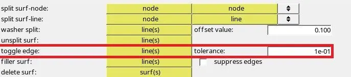
QUICK EDIT TAB
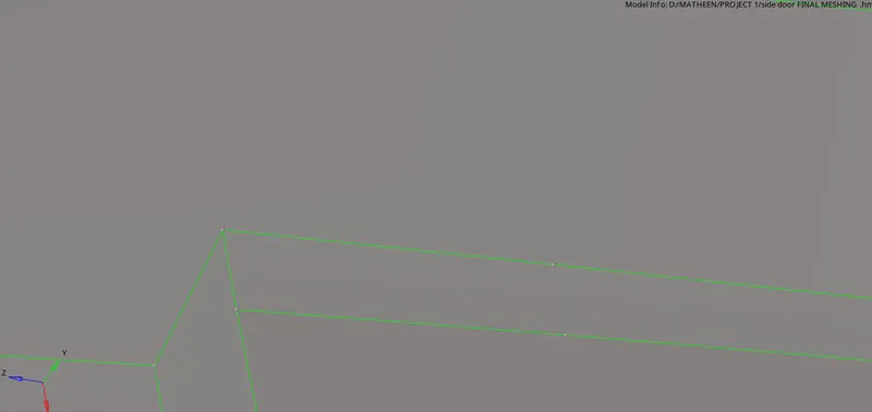
TOGGLED
If we want to Toggle a particular line:
Toggle Edge > Right Click on the line
If we want to untoggled a line:
Toggle Edge > Left click on the line
STEP 6: MID SURFACE EXTRACTION
Here first we have to check for the thickness of the given door model
This is a plastic component so this model has varying thickness
Here we have to check each and every part thickness to take MID
CHECK FOR THE THICKNESS
As we are generating a mid-surface from the geometry, we have to check for the thickness.
Check for dimensions at various regions to ensure if the component has a uniform or varying thickness.
We cannot depend on Distance (F4) to check for thickness on plastic components as it only takes the dimensions at the edges.
The best option is to project nodes on either side of the surface and measure between the nodes to get the thickness of the component. [ Shortcut: Shift + F7]
First, add temp node to the surface

TEMP NODE TAB
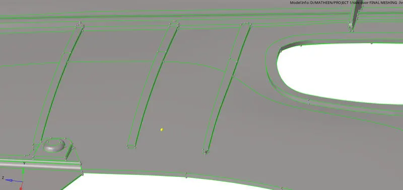
ADDED TEMP NODE
Tools >> Project >> To Surface >> Nodes >>Duplicate >> Select top Surface >> Select bottom surface >> Surface normal

PROJECT TAB
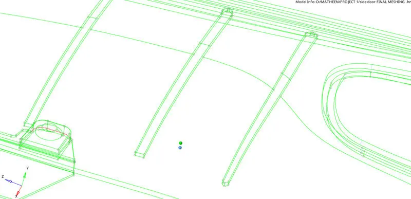
WIRE FRAM MODE TO CHECK DISTANCE
Measure the distance between two nodes as shown below fig
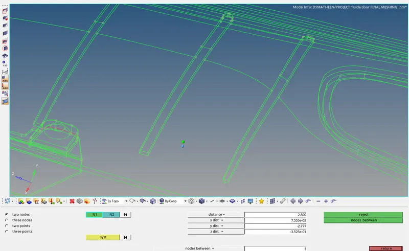
DISTANCE BETWEEN TWO NODES
This is complex geometry here auto mid surface will give you a bad result
So, here we will go with manual offset
As we know that this is a plastic component so here we have to check the thickness for each and every part
And offset these parts by manual offset
Auto offset is the most effective option if one wishes to generate an auto mid.
Due to the complexity of the design, the auto mid might not completely capture all the features and the CAE engineer might have to spend extra time in manual clean-up.
Therefore, in complex cases, it is best suited to manually offset the mid-surface.
Right Click on Tab bar >> Create >> Component >> Rename
Geometry >> Surface Edit [Shift + F9] >> Offset >> select the surface >> by Face >> Check for colour normal >> Duplicate to Current Component >> Offset = 1.4 mm >> offset
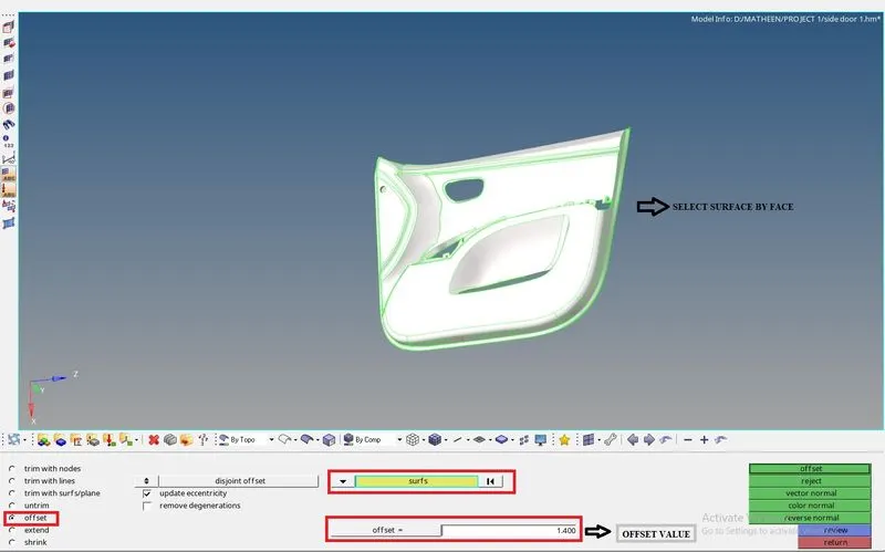
SURFACE EDIT COMMAND
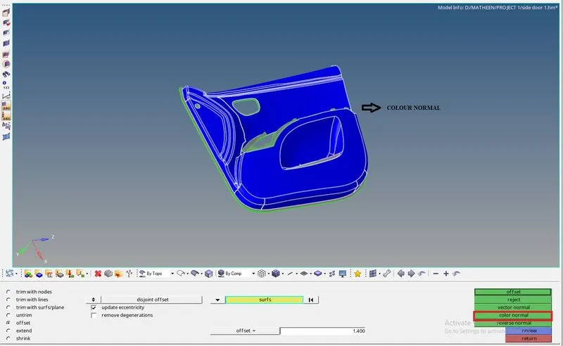
COLOUR NORMAL
Vector Normal (if outward) > Reverse Normal
- Blue indicates towards the screen or inward.
- Red indicates away from the screen or outward.
If it shows Red, give for reverse normal and it should show blue.
Colour Normal (If Red) > Reverse Normal
Colour Normal (If Blue) > Offset
Once the color normal is in BLUE give offset
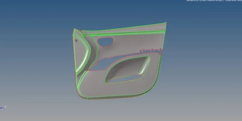
MID SURFACE GENERATED BY OFFSET COMMAND
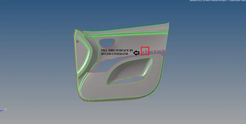
FILL THIS BY RULED COMMAND
Here we have to fill the surface to create a hole
To fill the surface
Go to surface >> Ruled >> Select lines >> Create
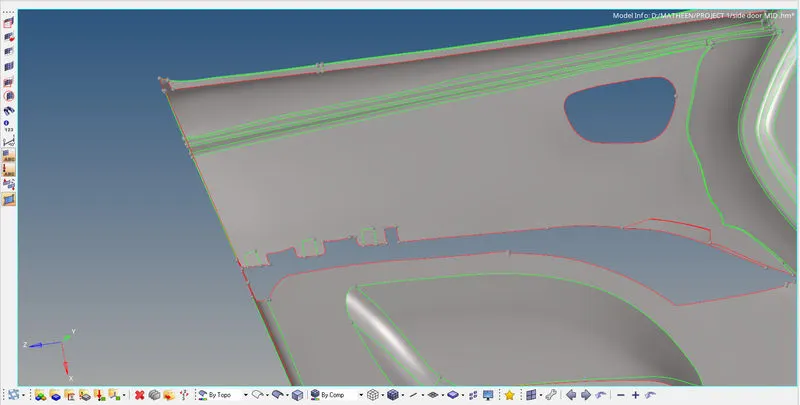
FILLED WITH RULED COMMAND
Once we fill the surface Create a hole
For that Switch on the parent geometry
Go to Surface edit (SHIFT+F9) >> trim with lines >> Select with lines in that >> Select surf: Mid surface >> Select line : Parent geometry hole >> Trim
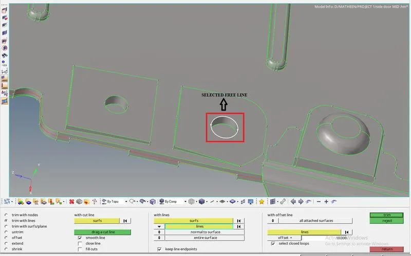
SELECTED FREE LINE TO CREATE HOLE
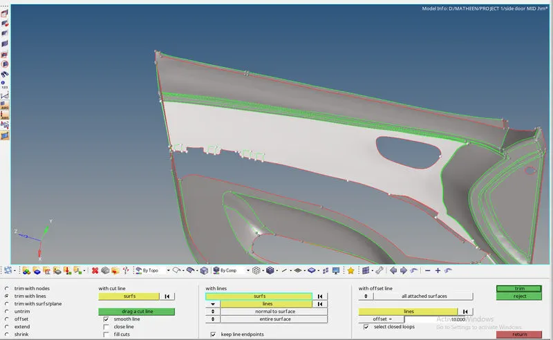
SELECTED SURFACE TO TRIM
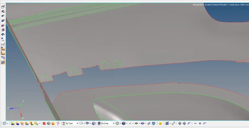
CREATED HOLE
Now we have to delete the hole area to get the required mid surface as parent geometry
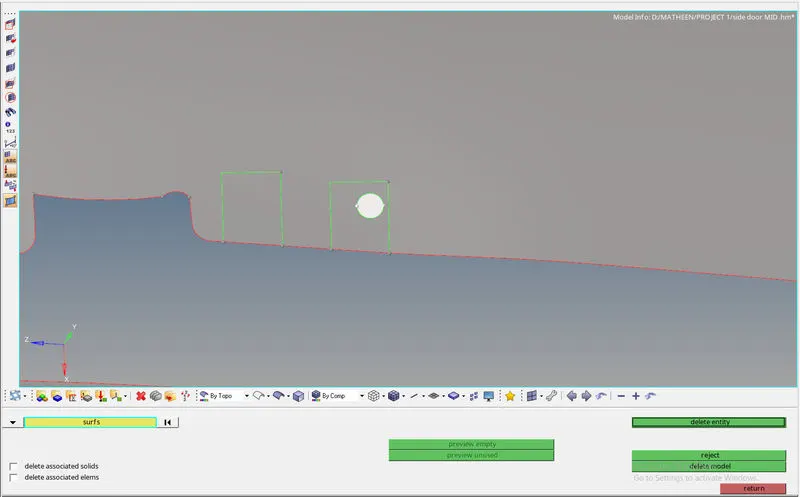
DELETED COMMAND
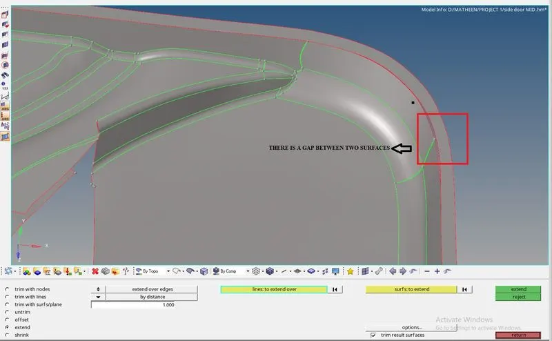
While Extracting the mid surface, we can notice that there are gaps between the extracted edges
This is due to the difference in the width of the top and bottom edges in the parent geometry.
We can fill the gap by extending one surface to the adjacent surface.
This can be done from within the Surface edit Panel [Shift + F9]:
Geometry >> Surface edit [Shift + F9] >> Extend over Edges >> To Surfaces >> Lines: To Extend Over >> Surfs: To Target > Extend
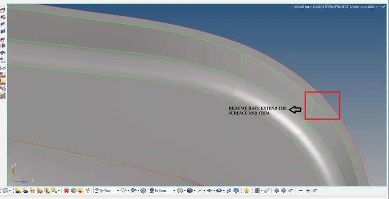
ERROR FIXED
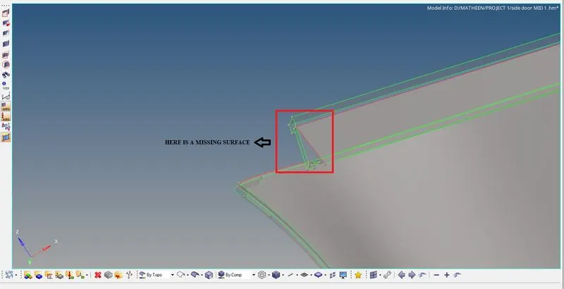
MISSING SURFACE
In the above picture, we can see that we have some missing area so, here we have to create OR extend the surface
But extend command will not work here
So, In this case, we have to use the drag option for that
Go to surface >> Drag >> along with vector >> select line >> Give N1,N2 Direction >> Enter distance >> Drag +
After dragging trim with parent geometry and delete unwanted surface
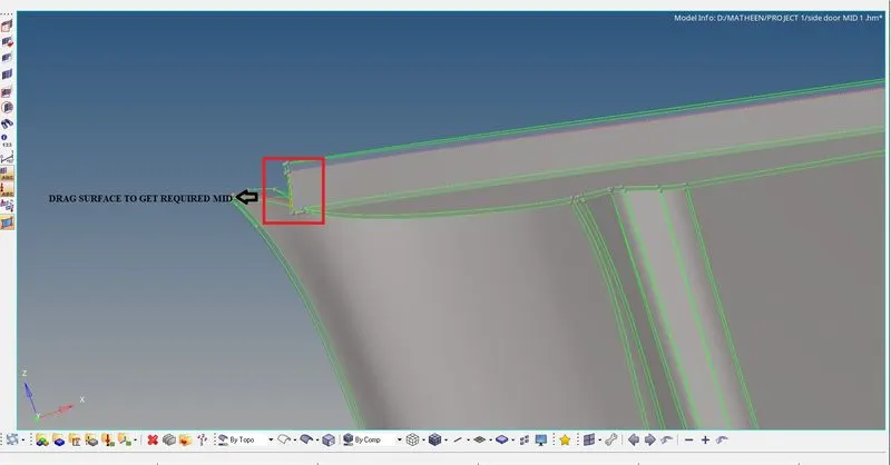
DRAGED SURFACE
EXTRACTION OF MID:
- Auto mid
- Manual mid
BY USING AUTO MID
For that
Go to Geometry >> Auto mid option >> Final edit tool >> Select Side 1 >> Select Side 2 >> Extract
BY USING MANUAL MID
For that
Go to lines >> mid lines >> select 1st line >> select 2nd line >> create
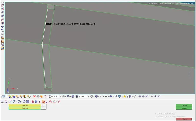
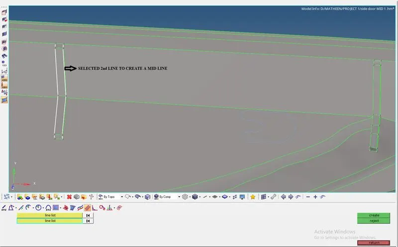
CREATING A MIDLINE
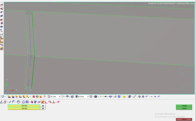
MID LINE CREATED
Now to create a rib
Go to surface edit >> trim with lines >> with lines >> select surface >> free lines >> normal to surface >> trim
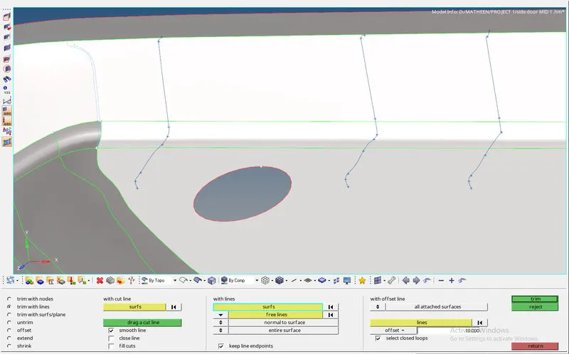
SELECTED SURFACE TO TRIM
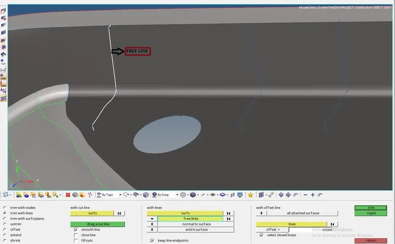
SELECTED FREE LINE
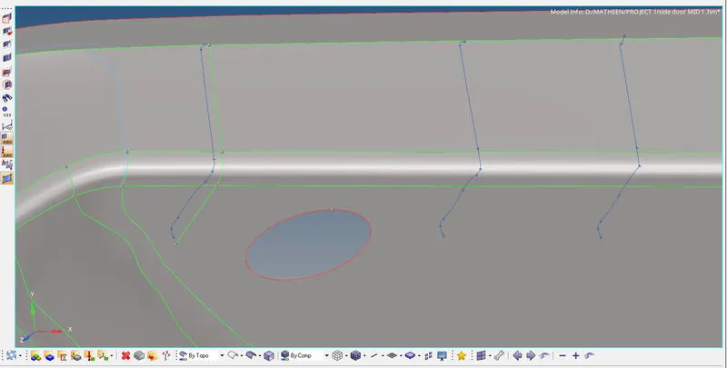
FREE LINE IS TRIMMED TO THE SURFACE
Now we have to create a new surface by using lines
Go to surface >> Ruled >> Select 1st line >> Select 2nd line >> Create a new surface
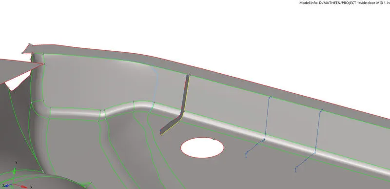
RIB IS CREATED
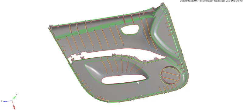
FINAL MID SURFACE
STEP 7: ASSIGN QUALITY CRITERIA
Assign quality criteria for a given model
Go to preferences >> criteria file setting >> Enter the values >> Apply >> Ok
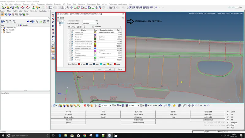
QUALITY CRITERIA
STEP 8: EXPLAIN QUALITY CRITERIA
we will look at the 2D element quality criteria, what do they mean, and how they are taking an effect in the simulation. When it comes to 2D these are some important criteria that have to be taken care of.
Why do we need to take a lot of care for these element qualities? These criteria will make us understand how much the elements deviate from the ideal element. Since they represent the geometry during a simulation, poor elements will misrepresent the geometry and will lead to inappropriate results.
Aspect Ratio:
The aspect ratio is the ratio of Maximum length to the Minimum length.
In simple terms, when you see a quad element one size smaller than the remaining three sides then you will have your element failed for aspect ratio. Being said this, the shape of a perfect quad element has all the sides equal so the ideal value of the Aspect ratio is one
Skewness:
Skewness is the quality of the elements in terms of angles.

Warpage:
Whenever you have a quad element in two different planes then you will have your element failing for Warpage. Ideally, your element should be in a single plane, when they are in two different planes if you split the quad along the diagonal and measure the angle between the normals it will give your element a Warp angle. Warp angle is the angle of plane deviation in your element which is also known as Warpage.
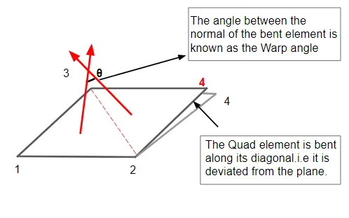
WARPAGE
In the above image, the element is bent in an upward direction. The element may also bend in the downward direction and cause a Warpage error in the element.
When you have your element failing for warpage then the results of the simulation are going to be inaccurate. Features like fillets are more prone to have a warped element as the geometry itself will be in two different planes. Considering all these geometrical constraints and accuracy we can have a tolerance for these criteria.
Jacobian:
Every element will have its own coordinate system which is known as the Natural Coordinate system. From this coordinate system, it is difficult to derive a direct solution thus these elements' natural system has to be converted to a global system.
So, in order to map the elements from their natural system to the global system, these elements have to be in ideal shape.
As we know, not all the time we can have an ideal shaped element in the geometry so tolerance is established. This deviation of the element from the ideal shape is measured through Jacobian. The Ideal value of Jacobian is 1.
STEP 9: MESHING
FEA stands for the finite element analysis which means that elements are analyzed and integrated over a region to derive the final result. so, in a continuous member, which in reality are everything starting from a pin to automotive parts. there are infinite nodes and it’s not possible to solve an infinite equation. so meshing is carried out so that we can desecrating that continuous member into a number of finite nodes. and hence go for solving the equations. after that interpolate the results for the entire domain.
Mesh the given components with a given quality criteria
Rules of mesh :
For better mesh flow we need to follow some rules :
- Opposite tria's are avoided.
- Flat surface trai's should be avoided by merging them using split.
- Avoid trai's near to hole region.
- The hole feature should be even-numbered.
- Avoid tria's at the perimeter line.
- Avoid zig-zag mesh flow.
- Avoid rotating quads.
- Divides the large surface into small parts using split for meshing.
- Defeature the area which is going to fail the quality criteria.
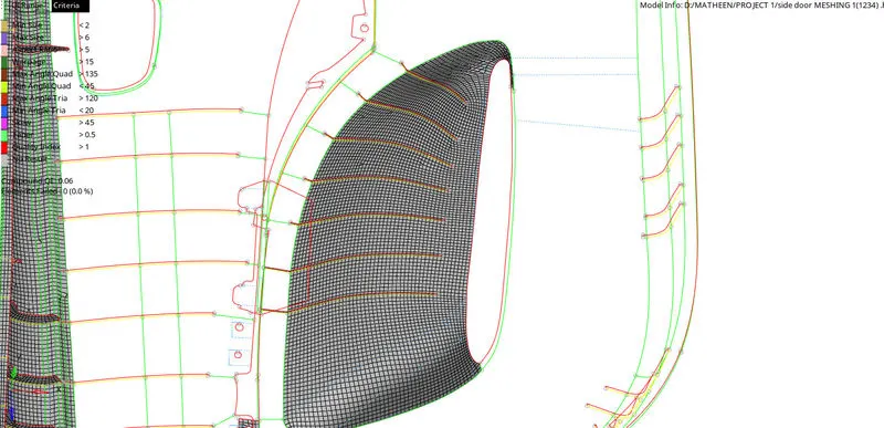
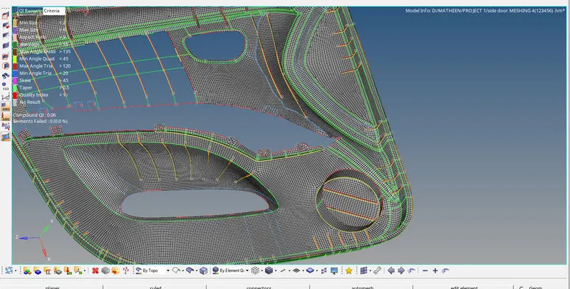
Now mesh the component
Go to geometry page >> Select 2D >> Select auto mesh >> Select surface >> Create
STEP 10: QUALITY ERROR CLEAN UP
MINIMUM SIZE: Two resolve minimum length error
Go to distance command >> Select N1, N2 node >> Increase the diatance to resolve this error >> enter
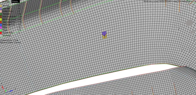
MINUMUM AND MAXIMUM ERROR

DISTANCE TAB
MAXIMUM SIZE:
To resolve this max length error
Go to distance command >> Select N1, N2 node >> Decrease the diatance to resolve this error >> enter
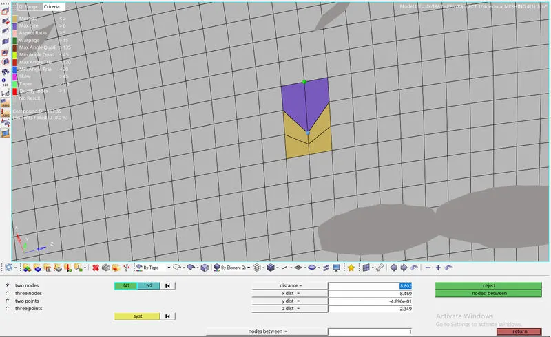
DECREASE THE DISTANCE FOR MAX ERROR
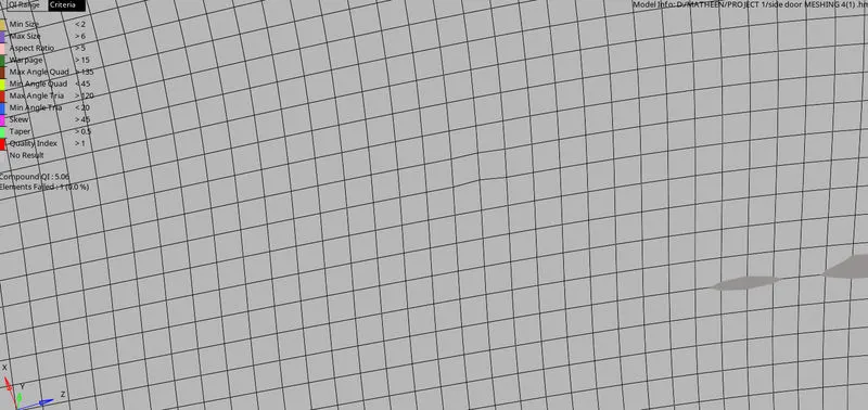
RESOLVED ERRORS
WARPAGE:
Translate [Shift + F4]
This option allows us to fix warpages.
Using F10 and clicking on the warping element, check for the node at which we can use the translate option.
If it is difficult to detect the node at which the element is failing, we can mask the element alone, reverse and view it.
Mask [F5] > Elem’s > Select > Mask > Reverse all
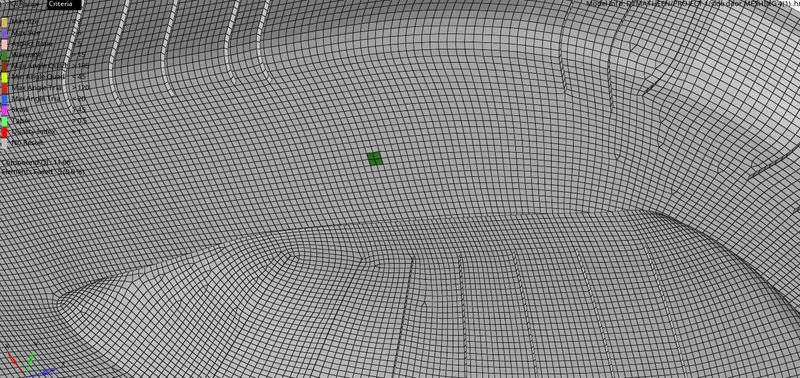
WARPAGE ERROR
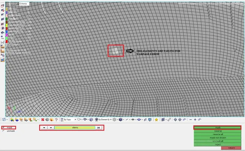
MASKING THOSE ELEMENTS
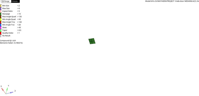
ELEMENTS MASKED
Tool > Translate > Node > N1, N2 & N3 > Magnitude > Translate +/-
Nodes are the Node that you wish to translate with respect to the surface that is defined by selecting the points N1, N2 & N3 (select the rest 3 points of the quad element you have masked).
Therefore, the element itself acts as the reference plane.
Set the magnitude to the desired value, ideally keep 0.05-0.100 mm.
Depending on the direction of the warpage, give translate +/- in order to bring the element close to a flat plane.
If the element warps downward, give for translate +.
If the element warps upward, give for translate -.
The picture below represents the same element that is fixed from warpage using Translate [Shift + F4] tool.
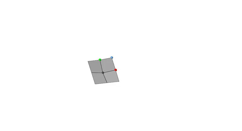
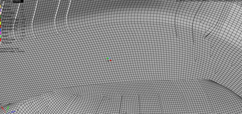
WARPAGE ERROR FIXED
STEP 11: CHECK FOR NORMALS
After meshed the model check for vector normal
To check
Go to Tool >> Normal >> Select elements display
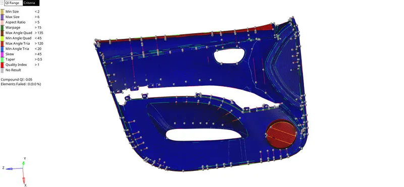
CHECKING FOR NORMALS
This is a complex model we are not able to see every time were my normals are changed
So, For that
Add a temp node where we have to reverse the normal 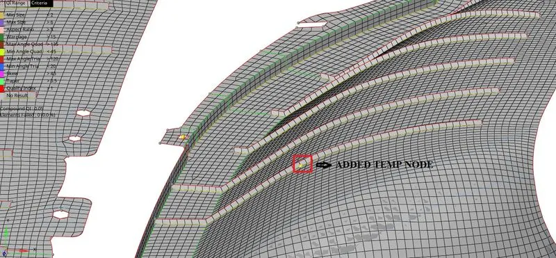
ADDED TEMP NODE
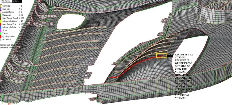
REVERSING THE NORMAL
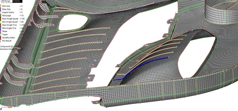
REVERSED THE NORMAL
STEP 12: CHECK FOR FREE EDGE
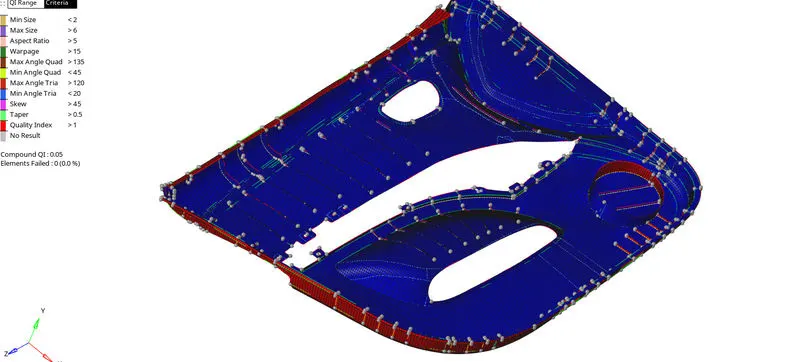
we have to check for free edges (red lines) in the component.
Edges Tool will help us find this error:
Tool > Edges [Shift + F3] > Elem's > Select by box selection > Find edges
If free edges are present, connectivity won't be established between the surfaces.
As a result, when force is applied on any surface it won't be distributed to the neighboring surface due to connectivity issues.
STEP 13: ASSIGN DIFFERENT THICKNESS
Creating Component and Property
As different elements will have different thicknesses, we have to assign them to their respective collectors.
First, check the distance by using the distance command
For that
Go to Geometry >> Distance >> Select with two points >> Check distance
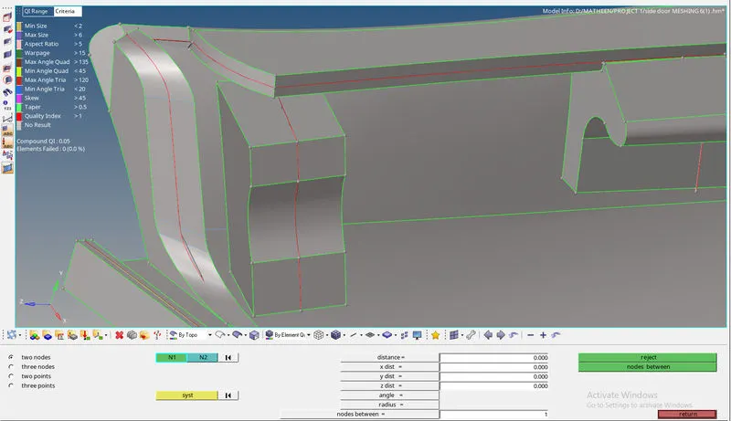
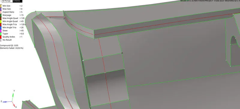
DISTANCE COMMAND
Create a new component:
Right Click on Tab Bar > Create > Component > Rename according to its respective name
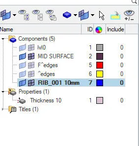
CREATED COMPONENT
Create a new property:
Right Click on Tab Bar > Create > Property > Rename as THICKNESS and its value
Enter the Avg. Thickness in the Property tab
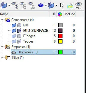
PROPERTY CREATED
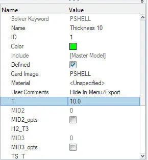
ENTERING THICKNESS
Assigning Property to the Component
The component/Collector just stores the component data in a file location.
If we want to store the property, we have to do it manually.
Step to Assign Property within the Component:
Right Click on Property > Assign > Property > Select > Apply > OK
Now the Property is stored within that component/collector. Any surface/element stored in this component will have the same properties.
For assigning different thickness
Go to Organise command >> Select elems to organise >> select current component >> move
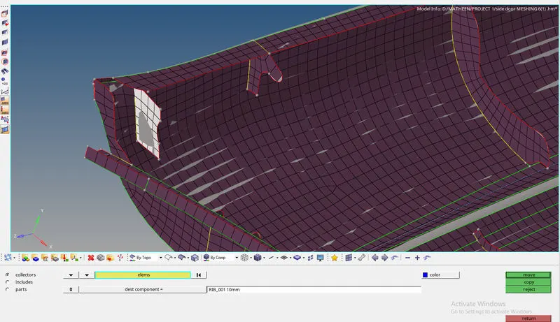
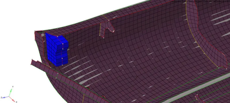
ASSIGNING THICKNESS TO THE RIB
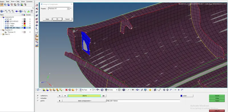
ASSIGNED THICKNESS
The same steps have to follow for other thickness too
After assigning thickness
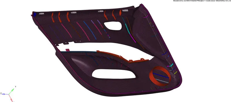
Go to select from list >> 2D traditional elements representation >> Switch to 2d detailed element representation
LEARNING OUTCOMES:
- Learned how to fix the geometrical errors to clean up the geometry.
- Learned how to create a mid surface for each component.
- Learned how to fix quality errors.
- Learned how to mesh as per the given quality criteria.
- Learned how to reduce opposite tria's and rotating quads.
- Learned how to assign the thickness.
- Learned how to check for normal.
RESULT: All parts are successfully meshed as per the given quality criteria and Switch to 2d detailed element representation as shown in fig below
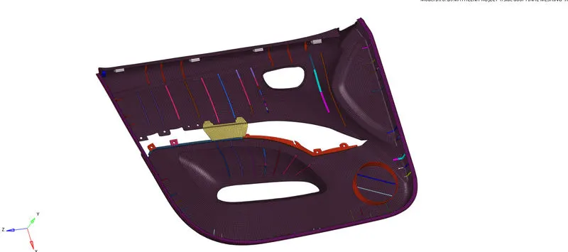
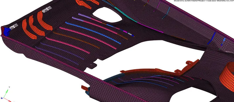
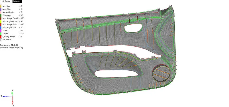
INNER DOOR PANEL HAS MESHED AND ERROR-FREE
CONCLUSION:
In the above inner door panel successfully generate mid surface and mesh the model as per the given criteria here I achieved 0.63 of tria percentage which is under the given criteria and with zero quality error's