Week 12- Final project
DEVELOPMENT OF DOOR TRIM PANEL
Objective:
1. Create the parts of door trim panel using master section.
2. Create the main tooling axis and side core axis.
3. Attach the part using enginering feature such as heat stack, flange, dog house, push pin clip, 4 way locator.
3. Perform the draft analysis on class-A surface and final component model.
Software Used:
CATIA V5.
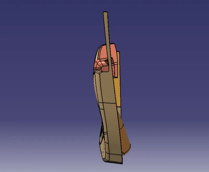
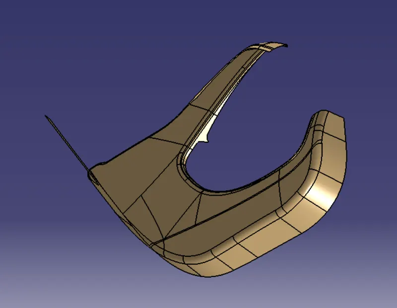
DOOR TRIM PANEL PARTS : CLASS-A SURFACE
Class-A surface are the CAD Model that given by surface developer for creation of thicken part CAD model.
Arm Rest : Class-A Surface
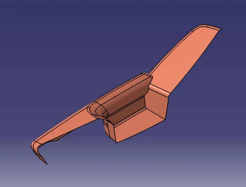
Bottle Holder : Class-A Surface
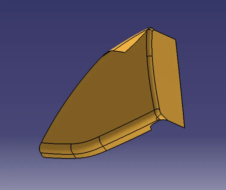
Map Pocket : Class-A Surface
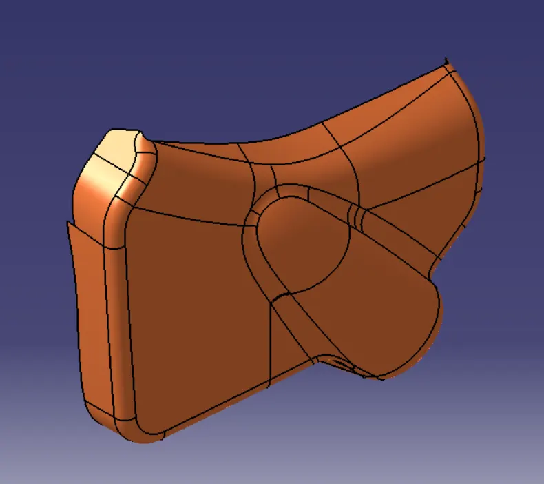
Lower Substrate : Class-A Surface
DOOR TRIM PANEL PARTS : TOOLING AXIS
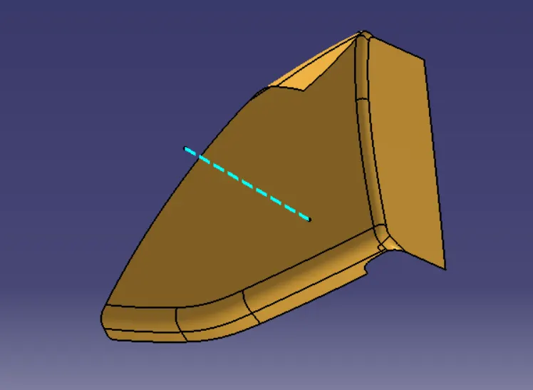
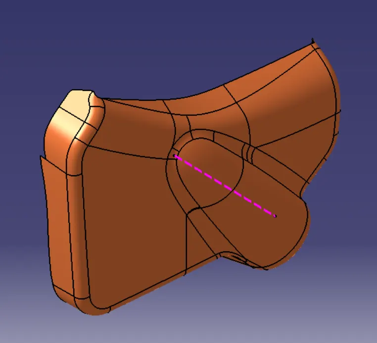
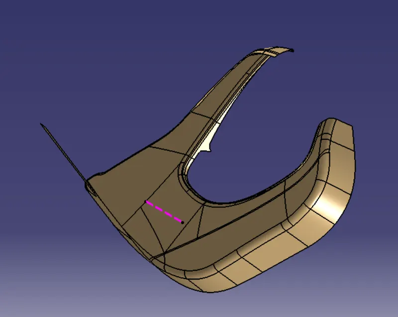
Tooling axis: The direction in which the mold or core and cavity opens is the tooling axis.
Steps to Create a Tooling Axis:
1. Create a reference tooling point on surface.
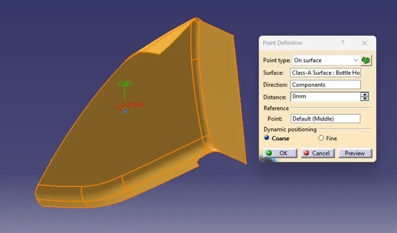
2. Create a tooling axis through a reference point in direction where a most of the surface exposed to a tooling direction.
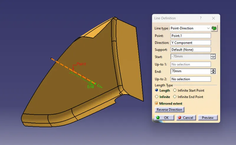
Arm Rest : Tooling Axis
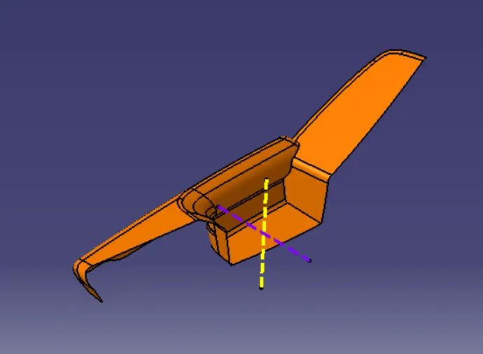
Bottle Holder : Tooling Axis
Map Pocket : Tooling Axis
Lower Substrate : Tooling Axis
DOOR TRIM PANEL PARTS : CLASS-B SURFACE
Class-B Surface is developed from class-A surface by taking a offset of class-A as per master section by using commands such as offset, extract, multiple extract, multi-sections surface, untrim, trim, join etc.
Command Used: Offser, Extract, Multiple Extract, Multi-Section Surface, Trim, Join etc.
Arm Rest : Class-B Surface
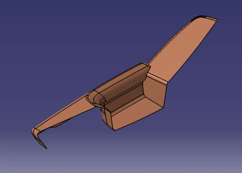
Bottle Holder : Class-B Surface
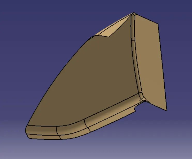
Map Pocket : Class-B Surface
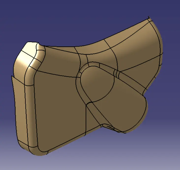
Lower Substrate : Class-B Surface
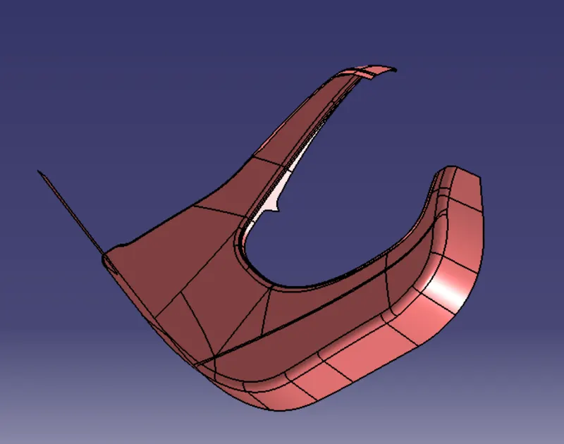
DOOR TRIM PANEL PARTS : CLASS-C SURFACE
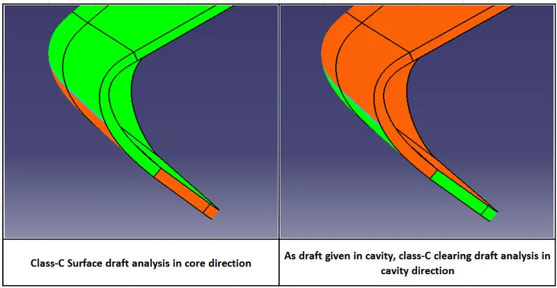
Class-C Surface is developed from class-A surface by sweeping the boundary of class-A surface with reference surface and draft direction.
Command Used: Sweep, Join, Trim.
Arm Rest : Class-C Surface
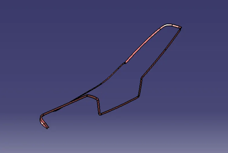
Bottle Holder : Class-C Surface
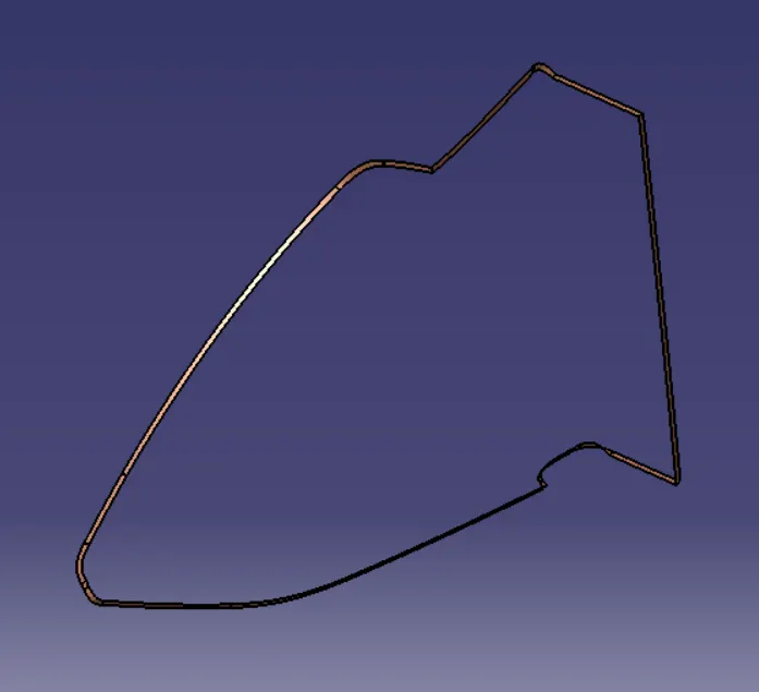
Map Pocket : Class-C Surface
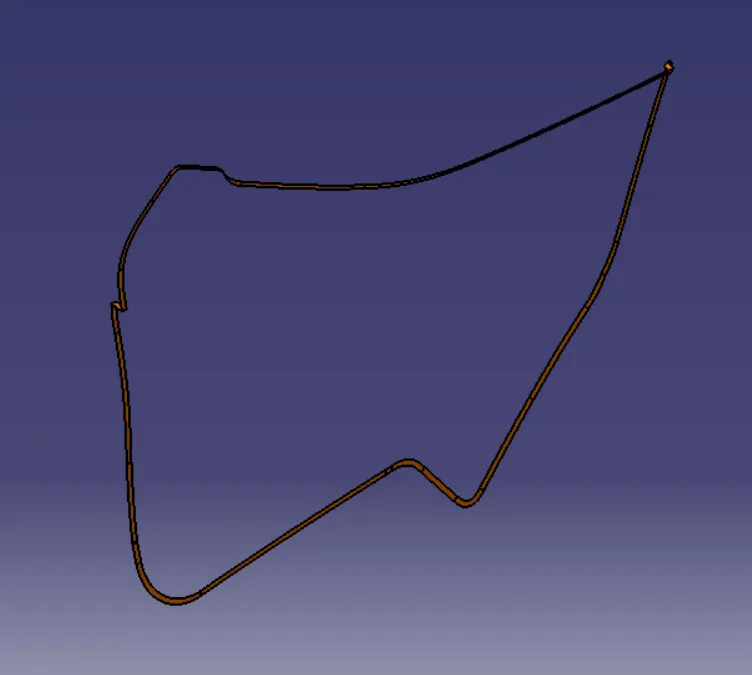
Lower Substrate : Class-C Surface
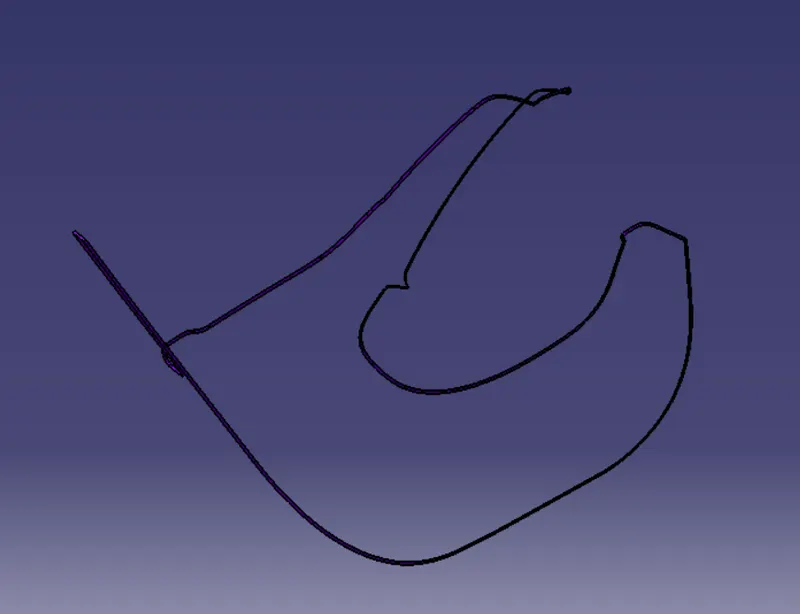
DOOR TRIM PANEL PARTS : JOIN CLASS-A & C SURFACE
Join class-A & C surface by using command trim / join.
Command Used: Trim, Join.
Arm Rest : Join Class-A & C Surface
Bottle Holder : Join Class-A & C Surface
Map Pocket : Join Class-A & C Surface
Lower Substrate : Join Class-A & C Surface
DOOR TRIM PANEL PARTS : FINAL TRIM
Finally, trim the class-B surface with joined class-A & C surface after extrapolating the class-B surface.
Command Used: Trim, Extrapolating.
Arm Rest : Final Trim
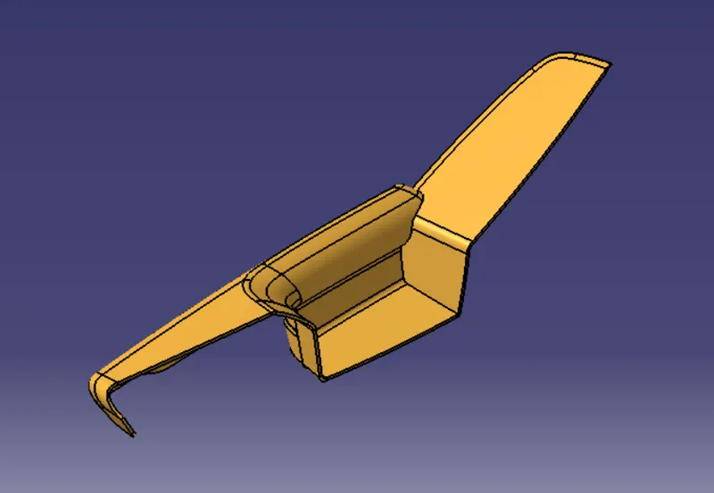
Bottle Holder : Final Trim
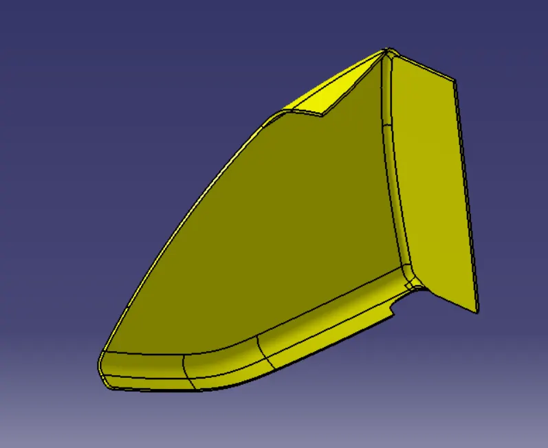
Map Pocket : Final Trim
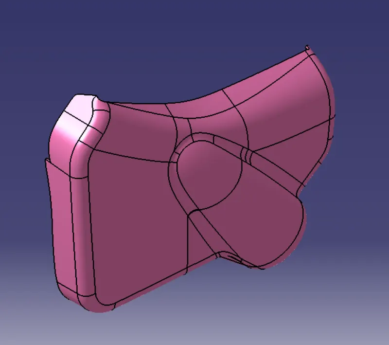
Lower Substrate : Final Trim
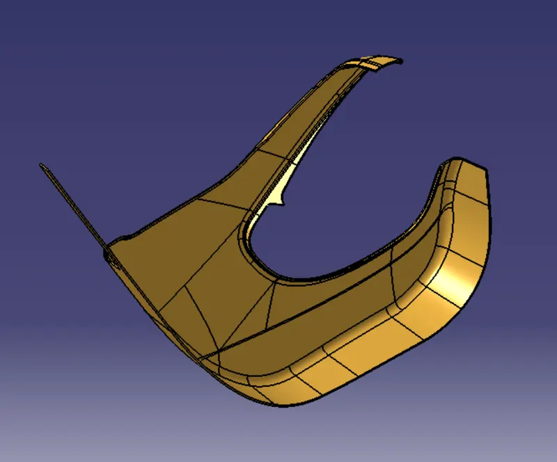
DOOR TRIM PANEL PARTS : FINAL BODY
Final body is created by closed surface on final trim.
Command Used: Closed Surface.
Arm Rest : Final Body

Bottle Holder : Final Body
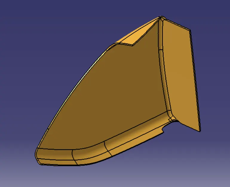
Map Pocket : Final Body
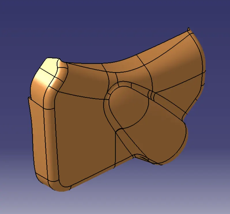
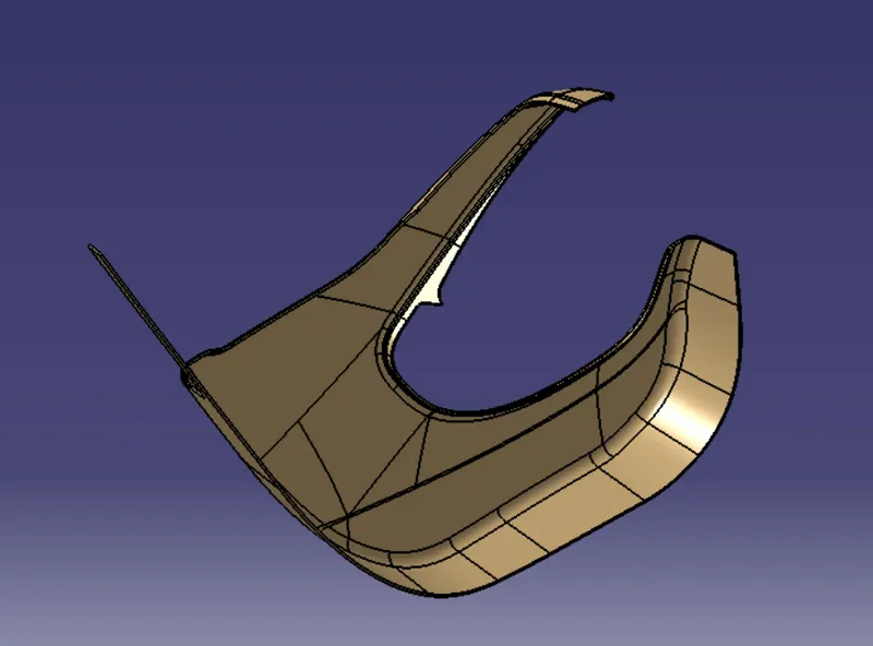
Lower Substrate : Final Body
DOOR TRIM PANEL PARTS : DRAFT ANALYSIS
Draft : The purpose of providing angles or tapered face by draft is to remove the part from the mould with ease so that it is parallel to the direction of mould release.
Steps for Draft Analysis:
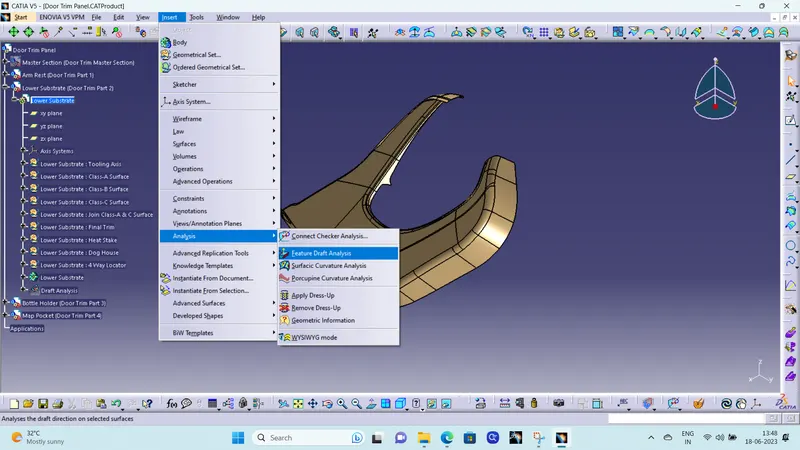
1. First go to the surface tab bar then click on Insert -> Analysis -> Feature Draft Analysis.
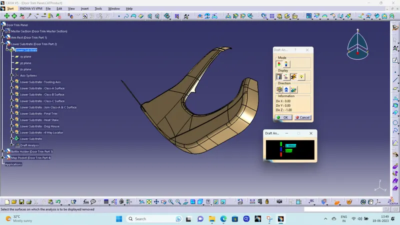
2. Then go to Customize View Parameters and check whether the material box under mesh is ticked or not. If not ticked click on the box and tick it for draft analysis.
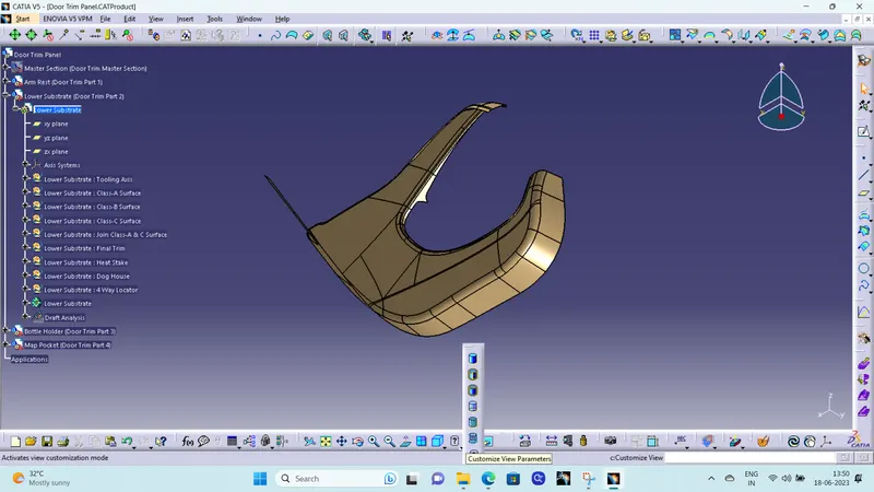

3. Then, ensure in Draft Analysis Box, Mode is swicted to Quick analysis mode, Color scale Display should be on, select the compass to define the direction.
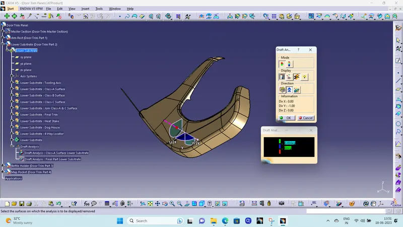
4. Drag the compass on the tooling axis for Draft Analysis then select the surafce or body to be draft analysed.
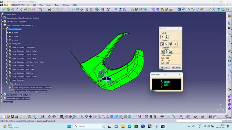
Note : Under Draft Analysis Color Display Dialog Box double click on the parameter tab and input the desired angle on which draft analysis to be perform.
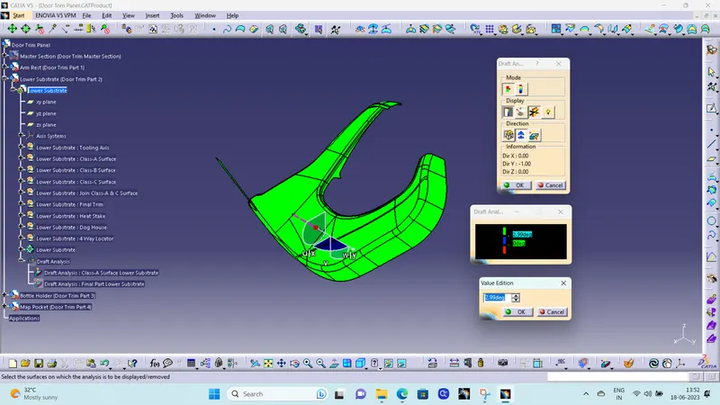
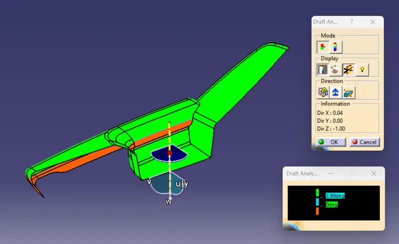
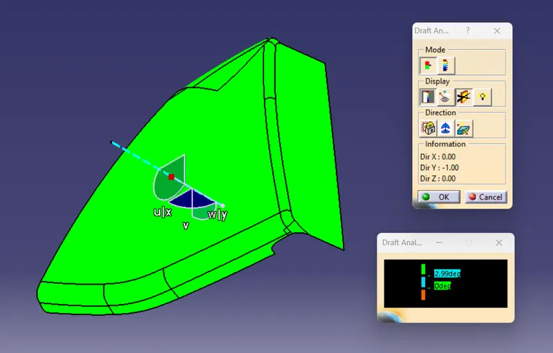
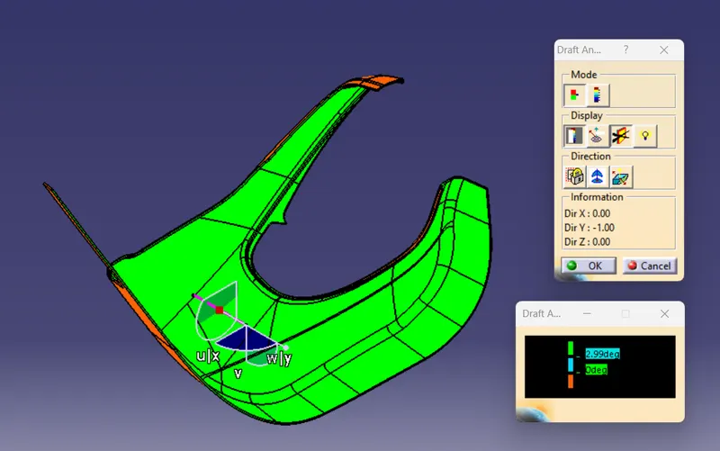
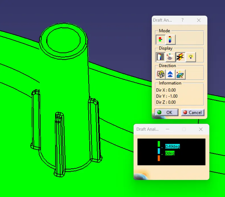
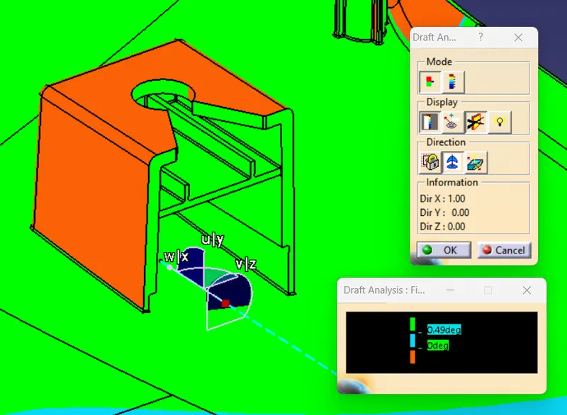
For Draft Analysis of Class-A Surface & Final Part : Draft Angle is taken as 2.99 Degree for Draft Analysis.
- Green : Angle is more than 2.99 Degree.
- Blue : Angle between 0 to 2.99 Degree.
- Red : Draft in Reverse Direction to selcted direction.
DRAFT ANALYSIS : CLASS A SURFACE
Draft Analysis : Arm Rest Class-A Surface
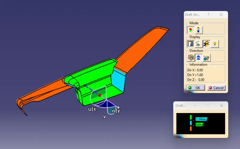
Draft Analysis : Bottle Holder Class-A Surface
Draft Analysis : Map Pocket Class-A Surface
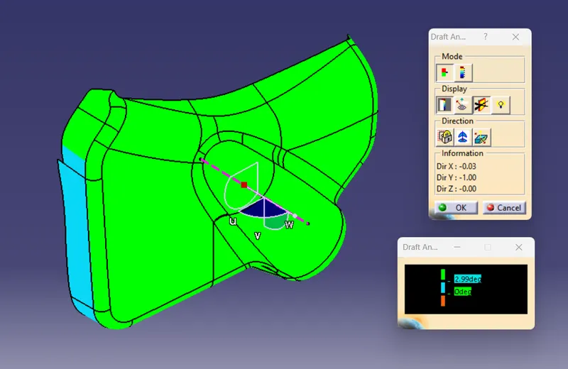
Draft Analysis : Lower Substrate Class-A Surface
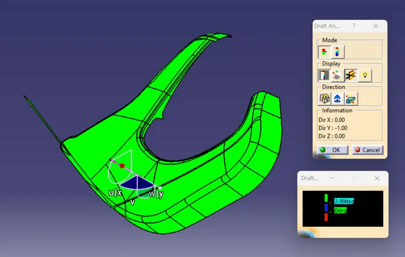
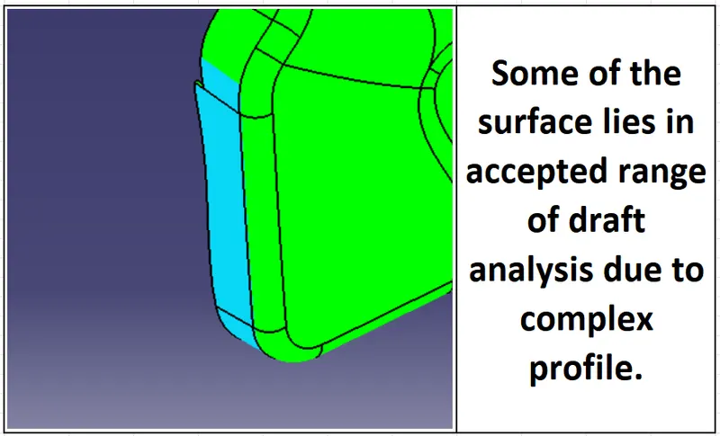
Note : Due to some complex surface some of the surface are in accepted range of draft analysis.
DRAFT ANALYSIS : FINAL BODY
Draft Analysis : Arm Rest Final Body
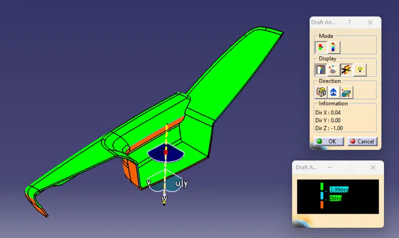
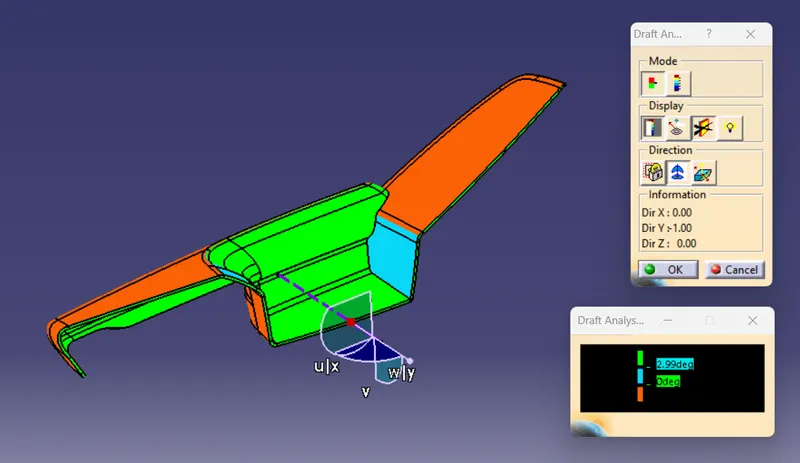
Draft Analysis : Bottle Holder Final Body
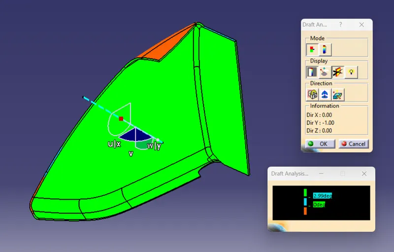
Draft Analysis : Map Pocket Final Body
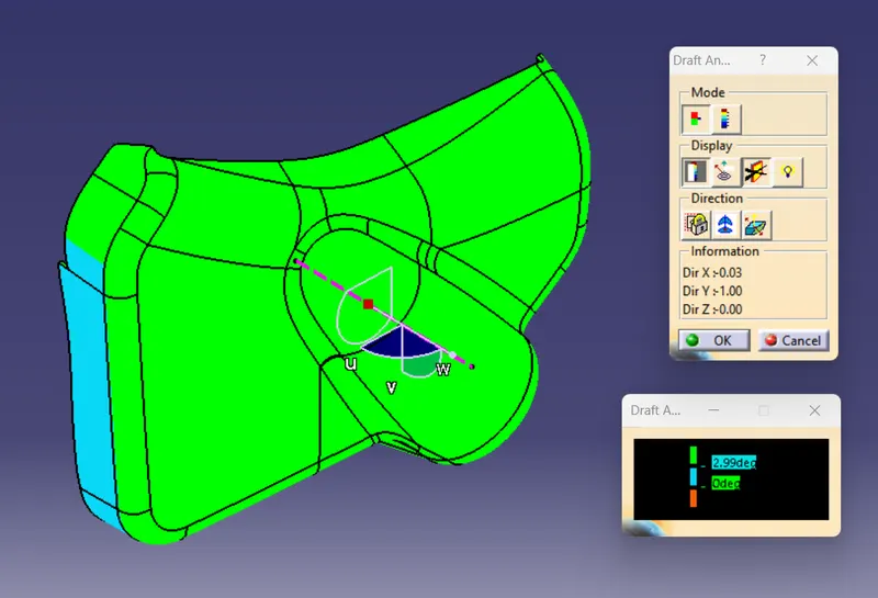
Draft Analysis : Lower Substrate Final Body
Note : Due to some complex surface some of the surface are in accepted range of draft analysis.
DRAFT ANALYSIS : CLASS C SURFACE
DOOR TRIM PANEL : ENGINEERING FEATURE DESIGN
4 WAY LOCATOR DESIGN
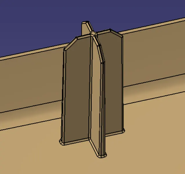
Steps for Locator Design :
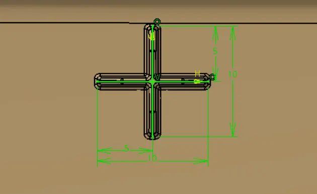
1. Sketch the Profile of 4 Way locator, sketch should be positioned sketch and iso-constrained.
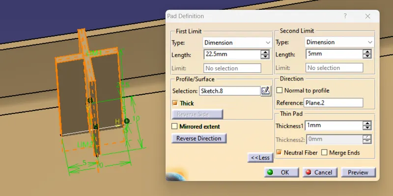
2. Pad the sketch as per design rule, dimension as per design rule as followed :
Locator Depth : Height of Locator = 22.5mm
Locator Thickness : 0.4*Thickness of Part = 0.4*2.5 = 1mm
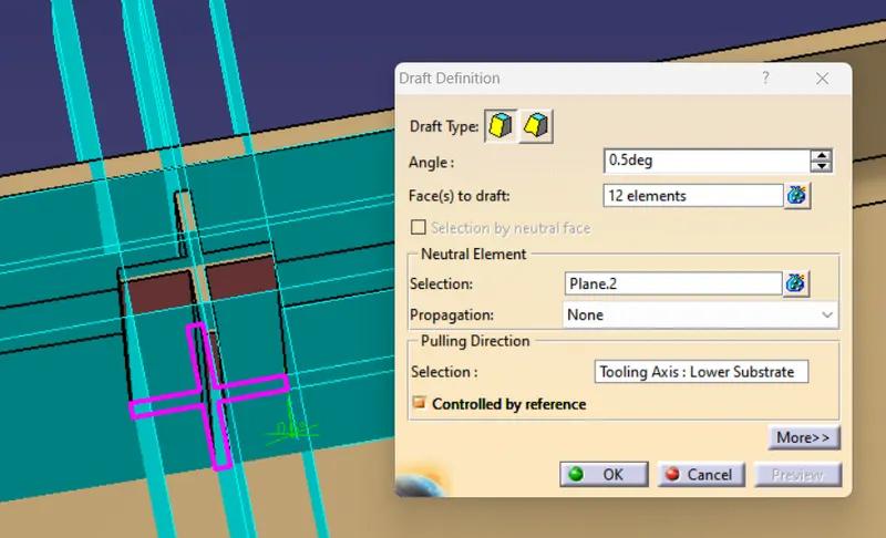
3. Draft the Pad locator in tooling direction, darft angle taken as 0.5degree as per design rule.
Draft Angle : 0.5 Degree
Pulling Direction : Tooling Axis
4. Chamfer the edges after drafting the face of locator.
Chamfer Length : 2mm
Chamfer Angle : 45 Degree
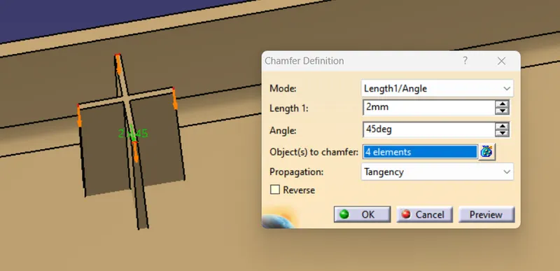
5. Fillets the edges of Locator faces after chamfering as per design standard.
Edge Fillet Radius : 0.25 mm
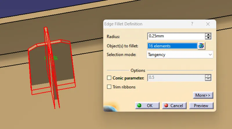
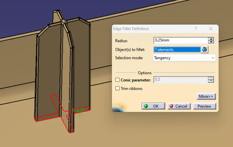
6. At the end, trim the locator with Door trim body and fillet the intersection of locator and door trim lower as per design standard.
Edge Fillet Radius : 0.25mm
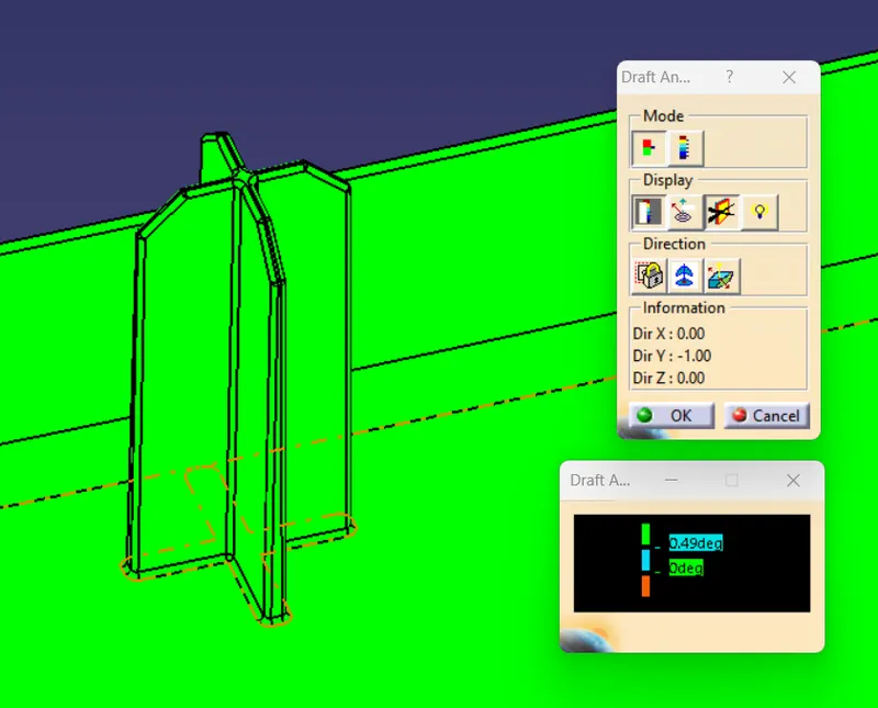
Draft Analysis : Locator
HEAT STAKE
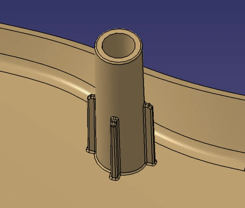
Steps for Heat Stake Design :
1. Sketch the Heat Stake Profile, SKetch two circle with difference of radius of 1.5mm as per design standard.
Heat Stake Thickness : 1.5mm
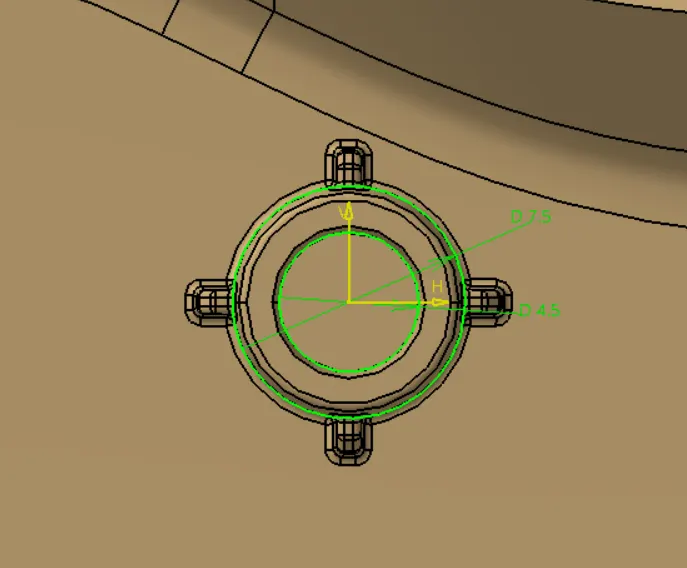
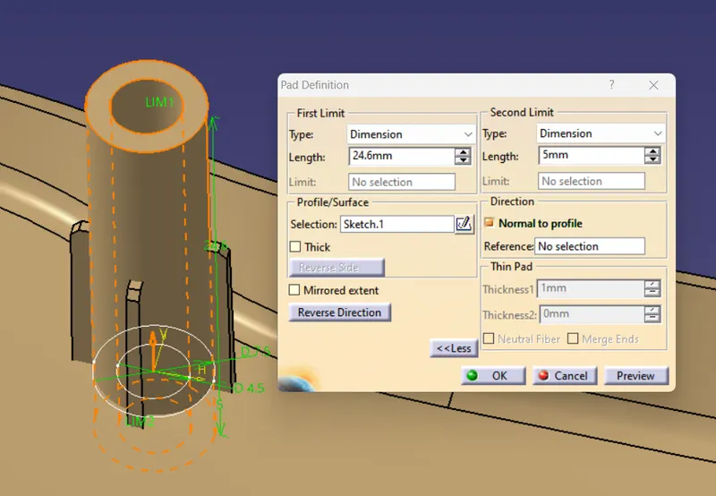
2. Pad the sketch of heat stake upto required height from surface, maximum upto 35mm. For more than this use dog house for Heat Stake attachement.
Heat Stake Depth : 24.6mm
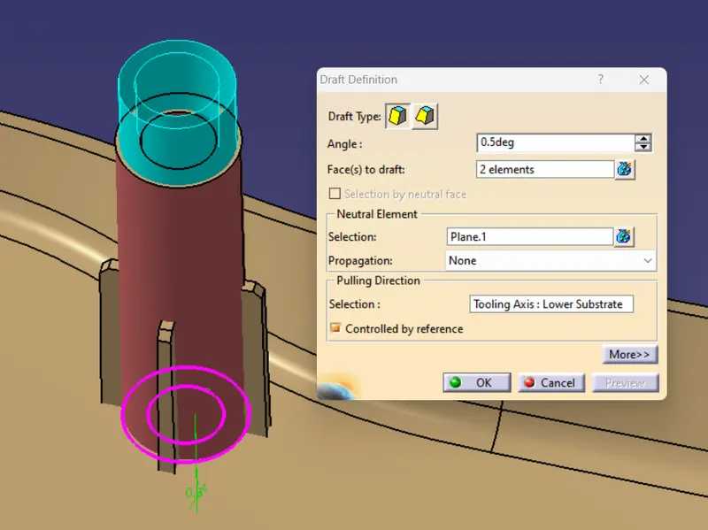
3. Draft both Inner and Outer face of Heat stake pad as per design rule.
Draft Angle : 0.5 Degree
4. Edge fillet the Heat stake pad after drafting as per design standard.
Edge Fillet Radius : 0.25mm
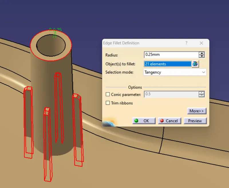
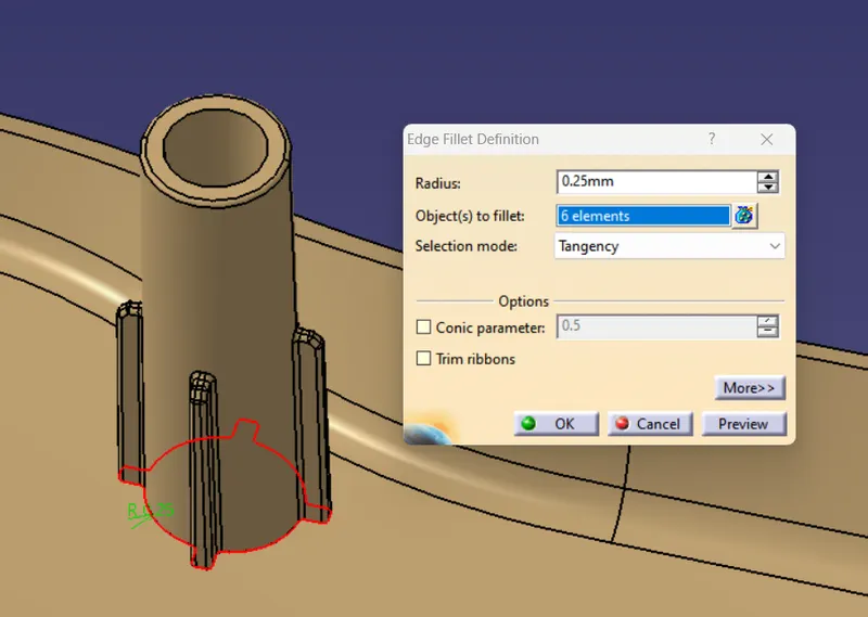
5. At the end, trim the heat stake with door trim and then edge fillet the intersection of heat stake and door trim lower.
Edge Fillet Radius : 0.25mm
Draft Analysis : Heat Stake
DOG HOUSE
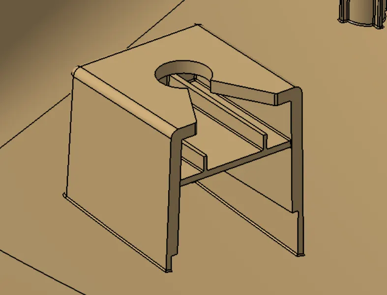
Steps for Dog House Design :
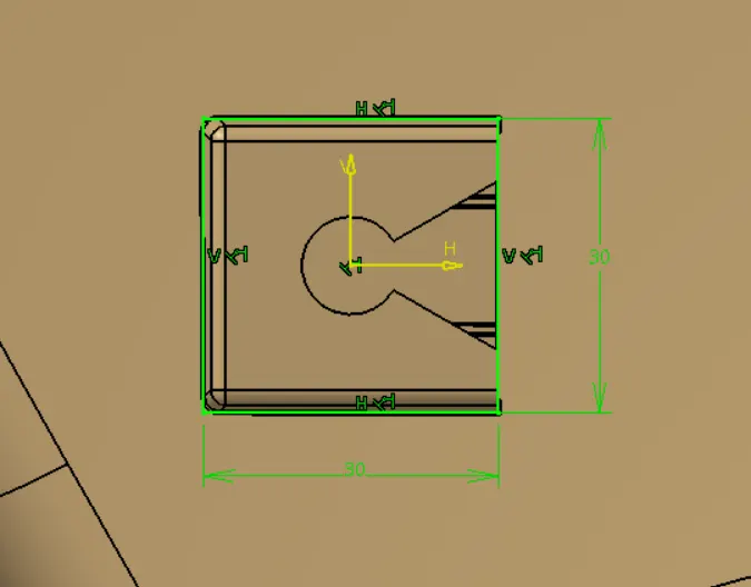
1. Create a sketch for dog house, sketch should be iso-contrained.
Dog House Dimension : 30*30 mm.
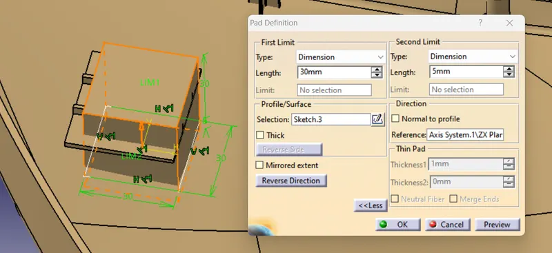
2. Pad the sketch to required length.
Dog House Height : 30 mm
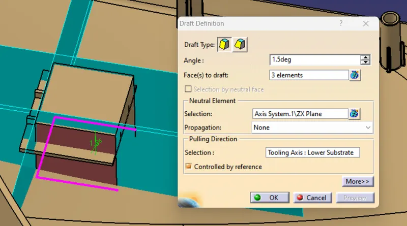
3. Draft the side faces of Pad in main tooling direction expect the top and Front face of side core tooling direction.
Draft Angle : 1.5 Degree
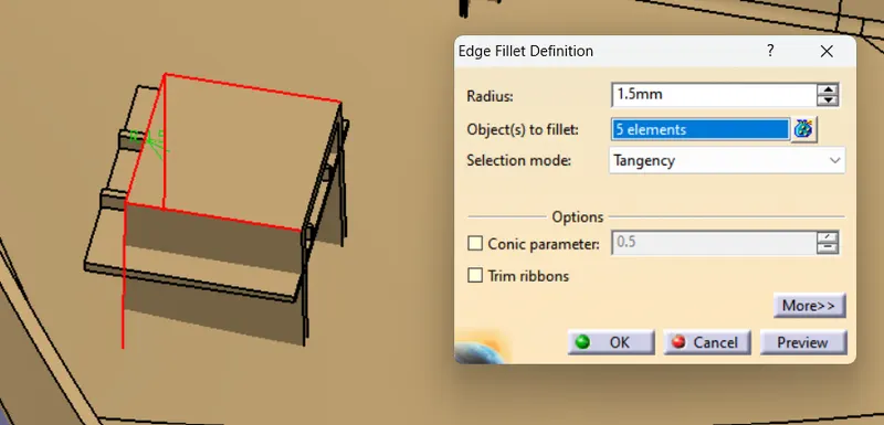
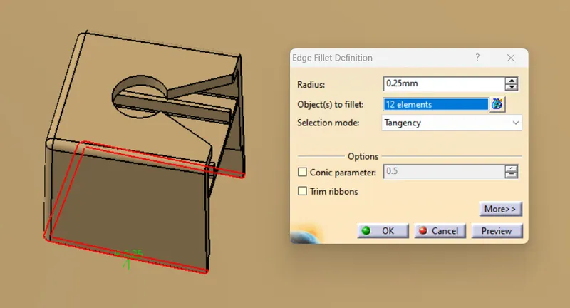
4. Fillet the edge of Pad after providing draft.
Edge Fillet Radius : 1.5 mm
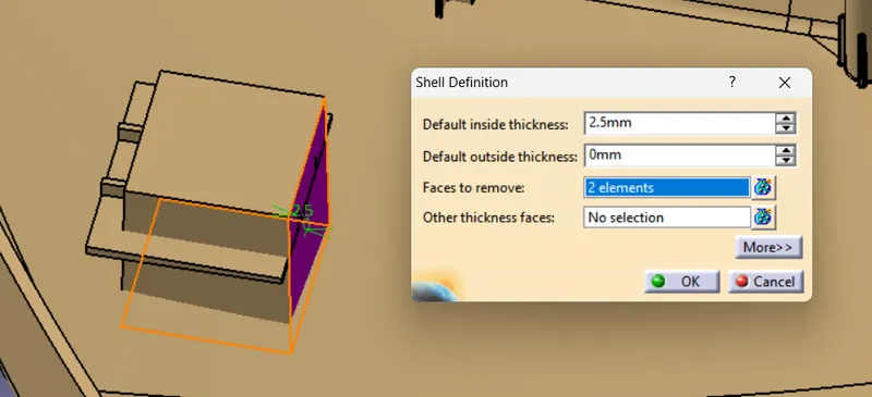
5. Create a Shell in Pad after draft and edge fillet, having same wall thickness as the thickness of part.
Shell Thickness : 2.5 mm
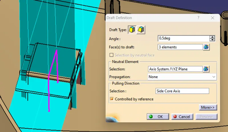
6. Draft the inner face of Pad in side core axis direction after shell creation.
Draft Angle : 0.5 Degree
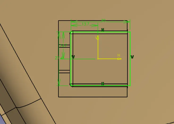
7. Create the sketch for intersection of dog house at surface of part.
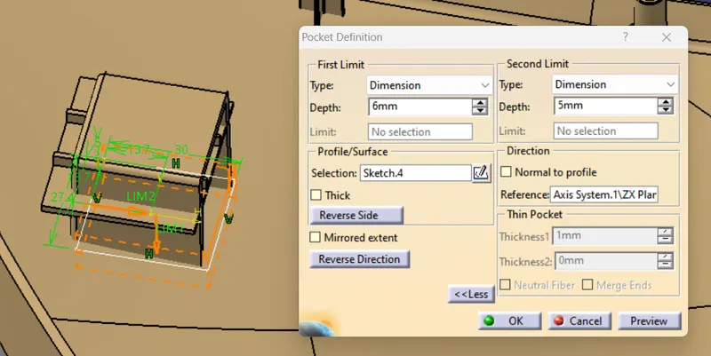
8. Pocket the sketch with length in range of 3-6mm from surafce as per deisgn rule.
Pocket Depth : 6 mm
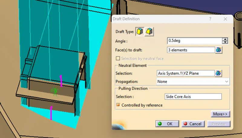
9. Draft the pocket face in side core tooling direction.
Draft Angle : 0.5 Degree
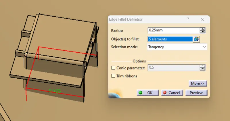
10. Edge fillet the pocket edges.
Edge Fillet Radius : 0.25 mm
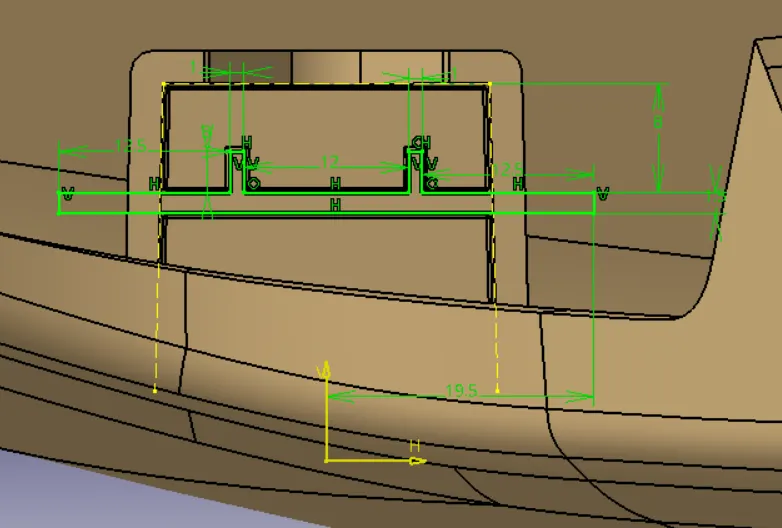
11. Sketch the ribs as given below.
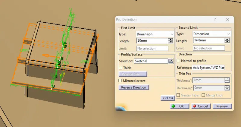
12. Pad the sketch of ribs.
Pad Length : 20 mm
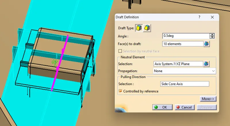
13. After pad, Draft the face of ribs and then trim the ribs out with dog house.
Draft Angle : 0.5 mm
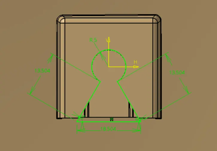
14. Create the sketch of hole on dog house for the assembly of push pin clip.
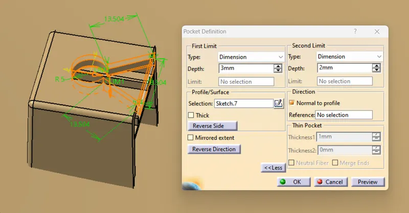
15. Poket the hole in dog house for push pin clip assembly.
Hole Depth : 3 mm
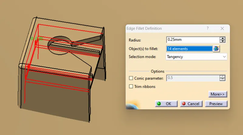
16. Edge fillet the edges of dog house and ribs.
Edge Fillet Radius : 0.25 mm
17. Edge fillet the dog house intersection after trimming out the dog house with body.
Edge Fillet Radius : 0.25 mm
Draft Analysis : Dog House
Outer Face of Dog House
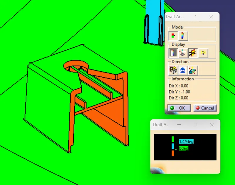
Inner Face of Dog House
FLANGE
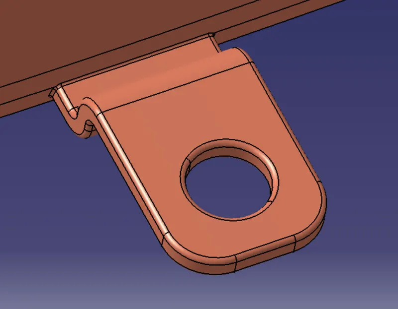
Steps for Flange Design:
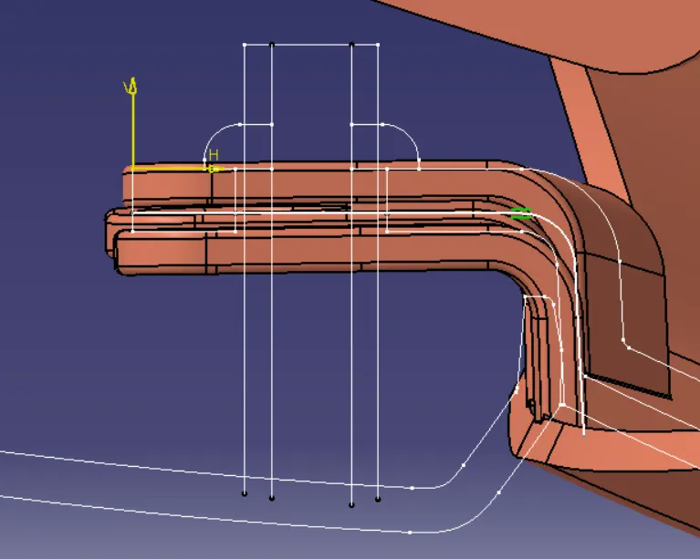
1. Create the sketch of flange after extracting the boundary of flange from master section.
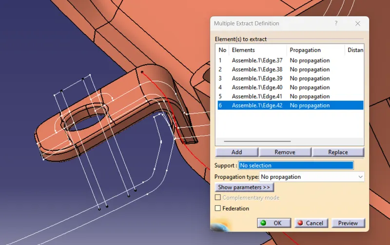
2. Extract the boundary of part.
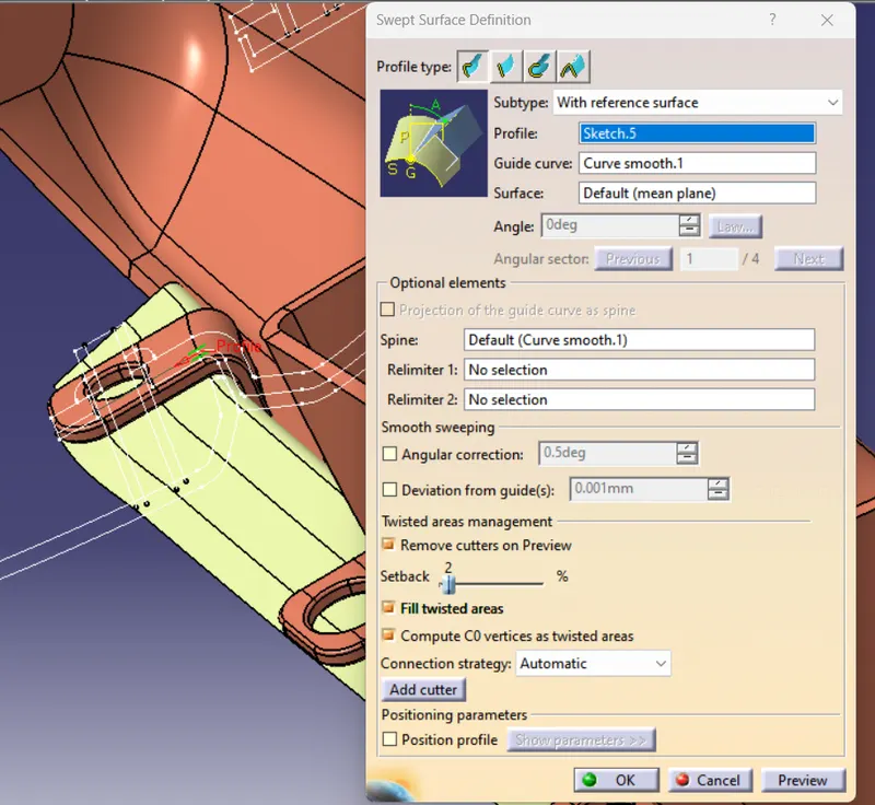
3. Sweep the sketch of flange with extracted boundary as guide curve in reference to the surface.
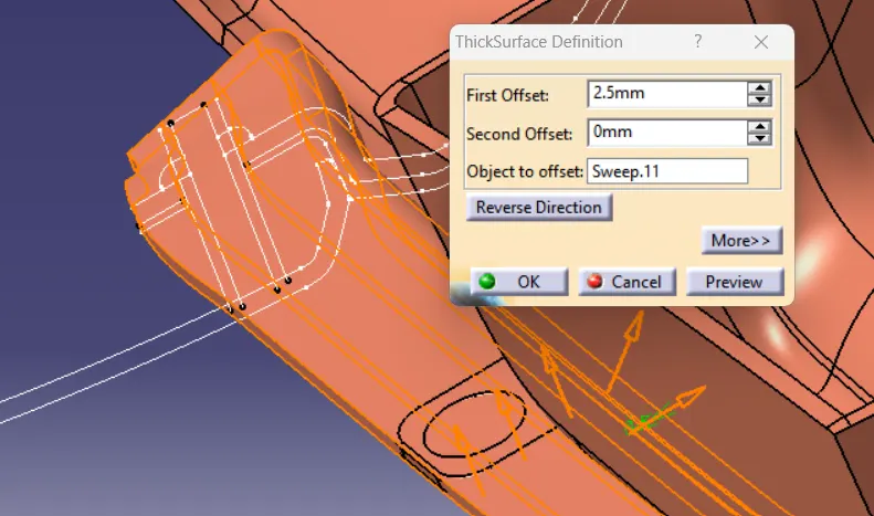
4. Thicken the sweep surface as per thickness of flange given in master section.
Flange Thickness : 2.5 mm
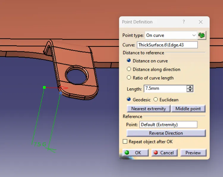
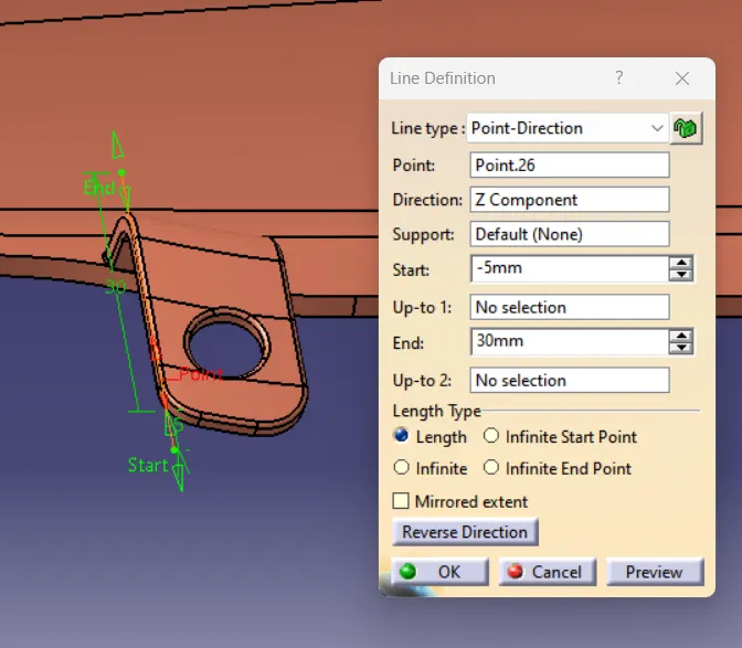
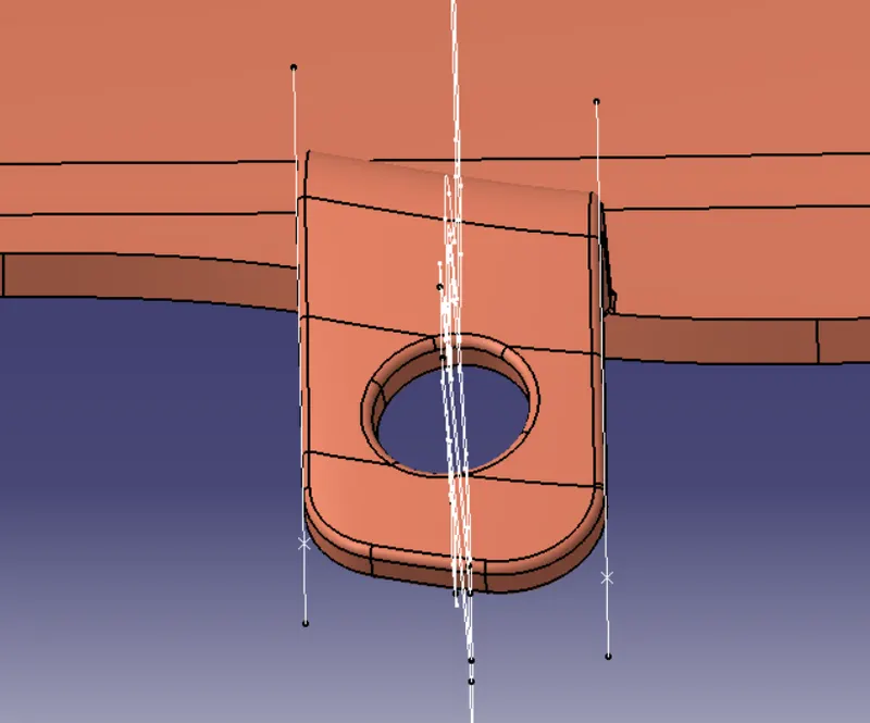
5. Create the normal line to the curve of the thicken surface from the point created on the curve of sweep surface.
Creating a point on curve of thicken surface.
Creating a line normal to the curve through reference point.
6. Extract the created line to split out the flange.
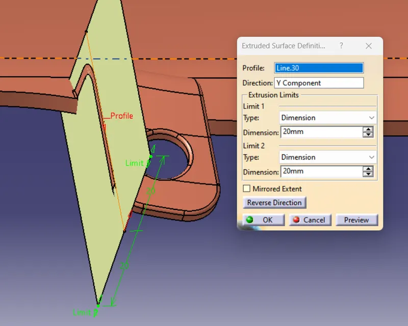
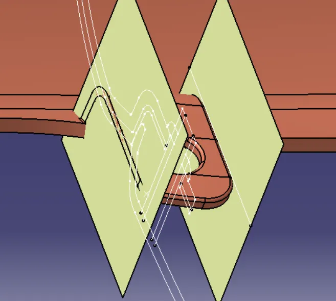
7. Split out the flange with extracted surface.
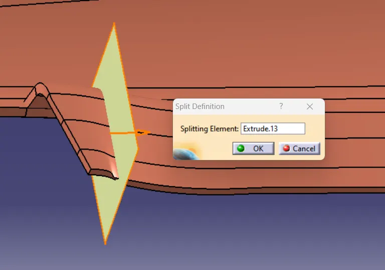
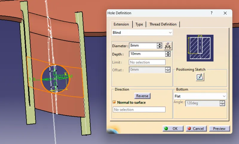
8. Create a hole on the surface of flange such that it pass through heat stake.
Diameter : 8 mm (with 0.5 clearence to the wall of heat stake).
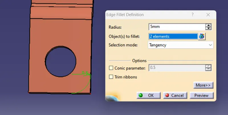
9. Fillet the cornor of flange.
Edge Fillet Radius : 5 mm
10. Fillet the both faces of flange after creating a hole.
Edge Fillet Radius : 0.5 mm
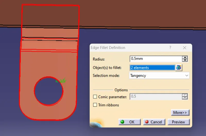
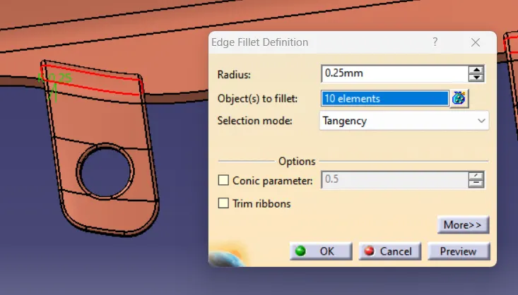
11. Fillet the intersection of flange after trim out the flange with base body.
Edge Fillet radius : 0.25mm
MASTER SECTION VALIDATION
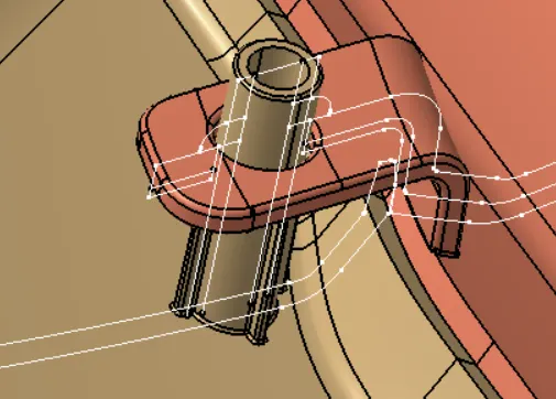
1. Master Section between Arm Rest and Lower Substrate.
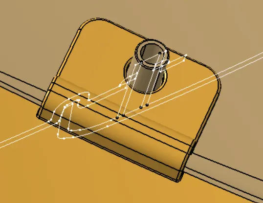
2. Master Section between Lower Substrate and Bottle Holder.
DOOR TRIM PANEL ASSEMBLY
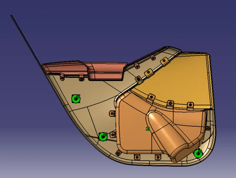
Component of Door Trim Panel:
Arm Rest
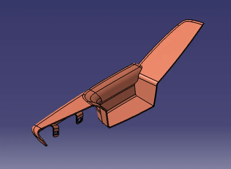
Bottle Holder
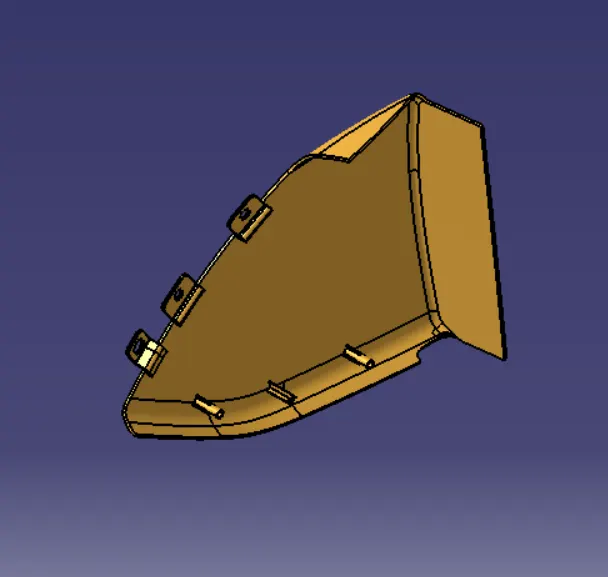
Lower Substrate
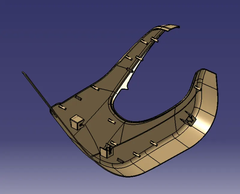
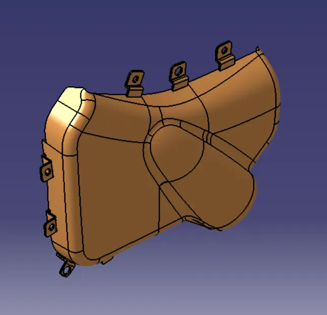
Map Pocket
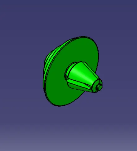
Push Pin Clip
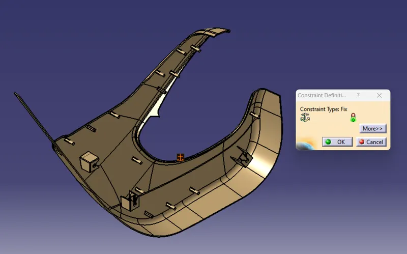
Steps for Assembly of Push Pin Clip:
1. Fixed the lower substrate with Fixed Constraint.
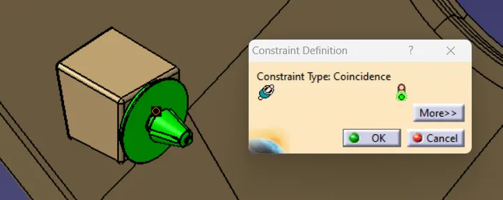
2. Coincide the axis of Push Pin Clip with Dog House Hole Axis using Coincidence constraint.
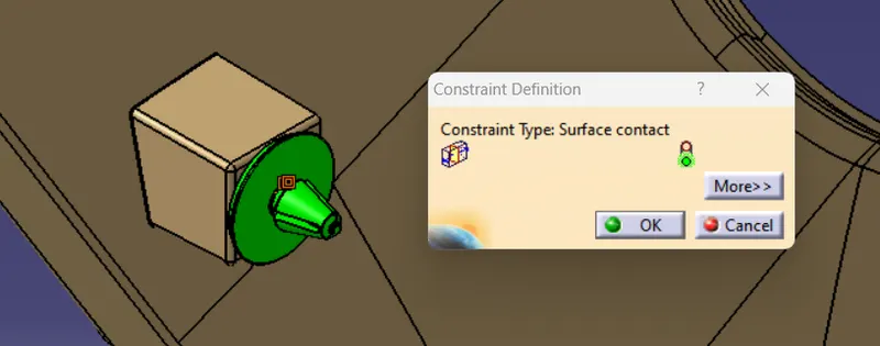
3. Contact the bottom surface of push pin clip with top surface of dog house using Surface Contact.
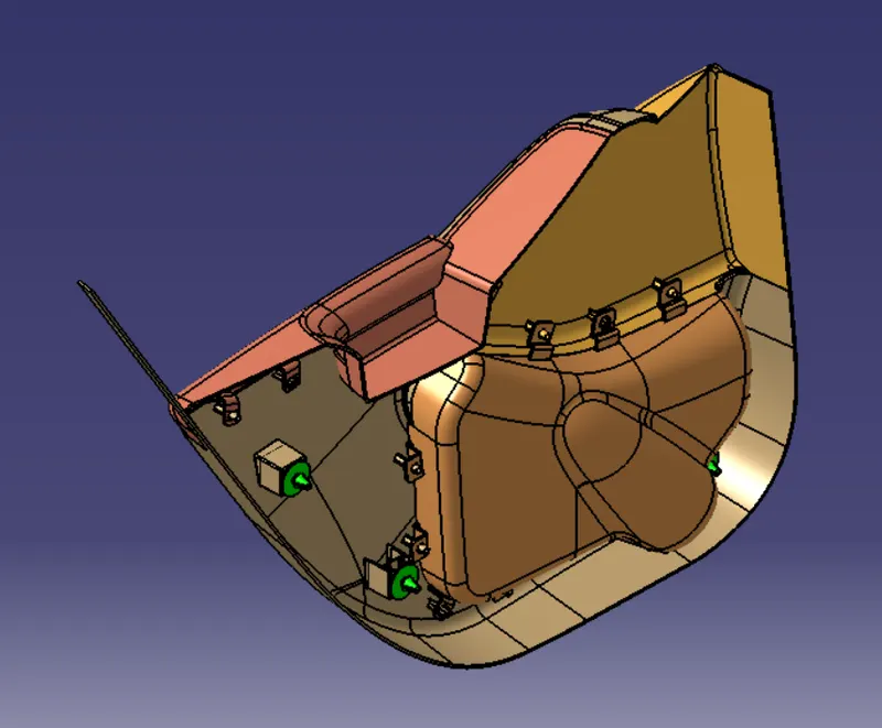
DOOR TRIM PANEL
Isometric View
Top View
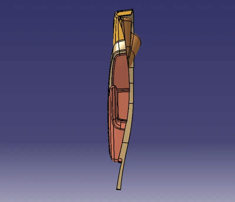
Side View
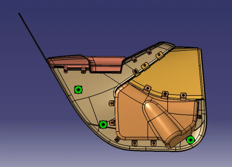
Front View