Week 12- Final project
Your Answers
Dear sir,
Title:- Final Trim Project in CATIA V5
Tools:- 1) Input class A features for Bottle Holder, Map pocket, Lower Substrate, Arm Rest
2) Thickness of each part is 2.5 mm
3) Master Section is given For Interlocking between all individual Parts to form Assembly
4) Push pin Part for doghouse Assembly
4) CAD Software (Catia V5)
Procedure:- 1) Create a Tree Flow chart for making a Complete solid Part for Each Body
A) Lower substrate
I) Get Input as Class A surface
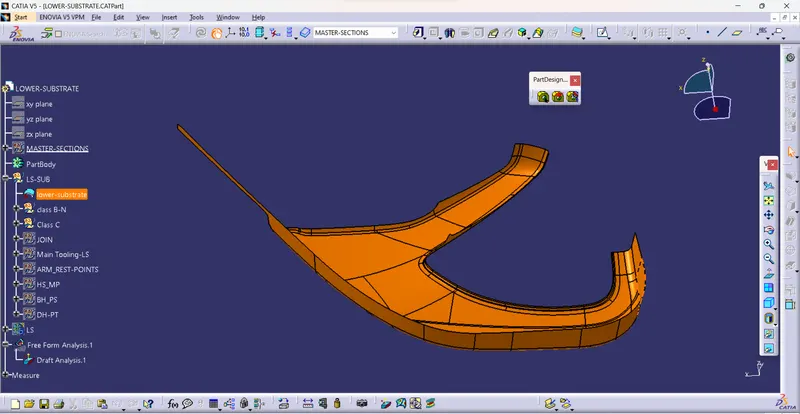
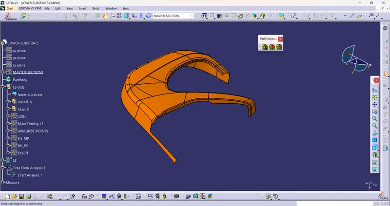
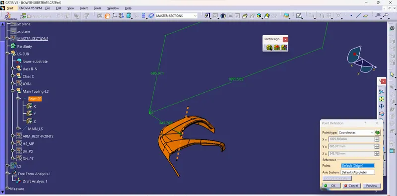
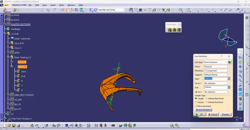
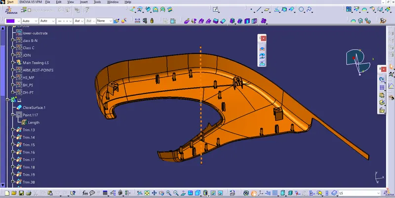
II) Create the Main tooling axis By using the appropriate Method
Note:- To create the Tooling axis We have to check all component's Tooling axis, as all Other parts like Bottle Holder, Armrest, and Map Pocket are Going To assemble with the Lower substrate. To prevent misalignment and improper connection, we must maintain a parallel Tooling axis, So they will Assemble together Very well.
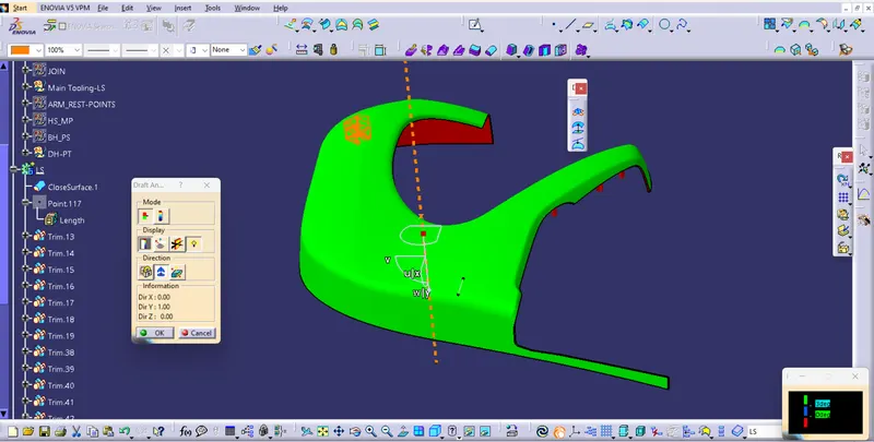
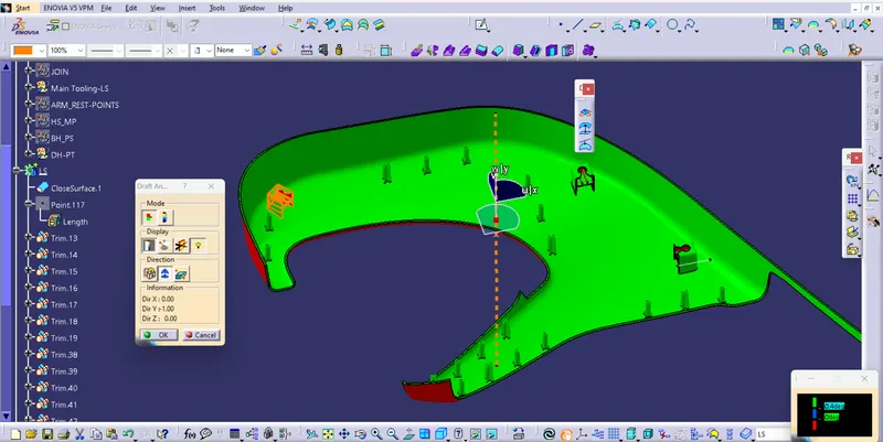
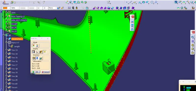
III) Perform Draft analysis on Class A surface
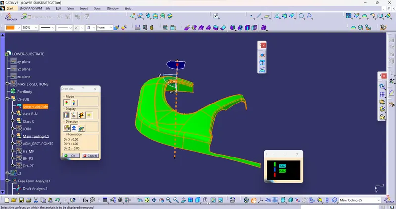
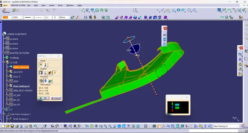
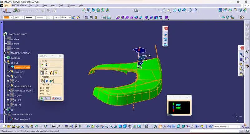
IV) Create a Class B surface
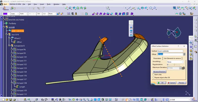
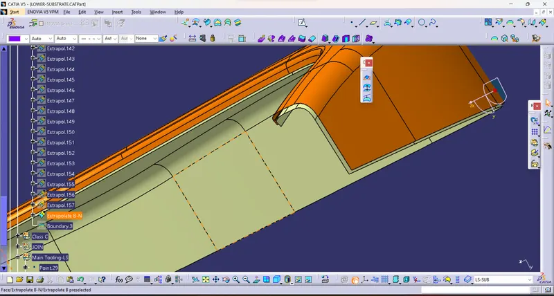
V) Create a Class C surface
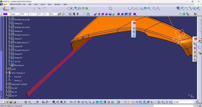
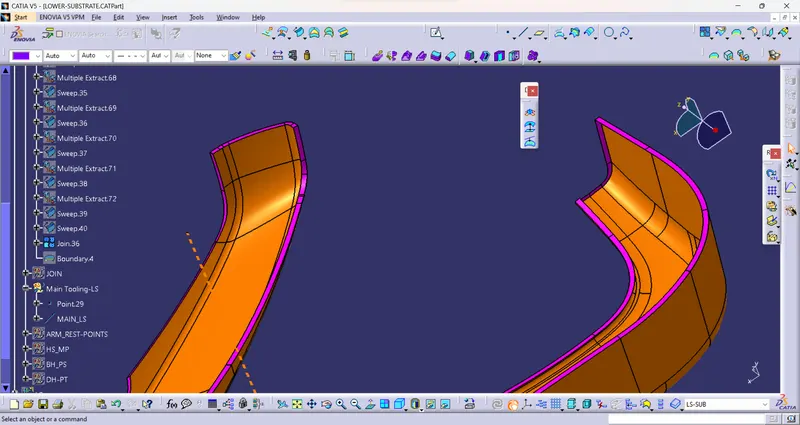
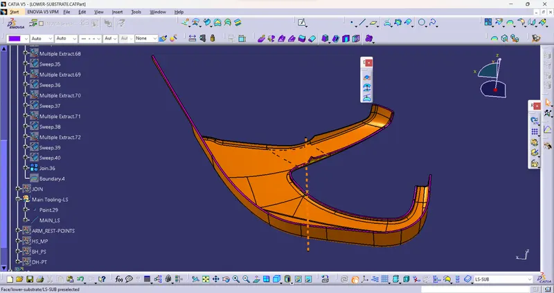
VI) Close all A, B, and C surfaces and make a Close Surface Feature
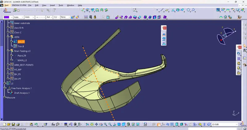
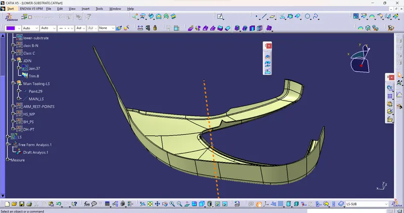
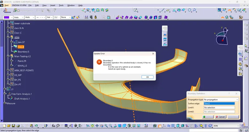
VII) Create solid Feature From Close surfaces
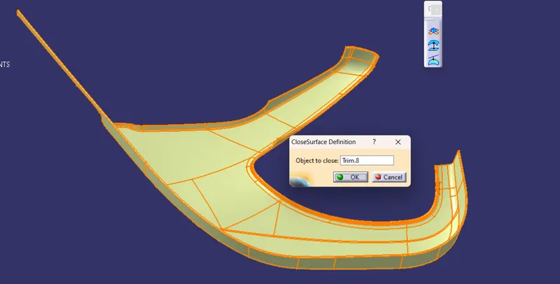
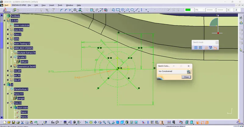
VIII) Create Heat Stakes and Locator Features
a) Base Sketch
a) choose or create a Plane where points Located
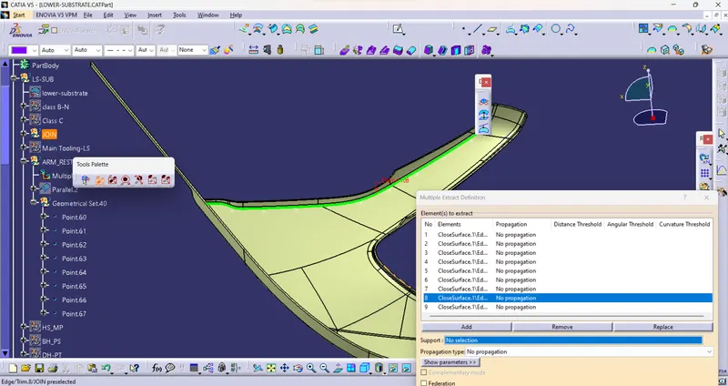
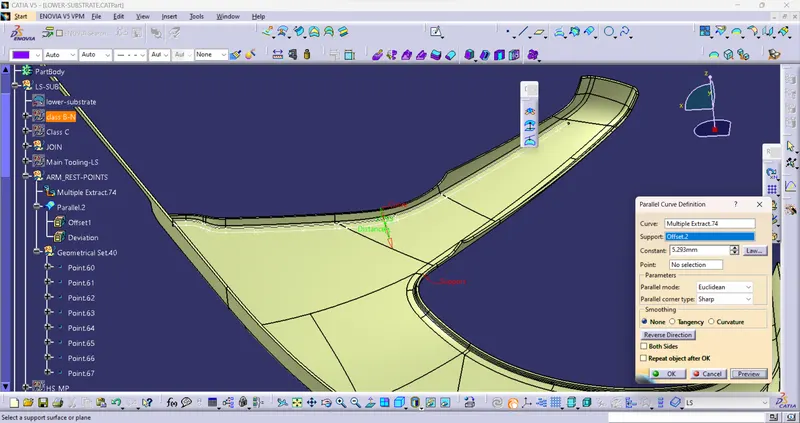
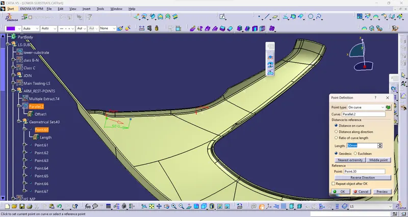
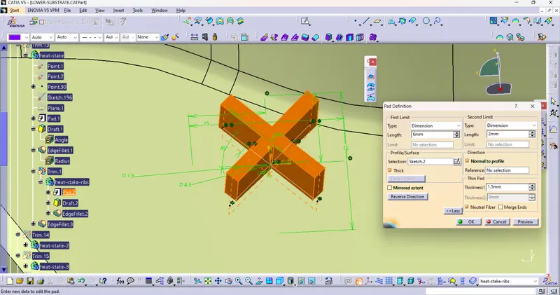
b) Create a Base Sketch For Heat stakes and locator and use the PAD command Draft with the central tooling axis
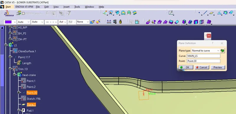
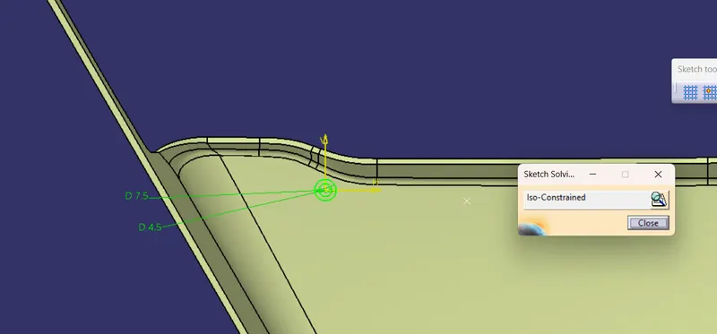
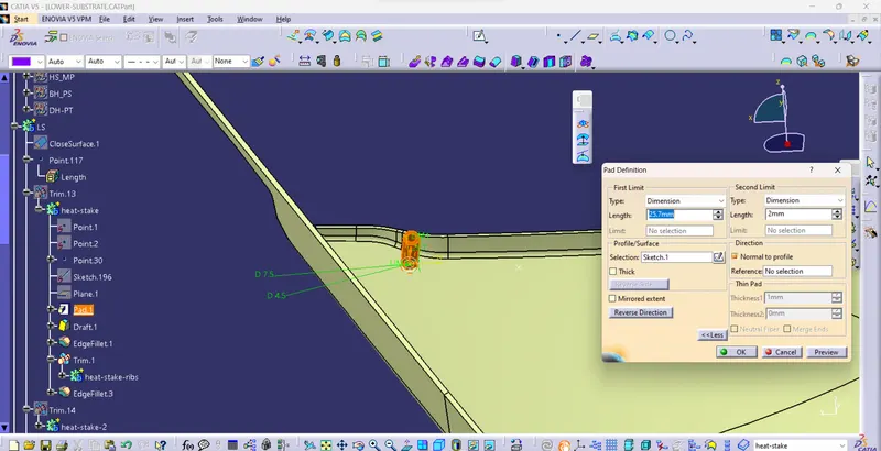
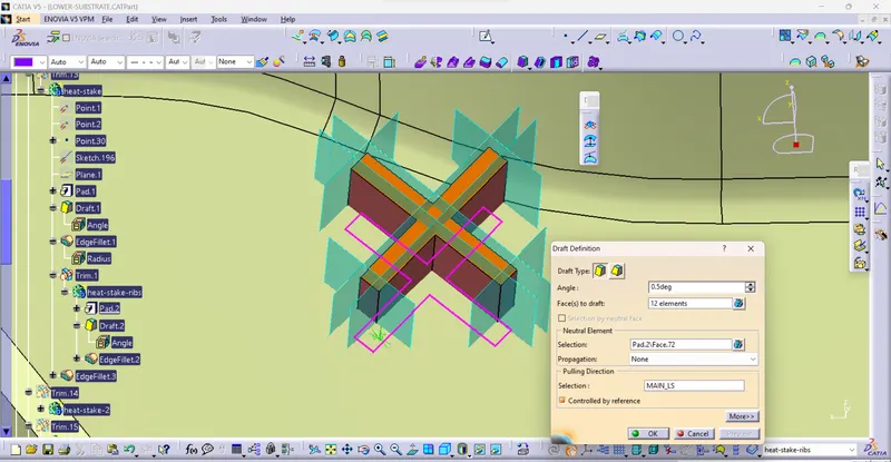
c) Perform Draft Operation if required
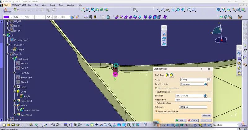
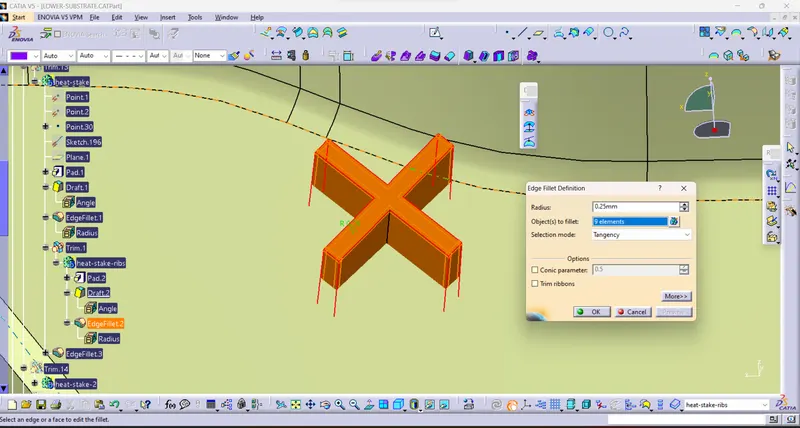
d) Perform Champher and Fillet Operations
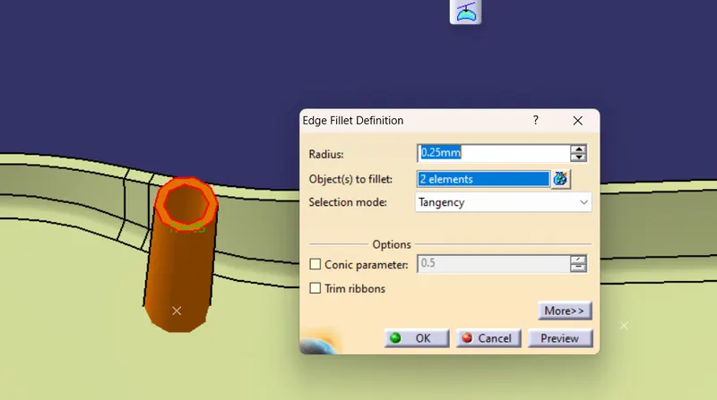
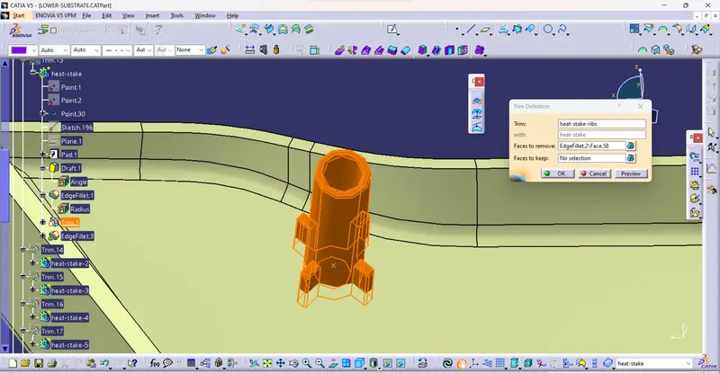
e) Create Ribs and trim then Perform Trim operations to create one single solid body
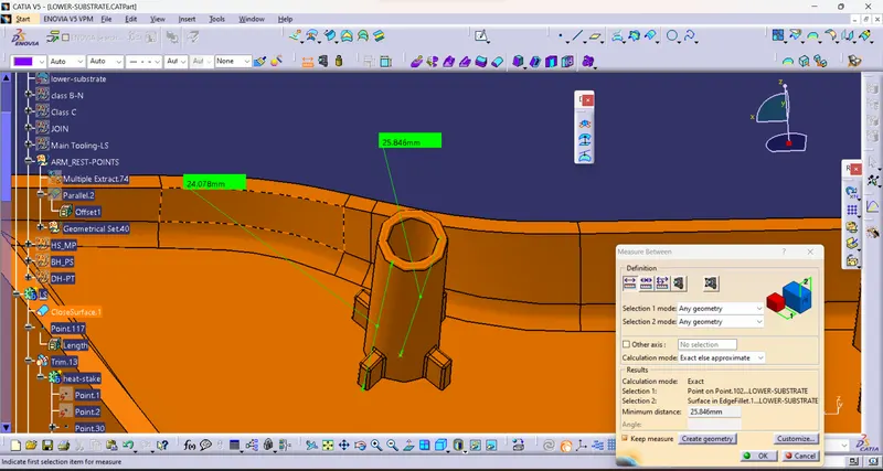
f) Check the Height of heat skates and locators From the base face -Class B
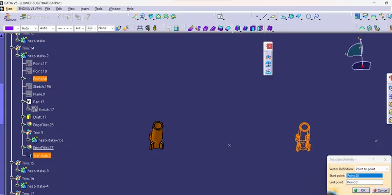
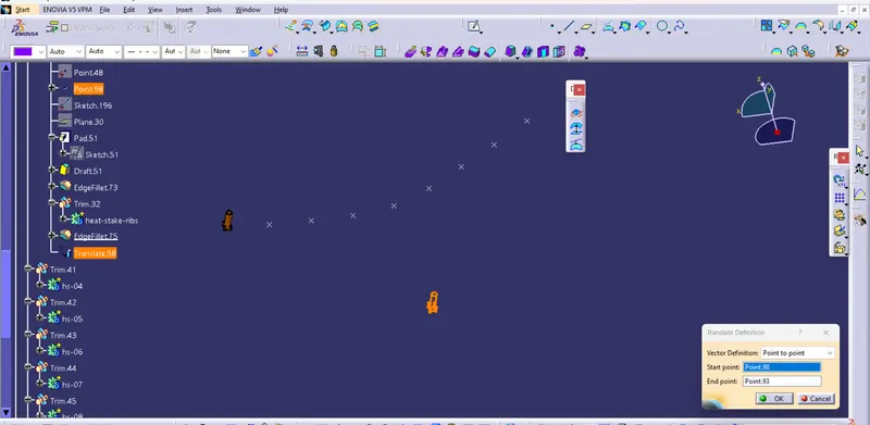
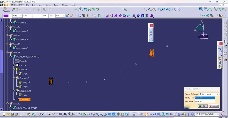
b) Translate Heat stakes to specified Points
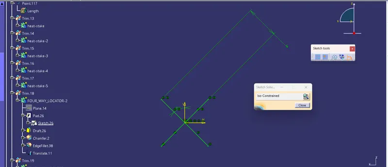
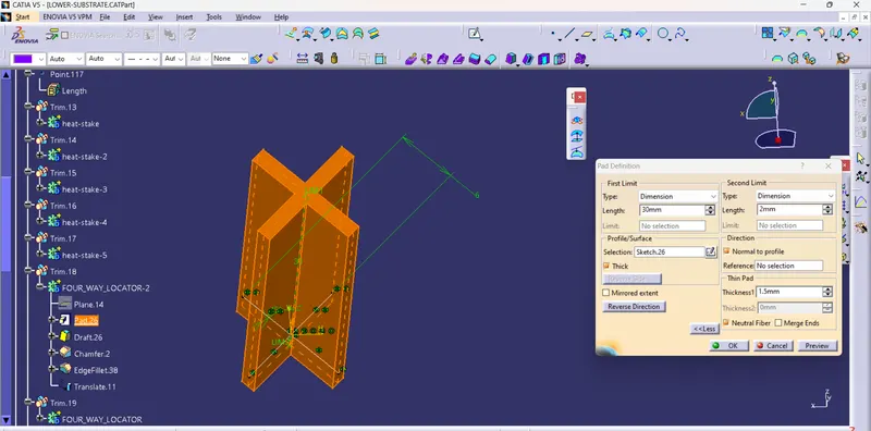
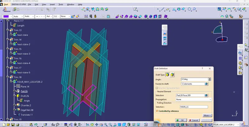
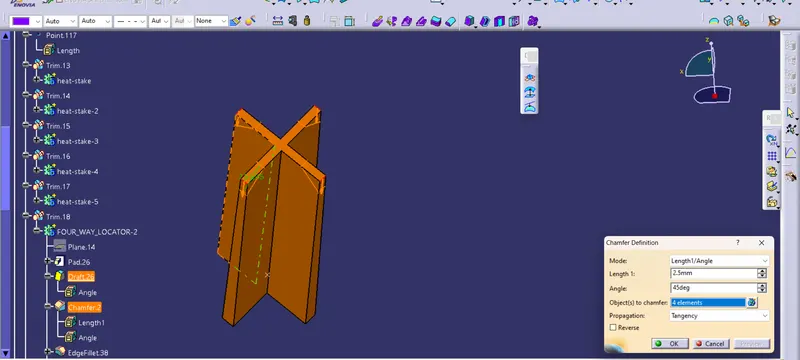
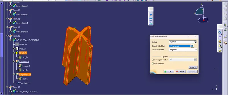
C) Create 4Way Locators- Sketch, Extrude, Draft, Fillet then Mearge to Solid Body
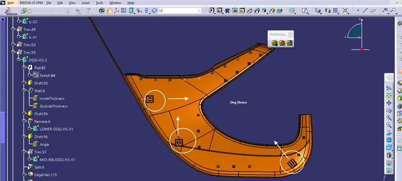
C) Create a dog house
i) Select Plane and Point Create Base Sketch for Dog house
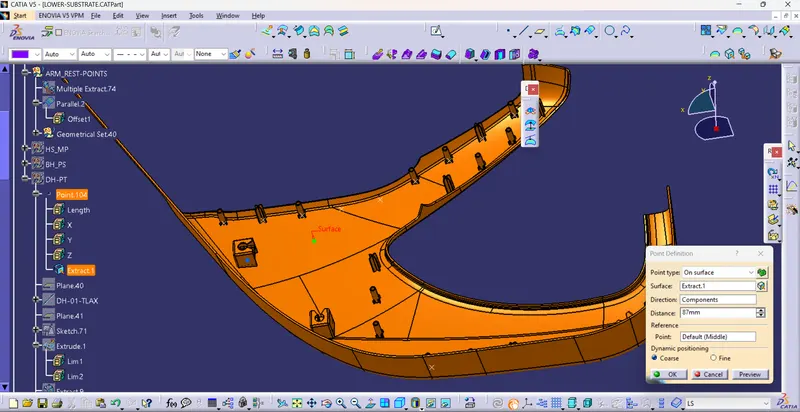
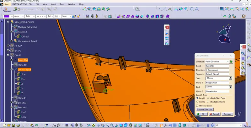
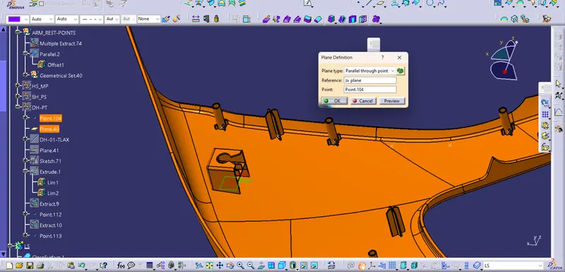
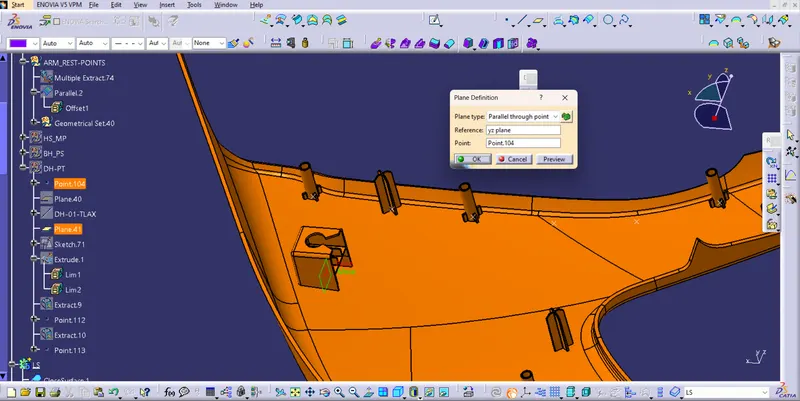
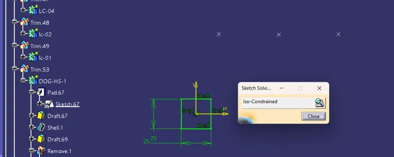
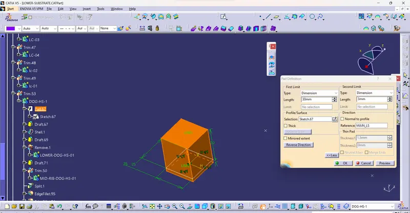
ii) Use Pad Command and Then draft as per angle
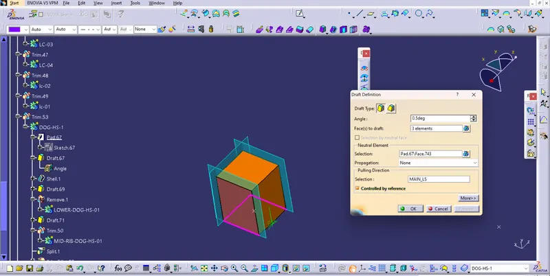
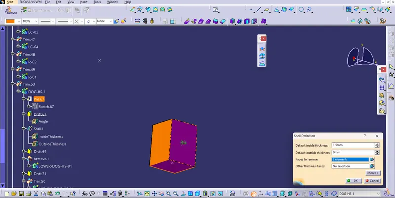
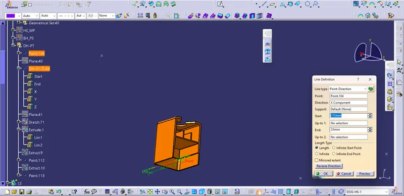
iii) Use the shell Command and then Create a Tooling axis for Core
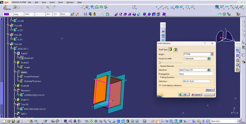
iv) Create Bottom Trim To Maintain Surface Flow and avoid any Plastic Damage
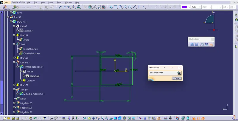
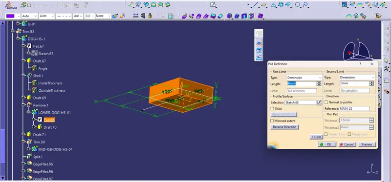
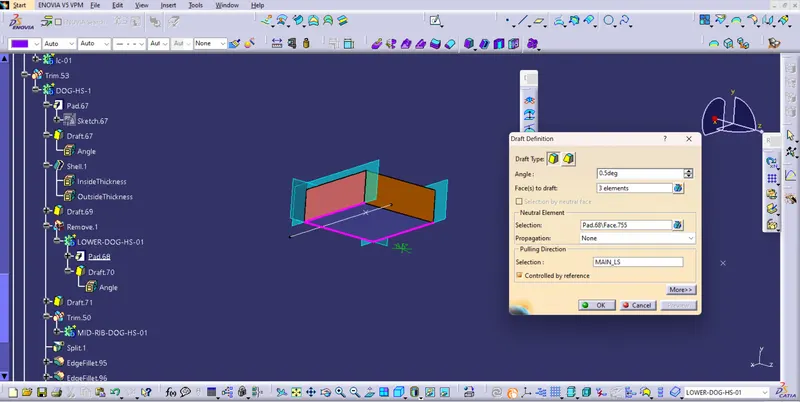
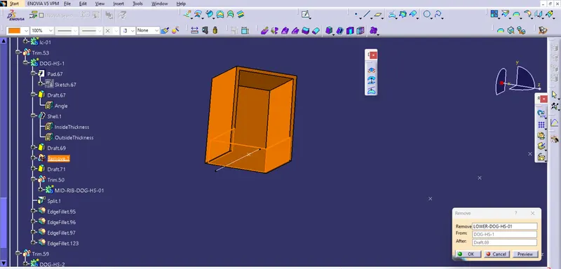
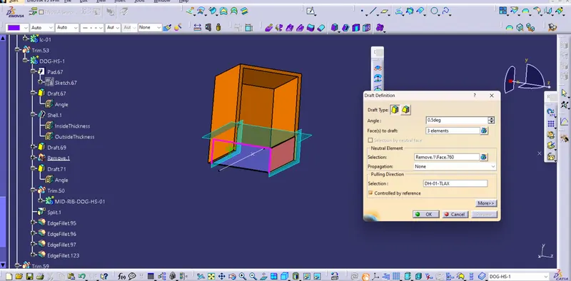
v) Create Ribs for Pushpin support which help to get the slide and fix into assembly
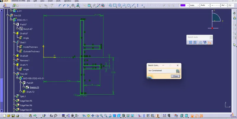
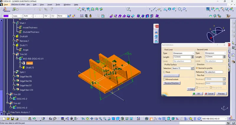
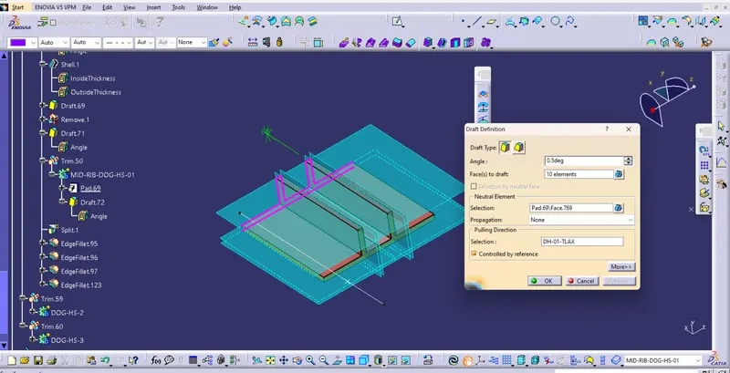
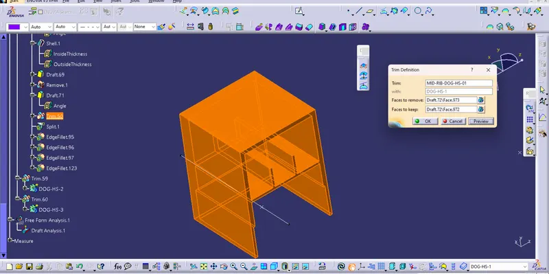
vi) Split the top Mounting hole and apply the required fillets
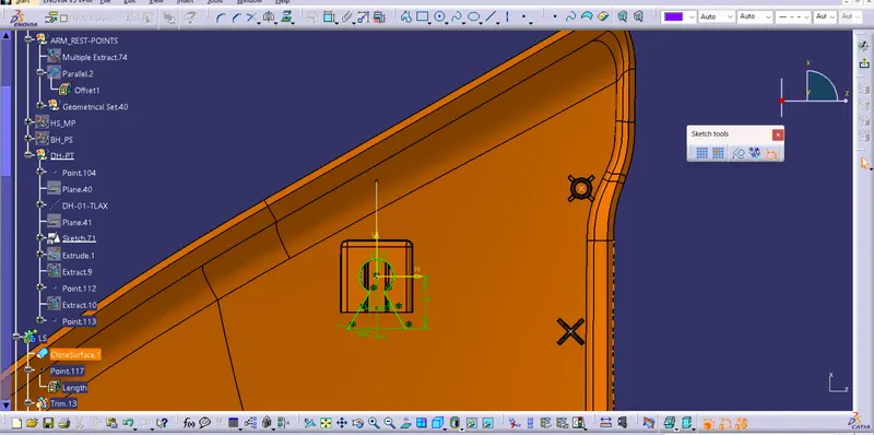
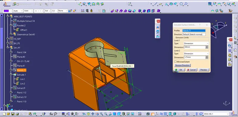
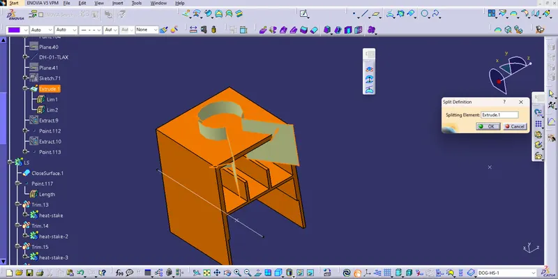
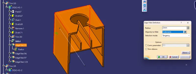
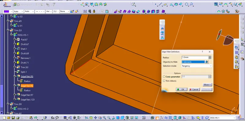
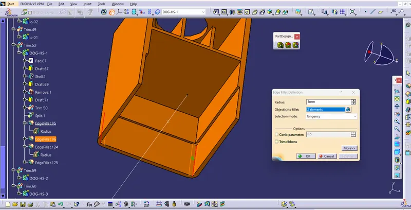
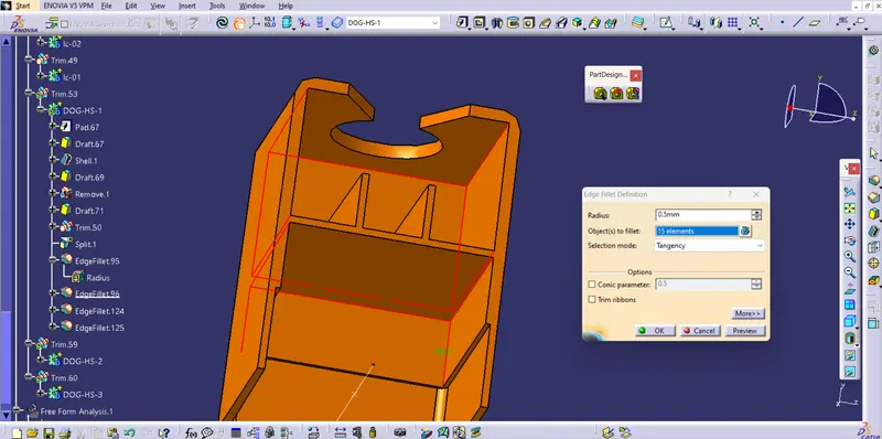
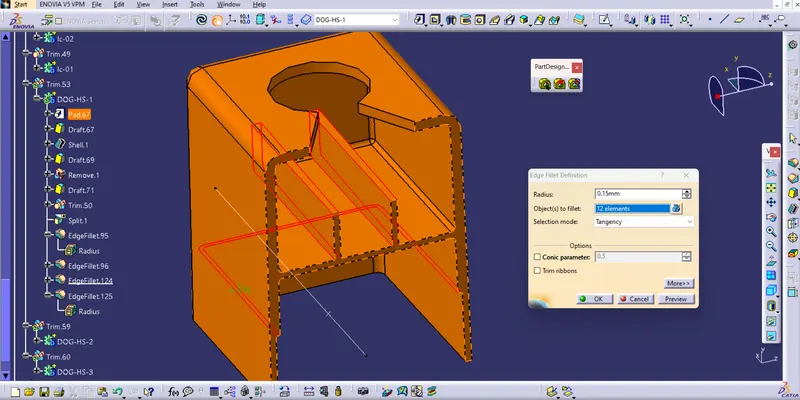
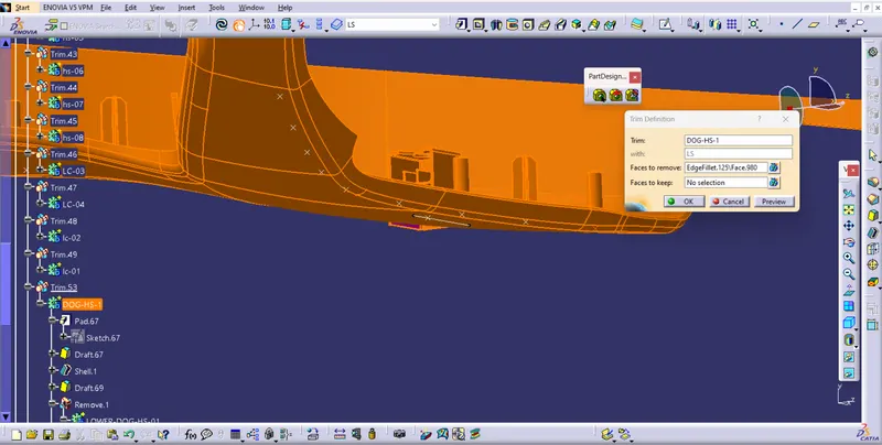
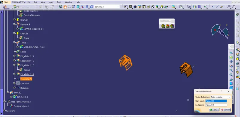
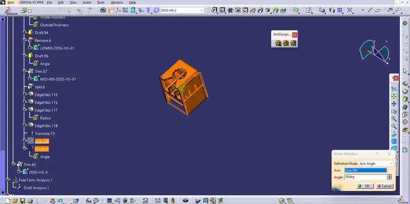
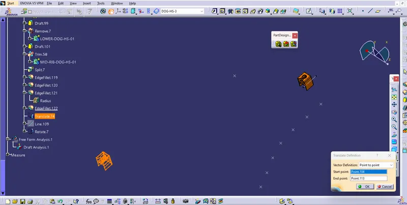
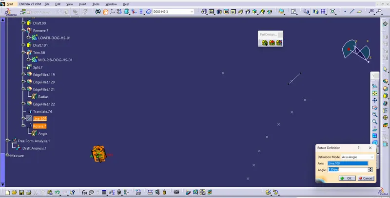
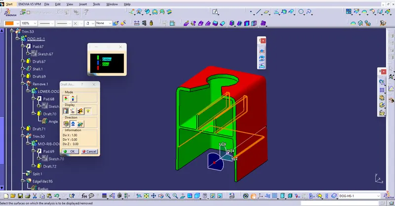
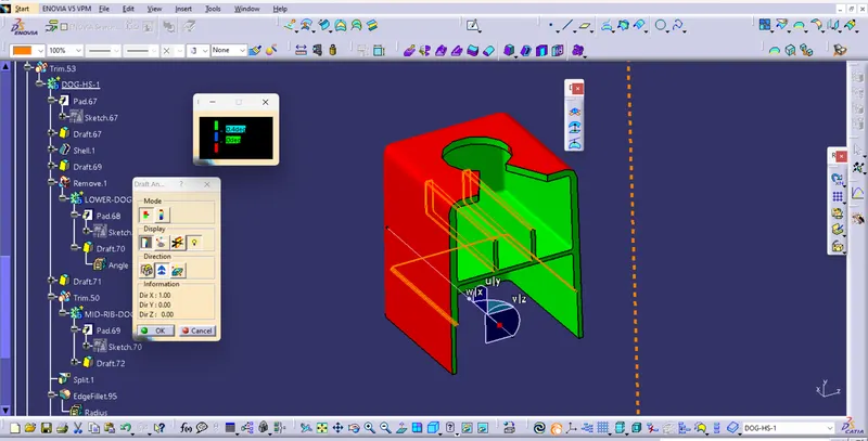
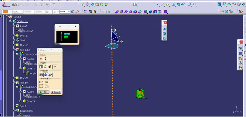
vii) Perform Draft analysis for the Dog house as per core Direction and main tooling axis
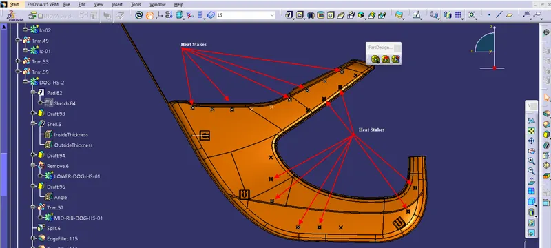
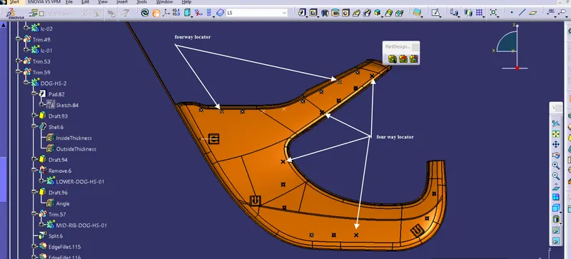
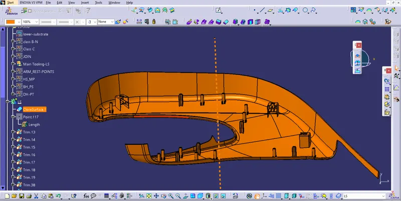
B) Map Pocket
I) Get Input as Class A surface
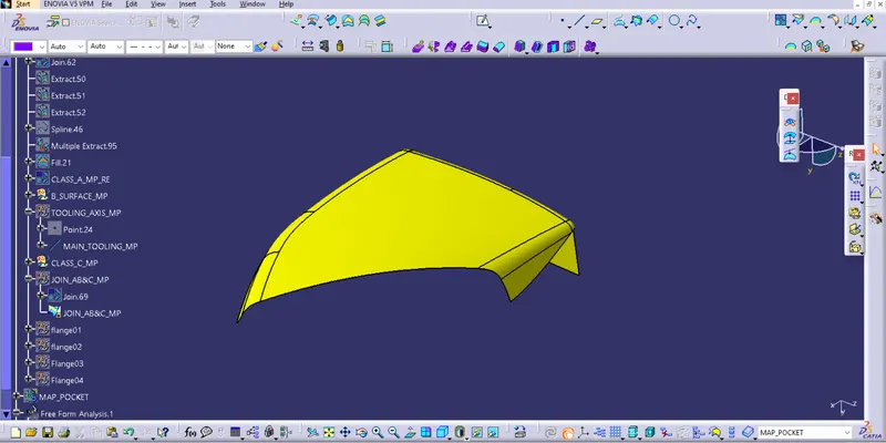
II) Create the Main tooling axis By using the appropriate Method
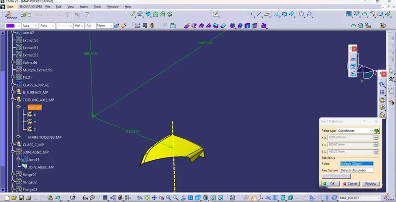
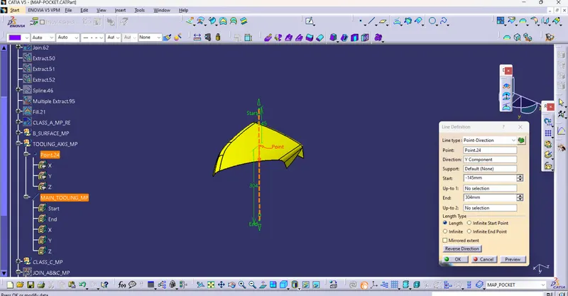
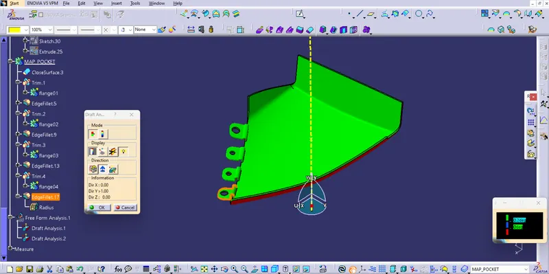
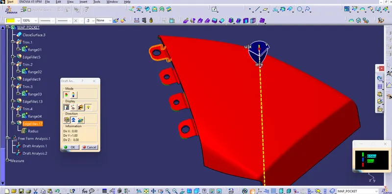
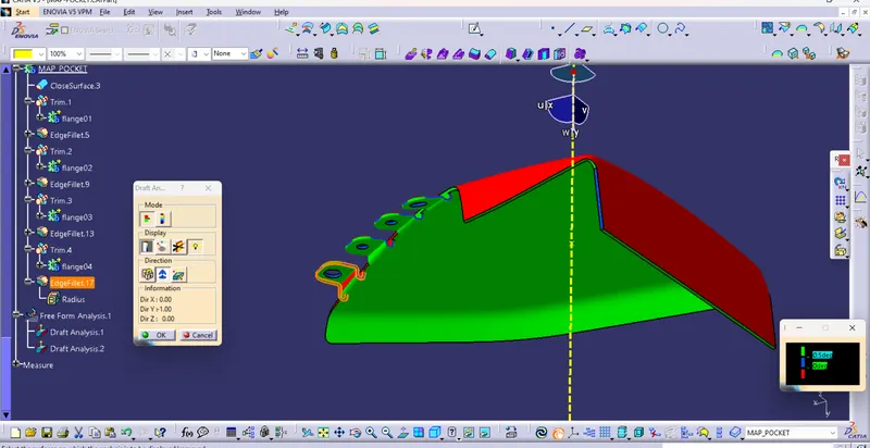
III) Perform Draft analysis on Class A surface
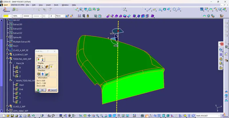
IV) Create a Class B surface
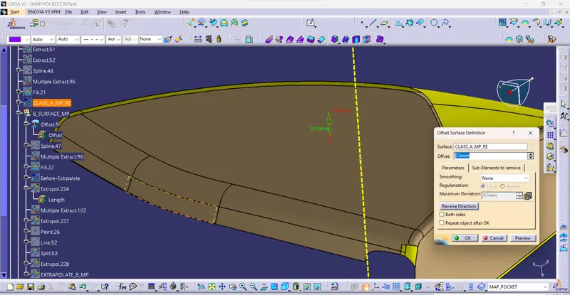
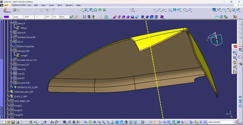
V) Create a Class C surface
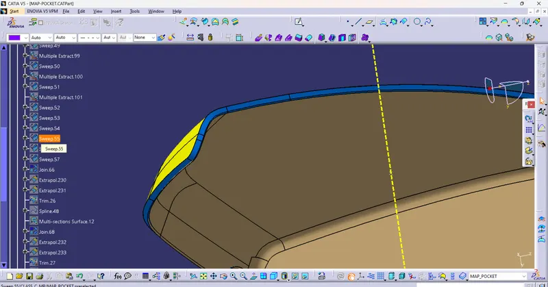
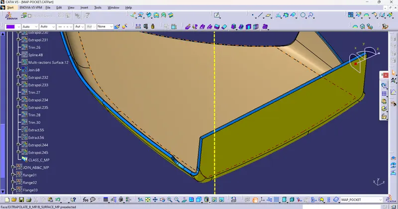
VI) Close all A, B, and C surfaces and make a Close Surface Feature
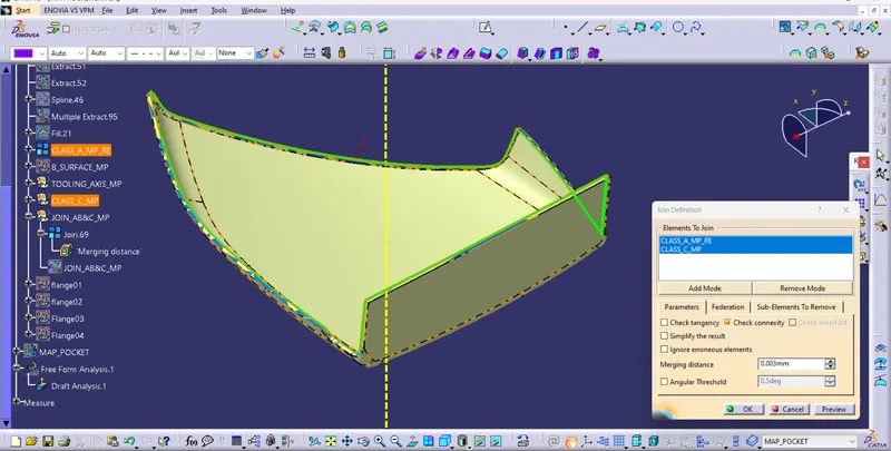
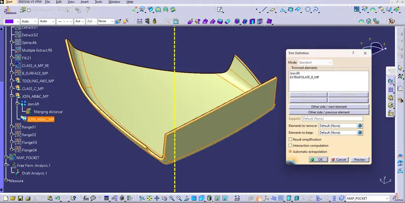
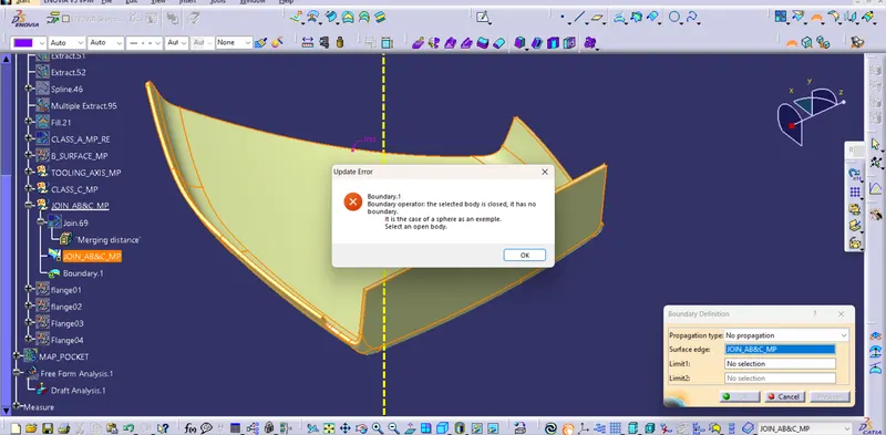
VII) Create solid Feature From Close surfaces
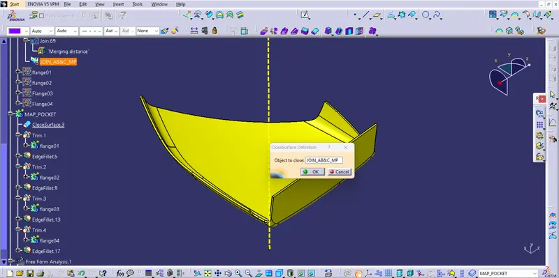
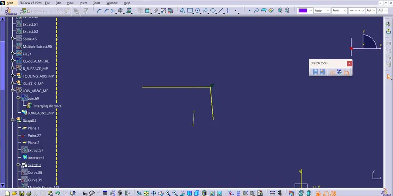
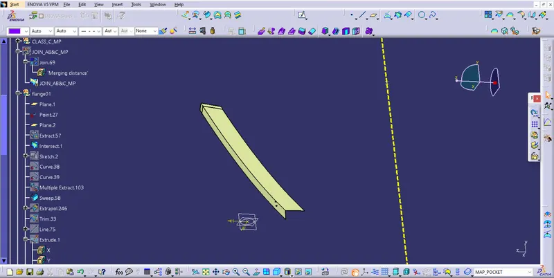
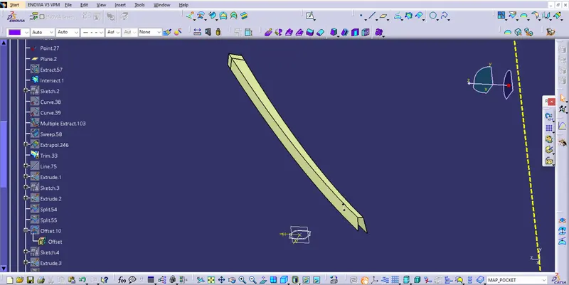
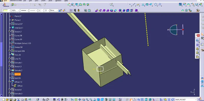
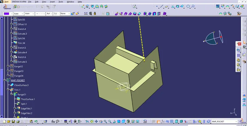
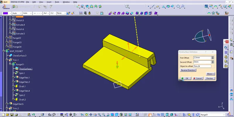
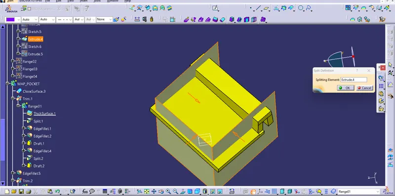
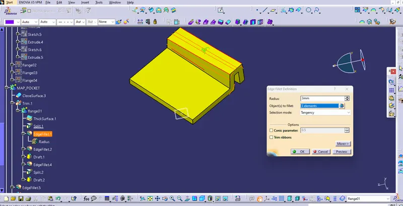
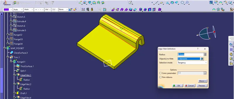
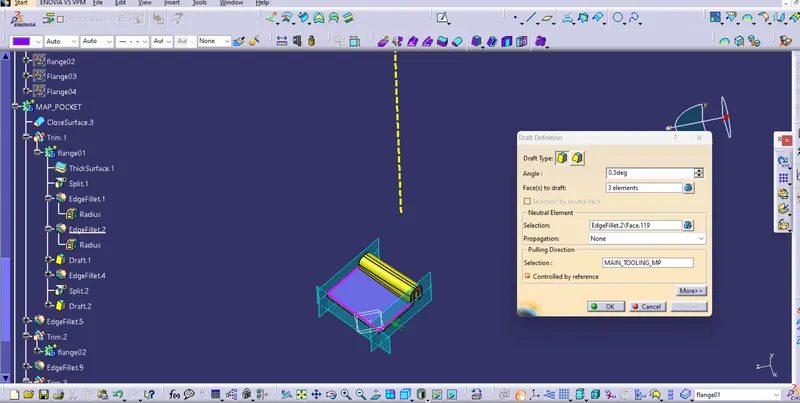
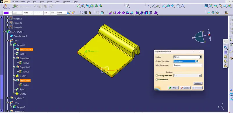
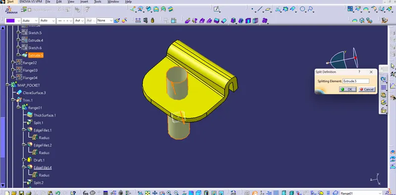
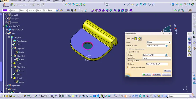
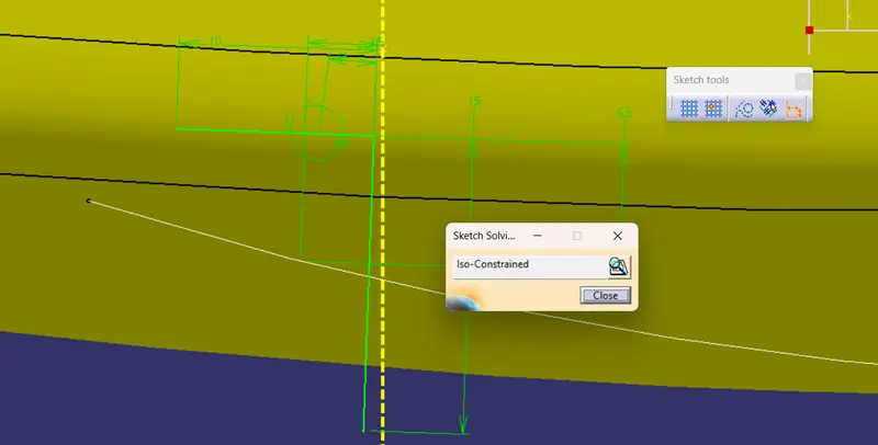
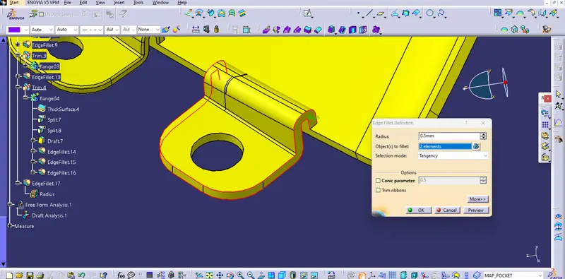
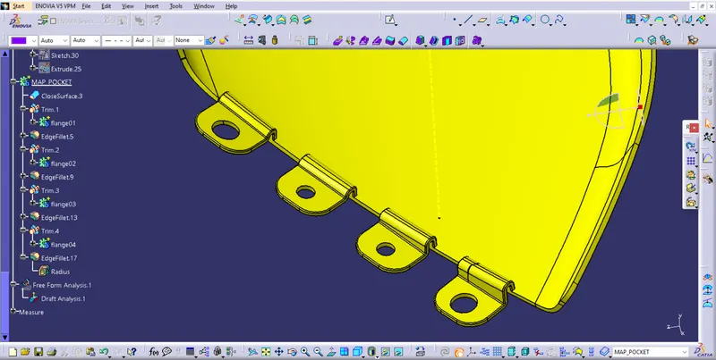
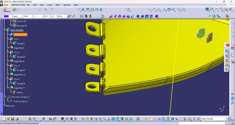
VIII) Create Flange for Heat stakes and Locators
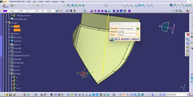
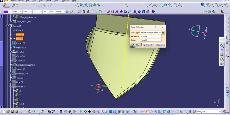
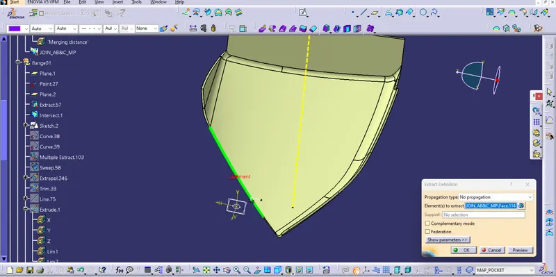
C) Bottle Holder
I) Get Input as Class A surface
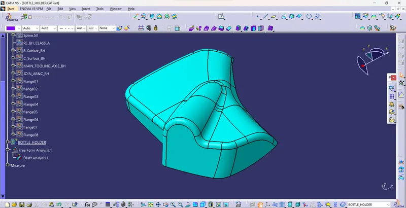
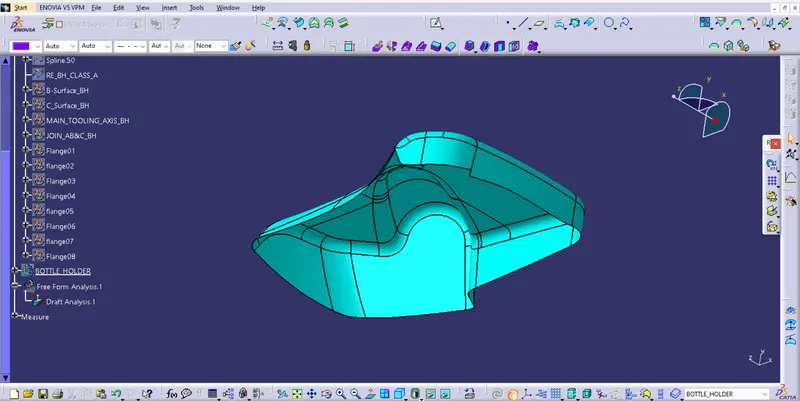
II) Create the Main tooling axis By using the appropriate Method
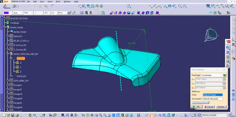
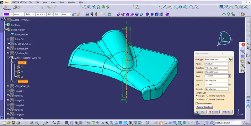
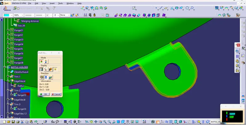
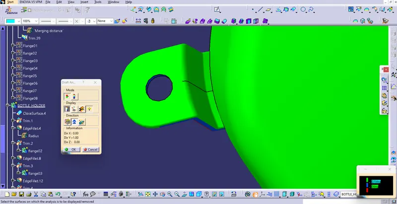
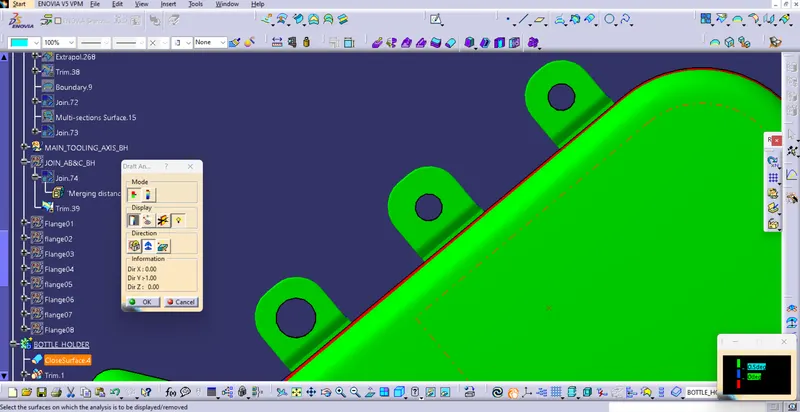
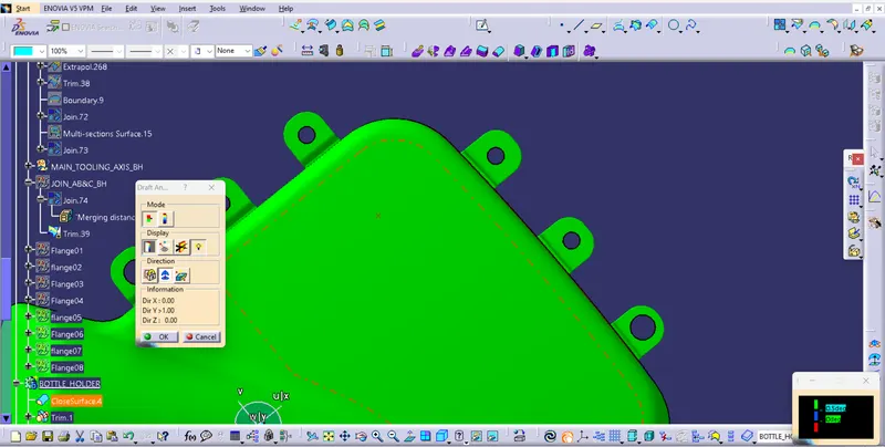
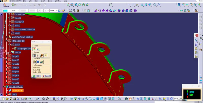
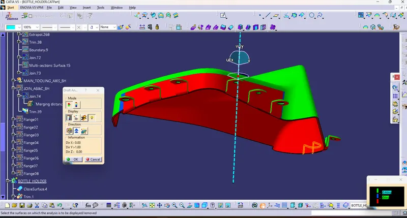
III) Perform Draft analysis on Class A surface
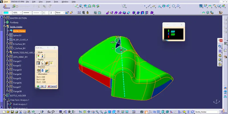
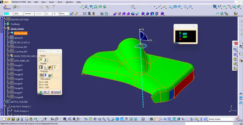
Note :- We notice the Problem With Non clearance of Some Surfaces, To clear this Surface we have to Redesign With Class A surface Designer, Tooling axis is Locked With other Components which are Going to be assembled Together.
IV) Create a Class B surface
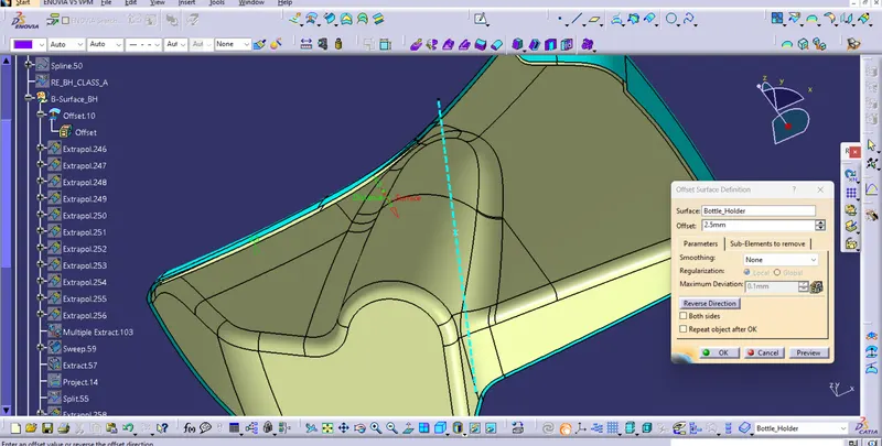
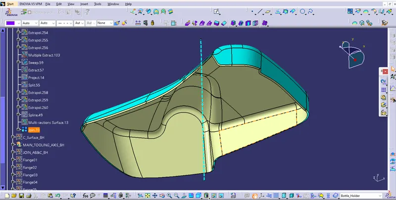
V) Create a Class C surface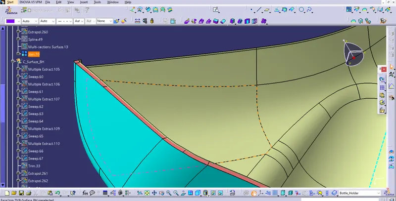
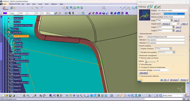
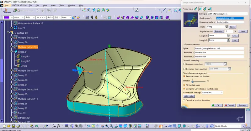
VI) Close all A, B, and C surfaces and make a Close Surface Feature
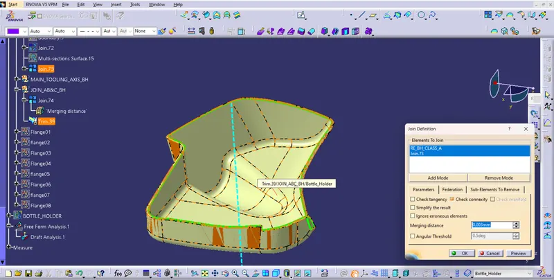
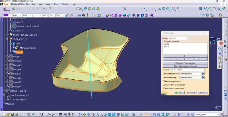
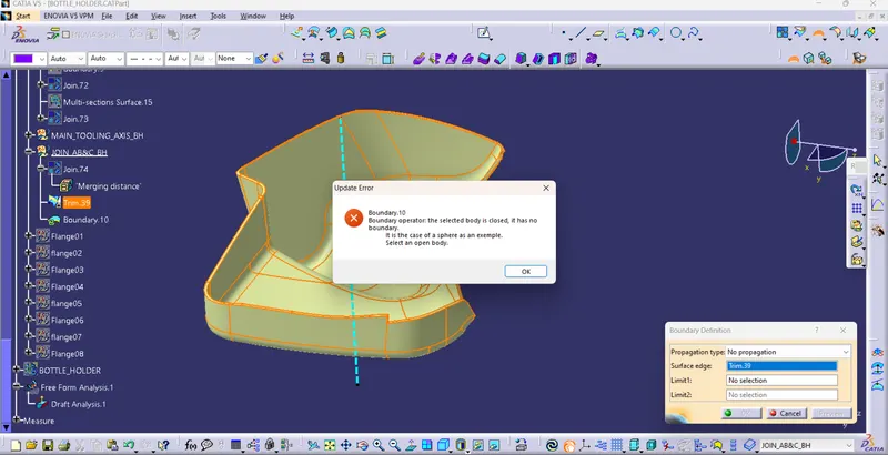
VII) Create solid Feature From Close surfaces
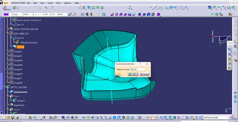
VIII) Create Flanges
A) Base Sketch
a) choose or create a Plane where points Located
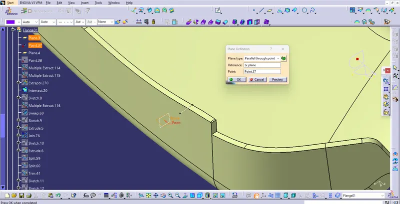
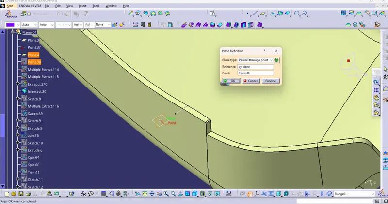
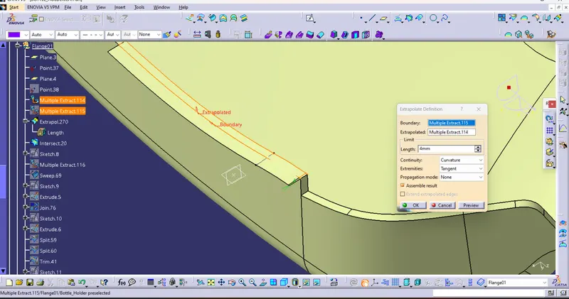
b) Perform Sketch and Surface operations to achive Base surface for split operation
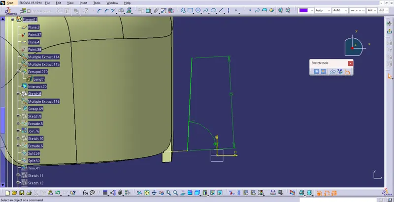
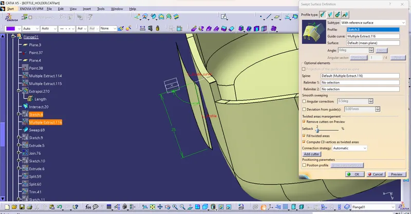
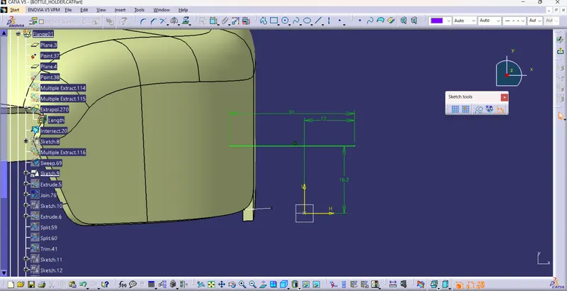
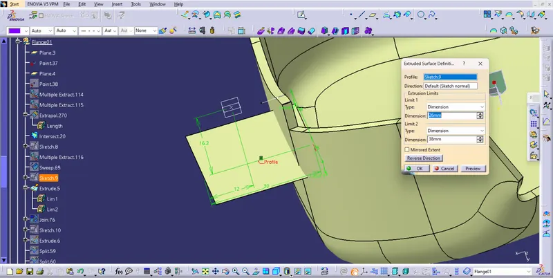
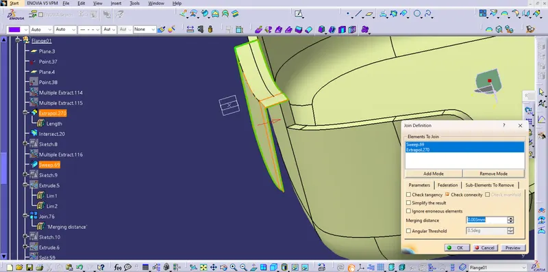
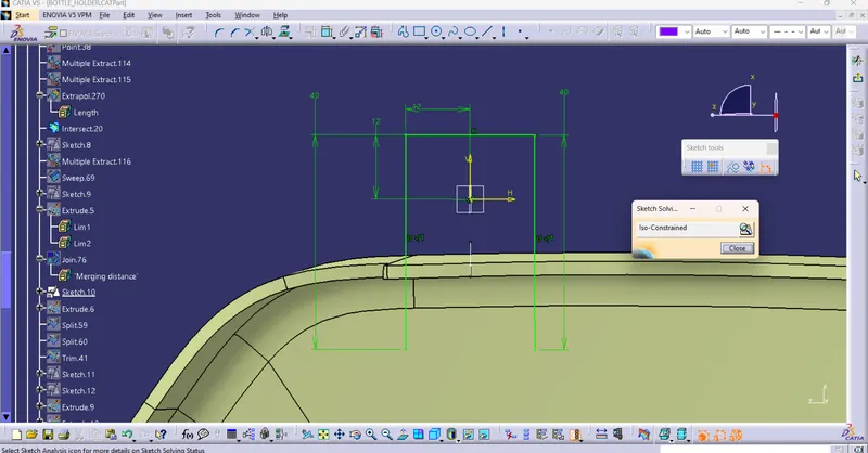
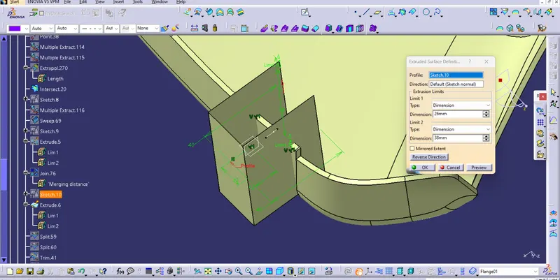
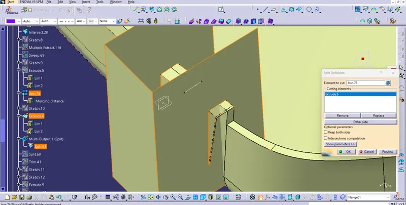
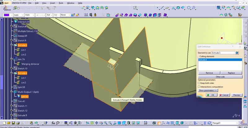
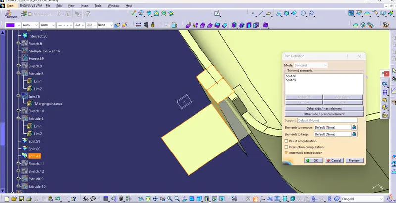
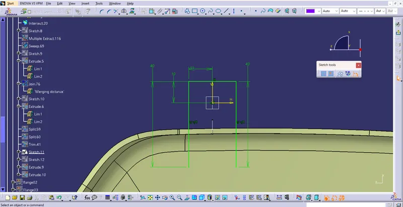
c) Perform Solid Body operations
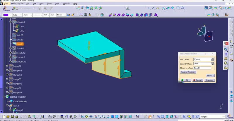
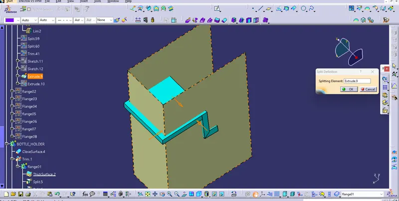
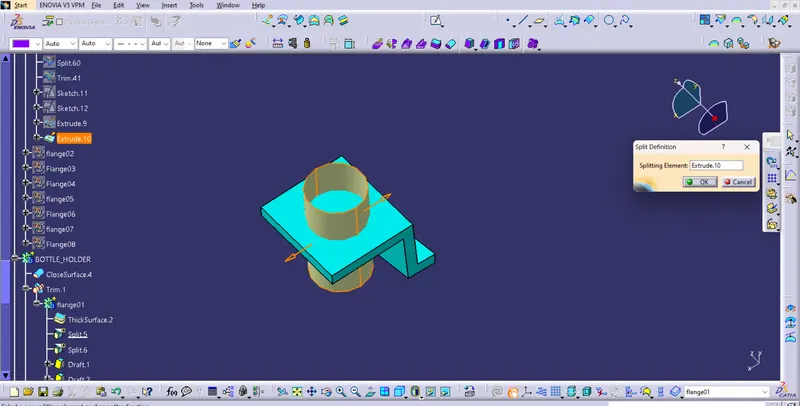
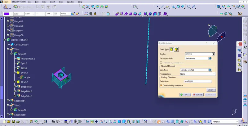
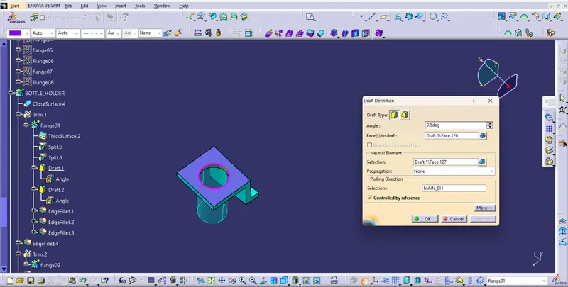
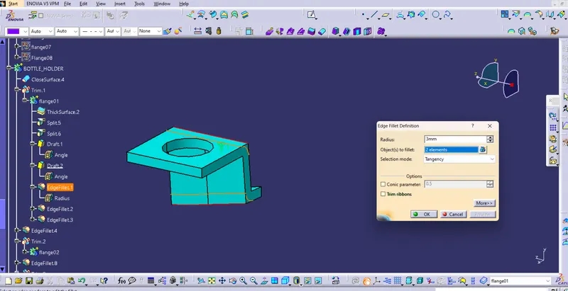
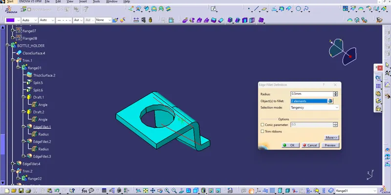
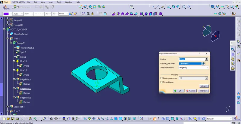
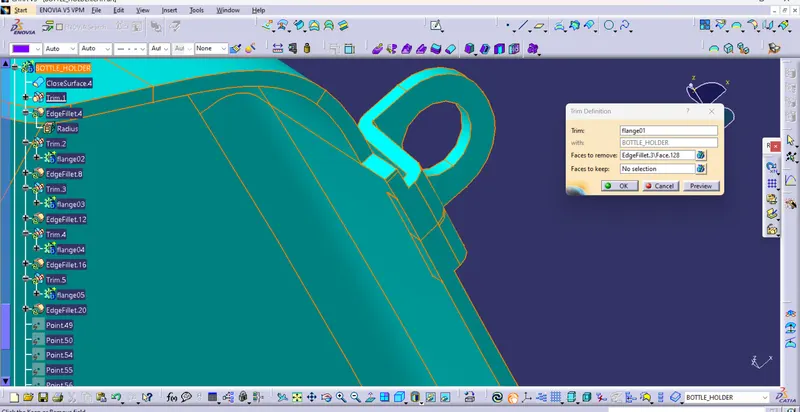
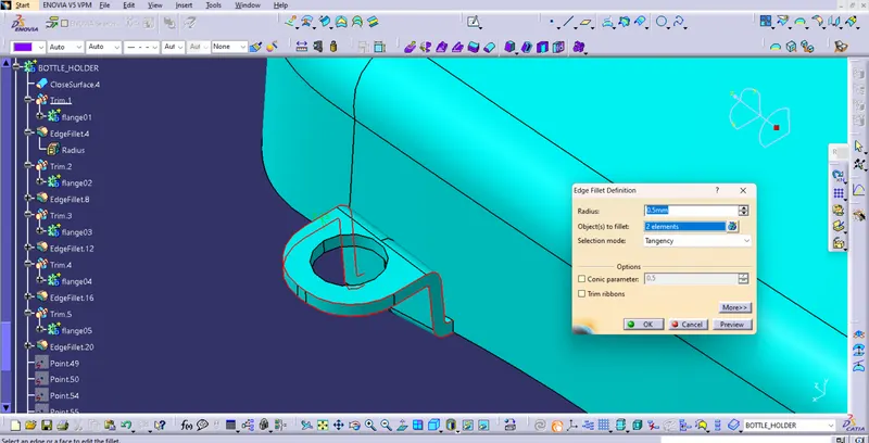
d) Perform same operations to create other flanges
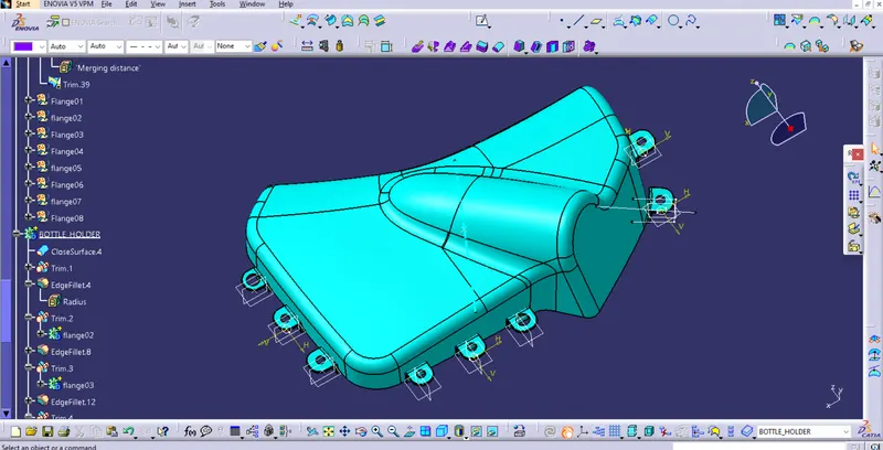
B) Perform Draft analysis on the Complete Featured Body
D) Arm Rest
I) Get Input as Class A surface
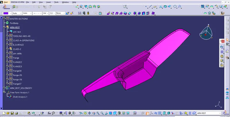
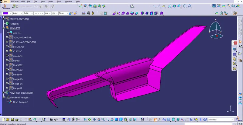
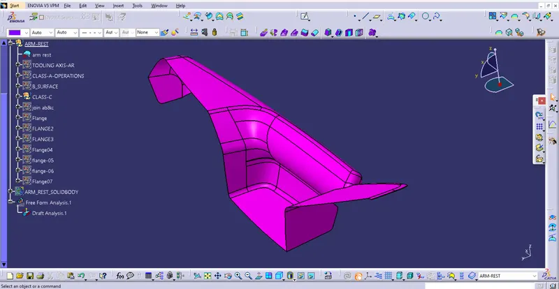
II) Create the Main tooling axis By using the appropriate Method
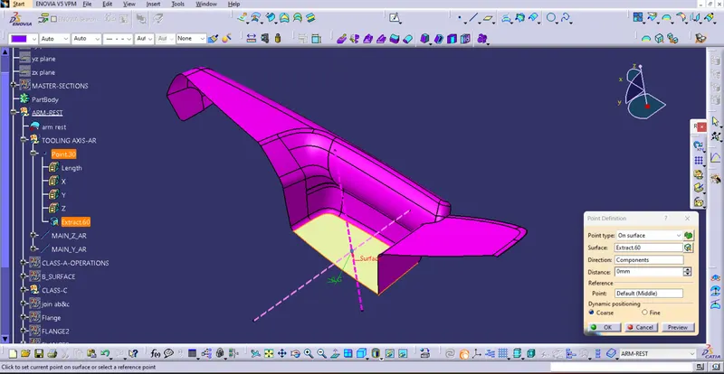
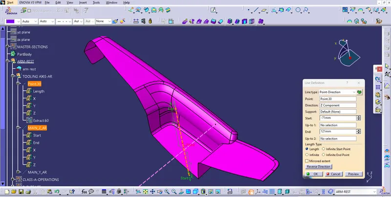
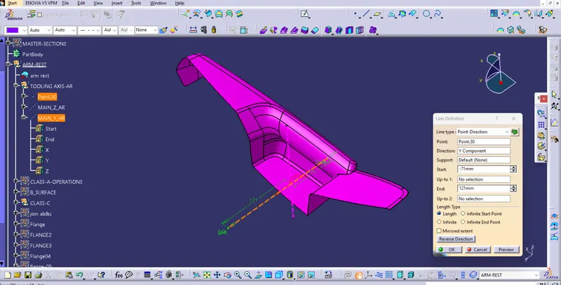
III) Perform Draft analysis on Class A surface
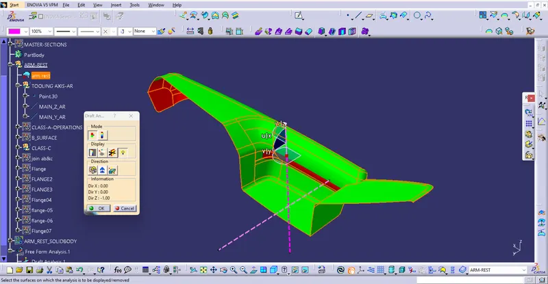
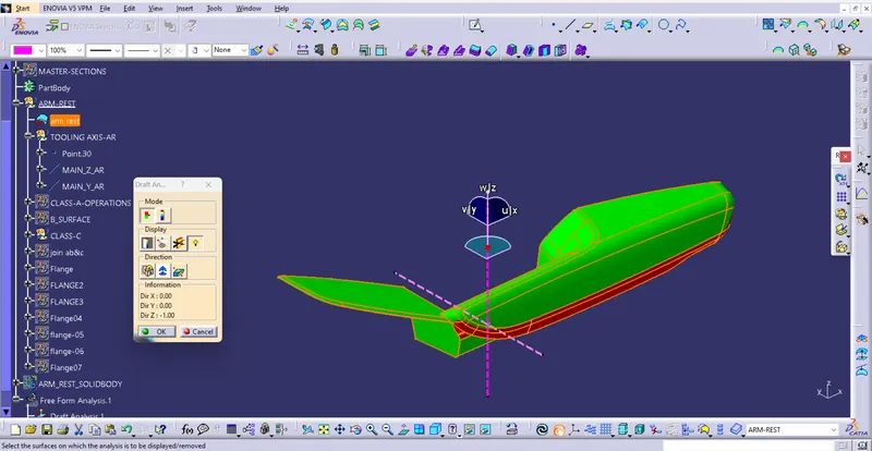
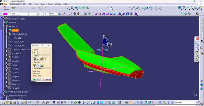
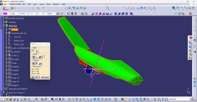
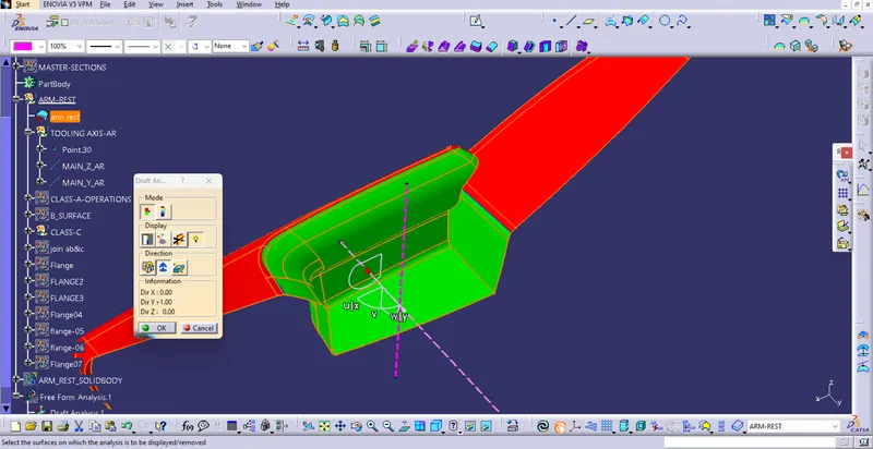
IV) Create a Class B surface
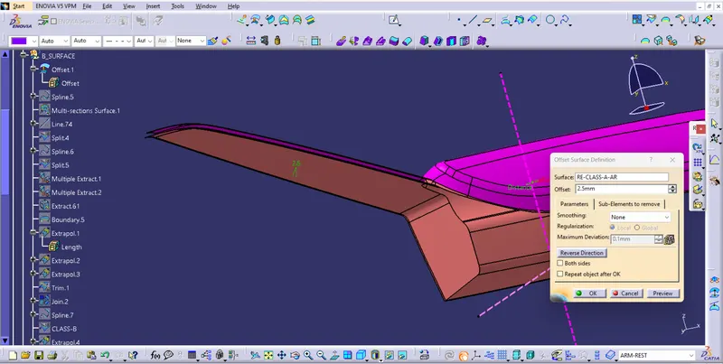
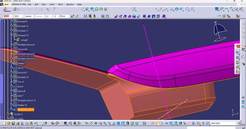
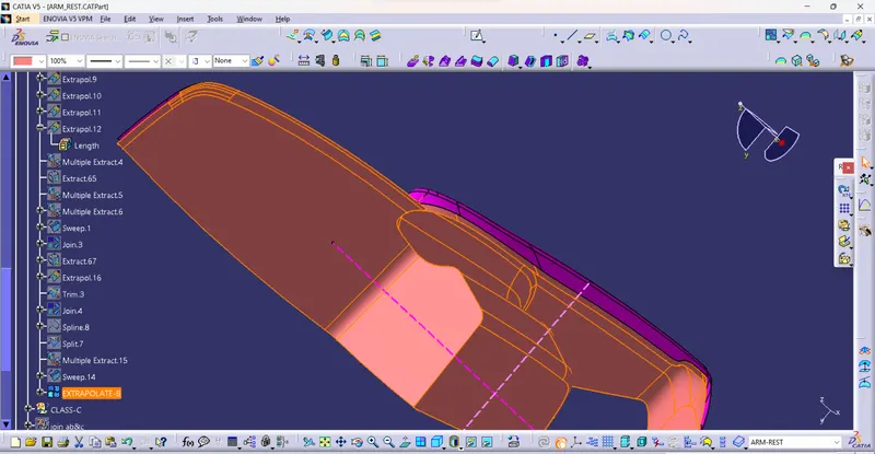
V) Create a Class C surface
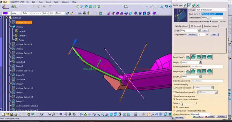
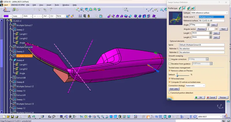
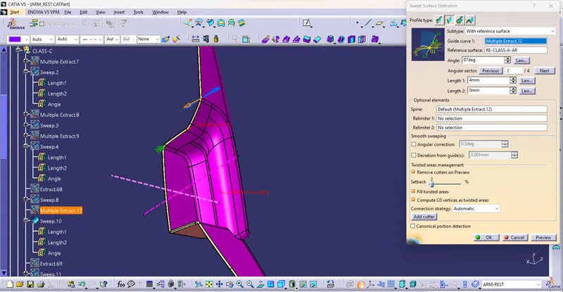
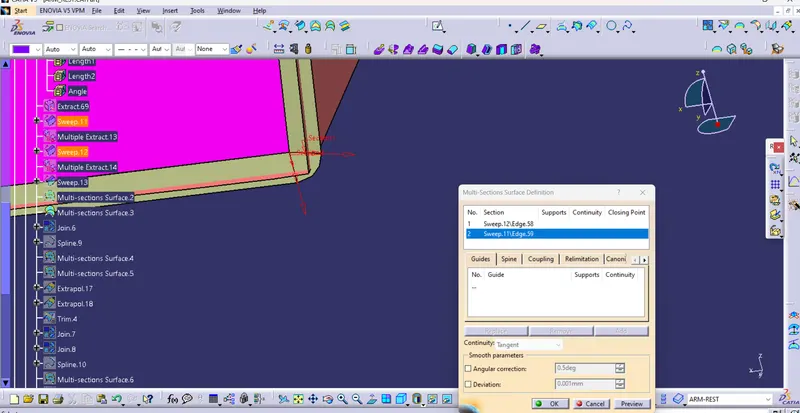
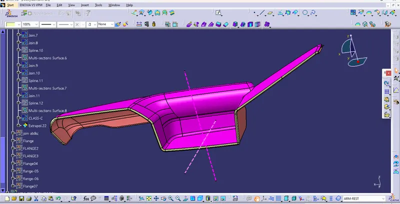
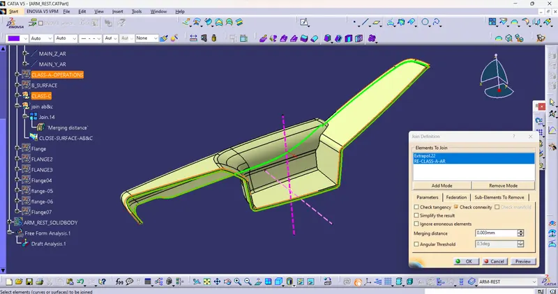
VI) Close all A, B, and C surfaces and make a Close Surface Feature
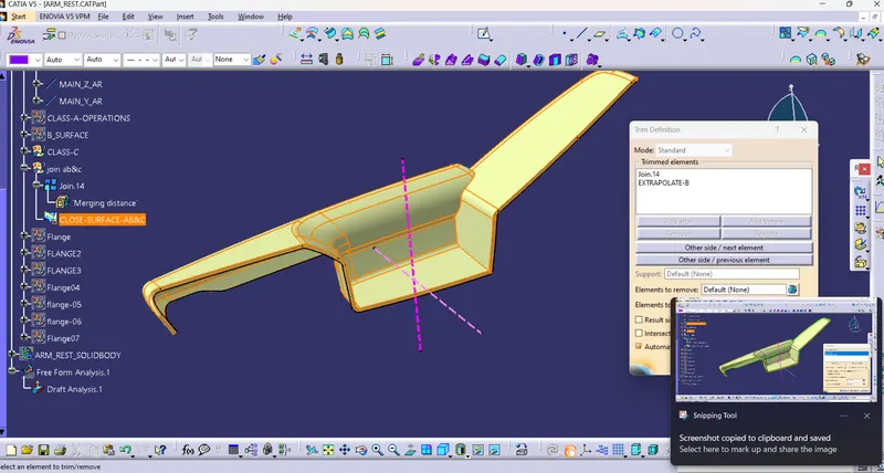
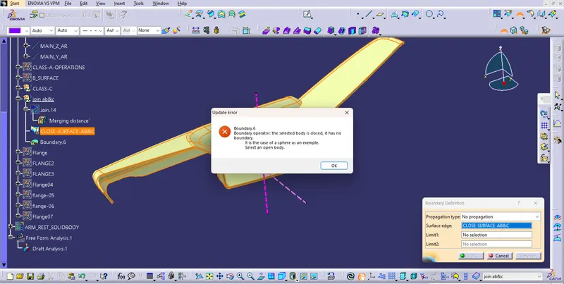
VII) Create solid Feature From Close surfaces
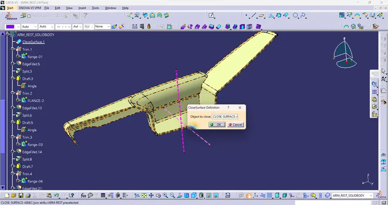
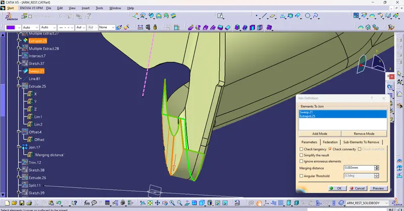
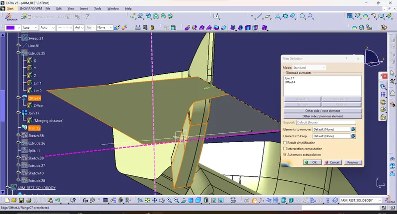
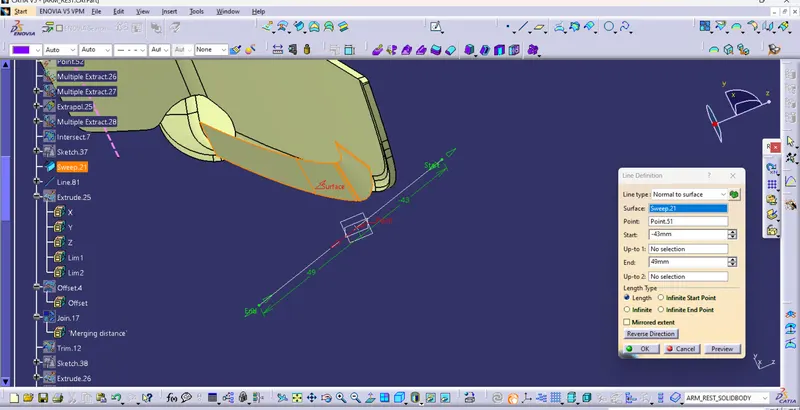
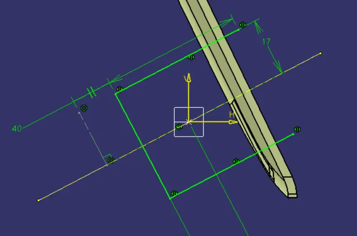
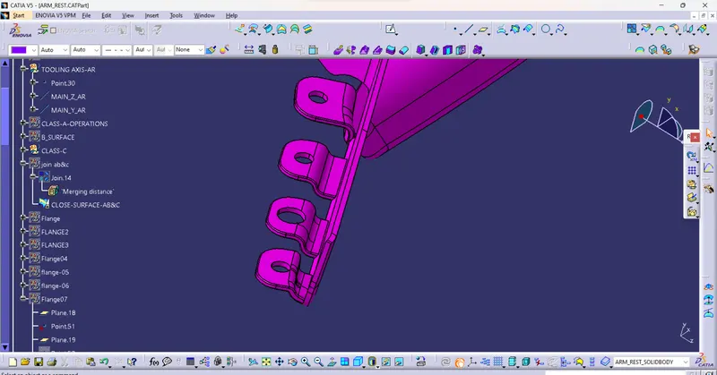
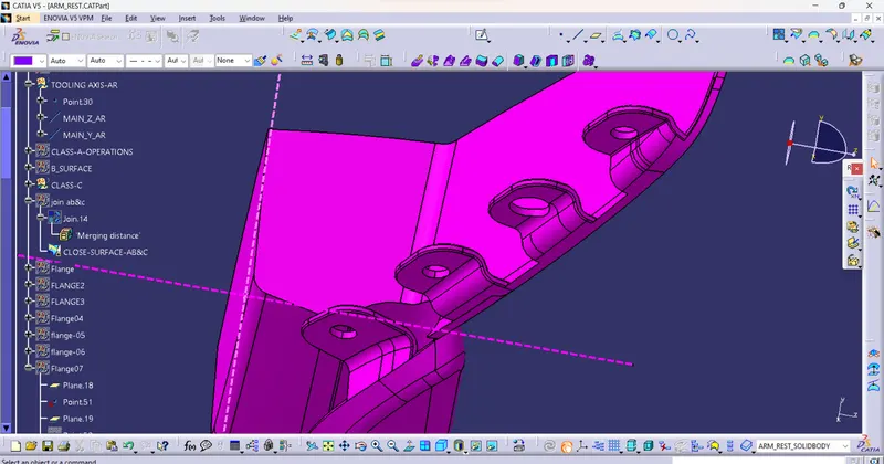
VIII) Create Flanges for Heat stakes and locators
A) Base Sketch
a) choose or create a Plane where points Located
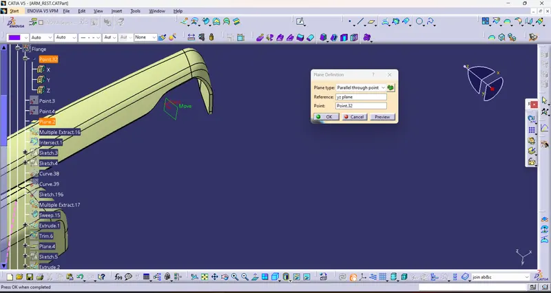
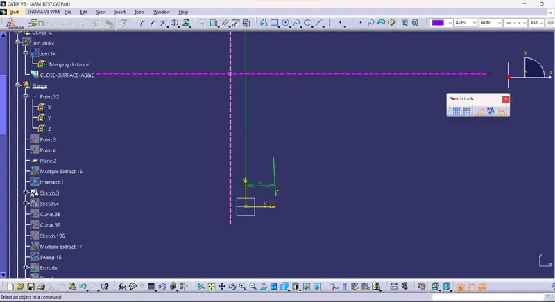
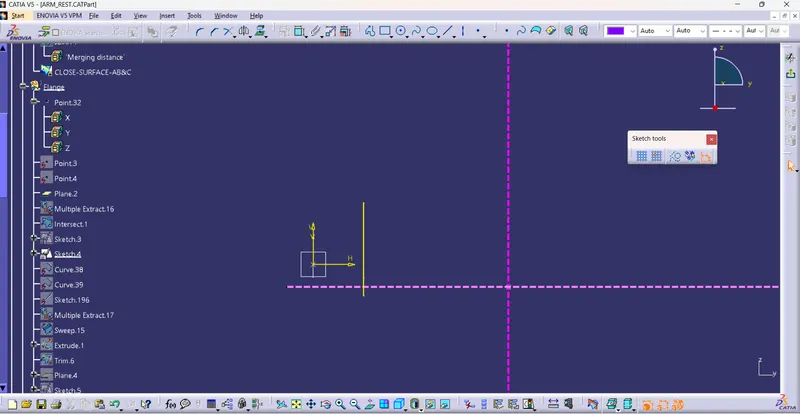
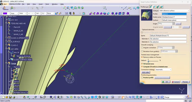
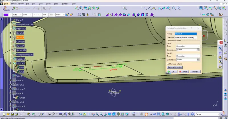
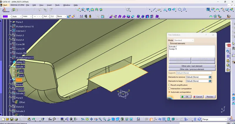
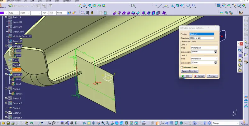
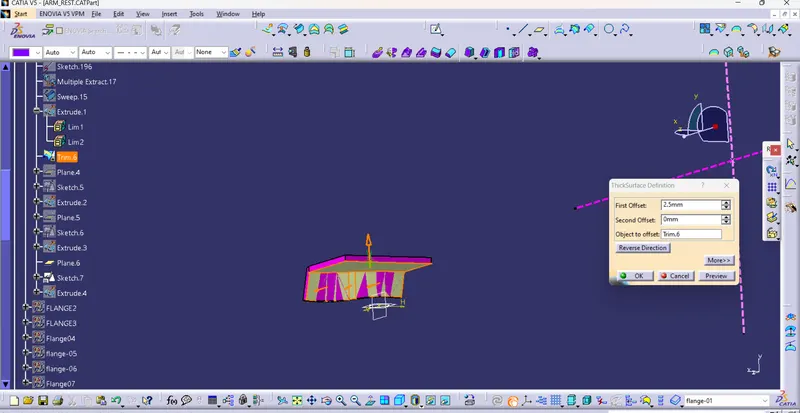
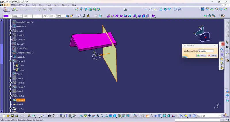
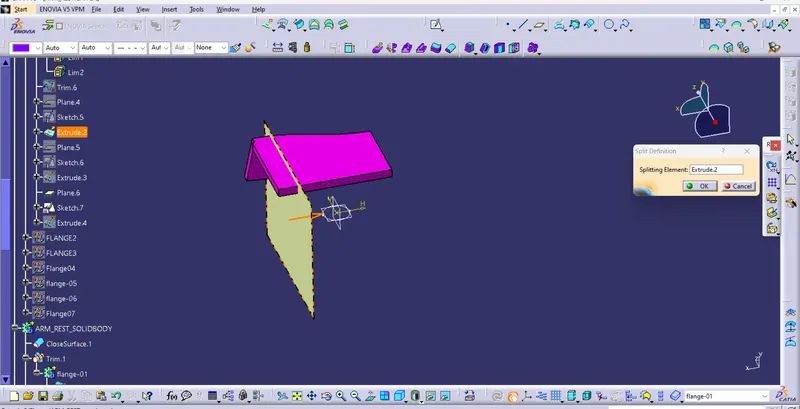
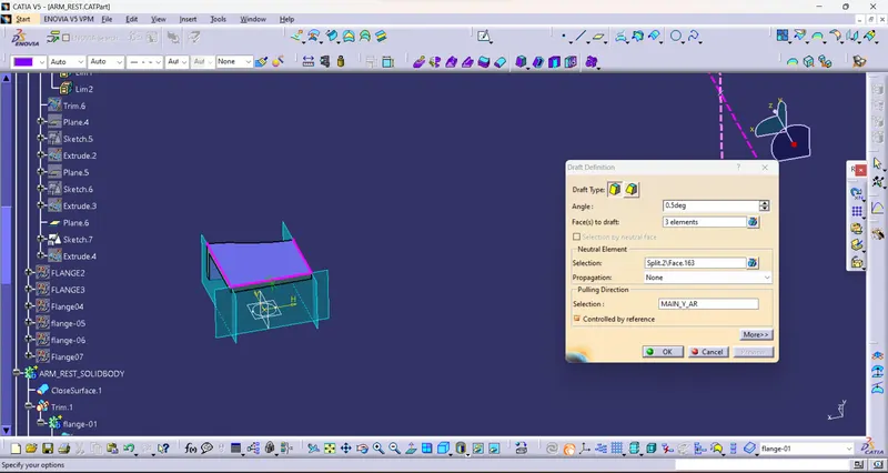
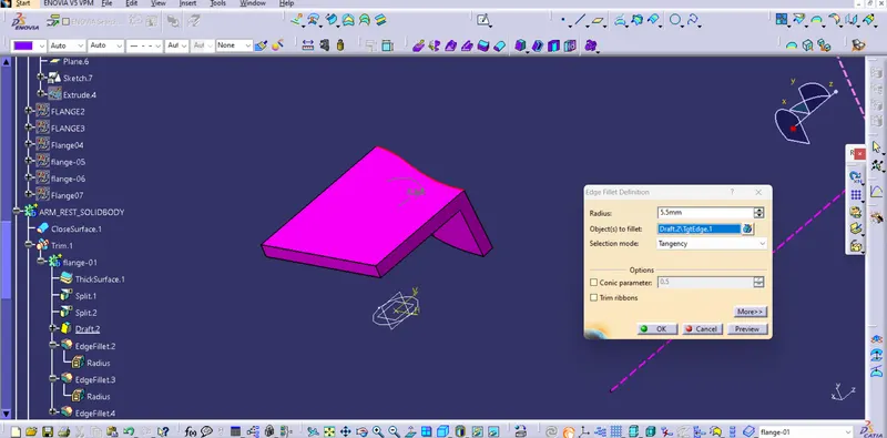
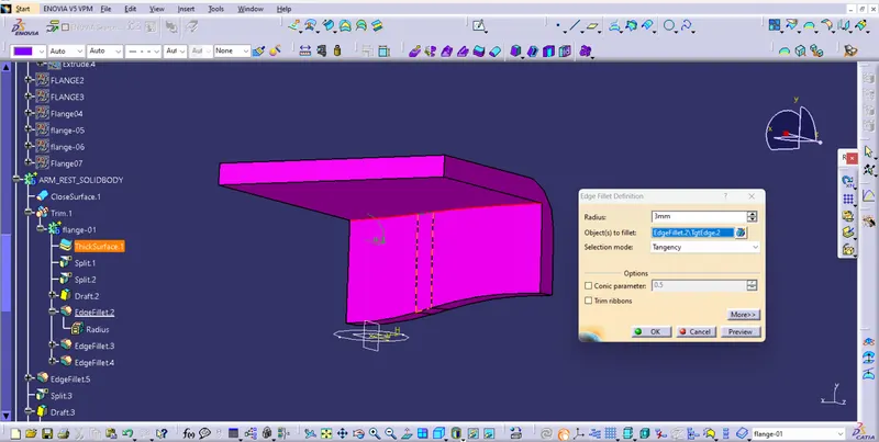
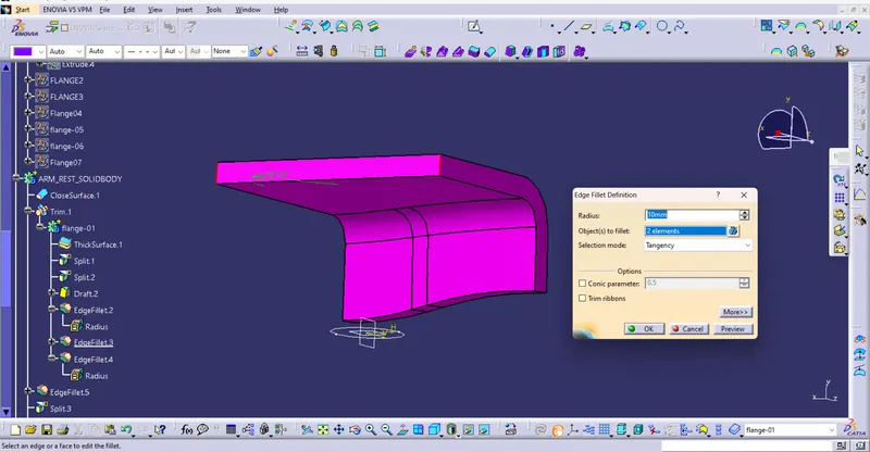
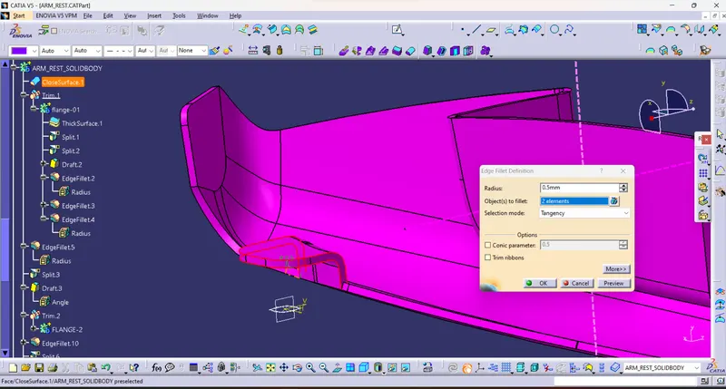
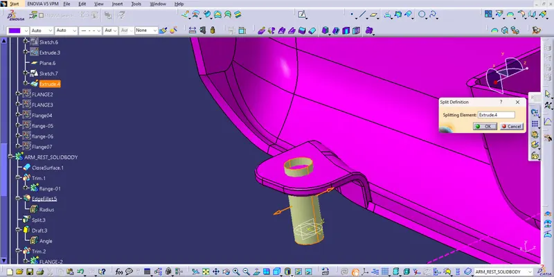
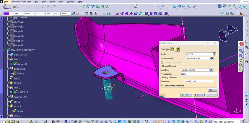
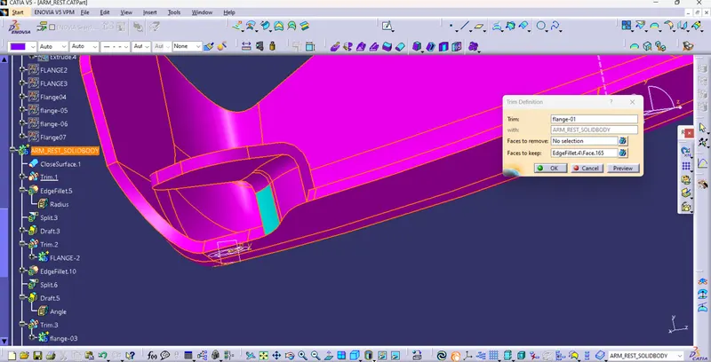
b) Create a extended flange
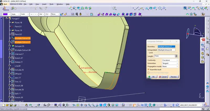
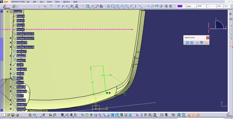
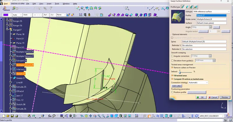
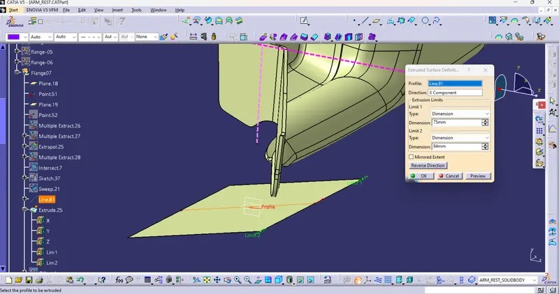
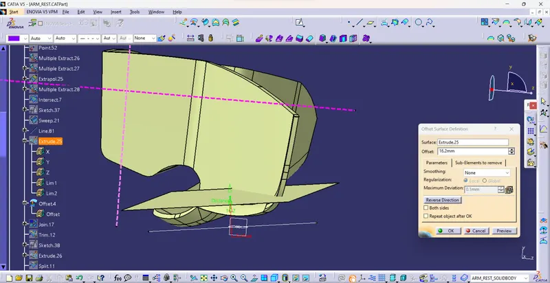
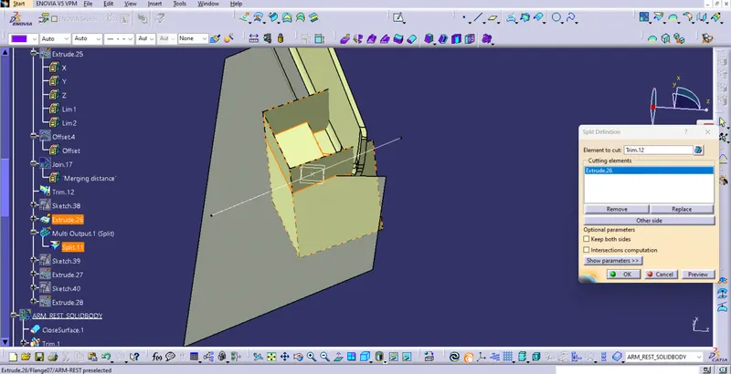
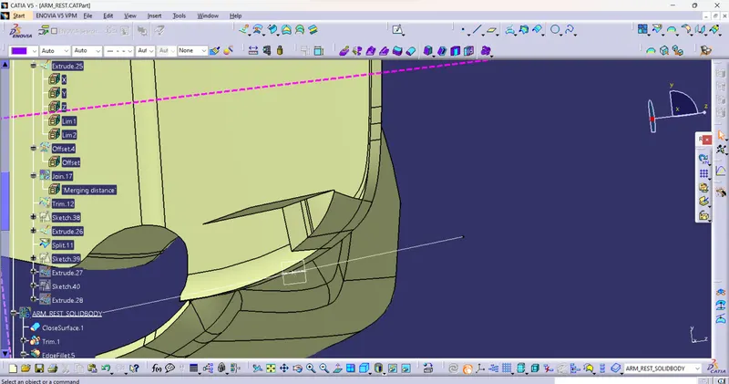
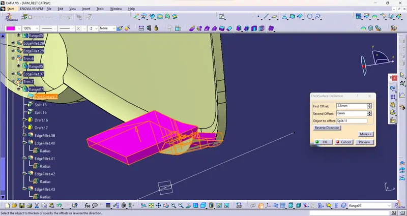
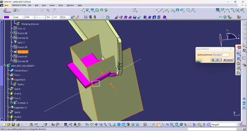
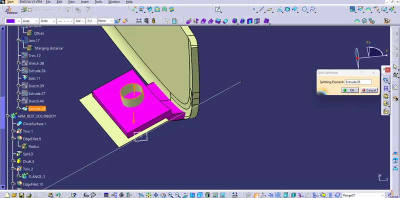
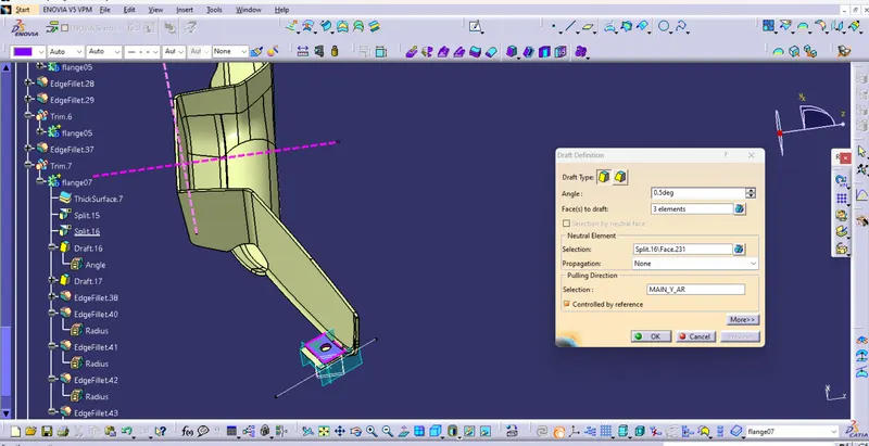
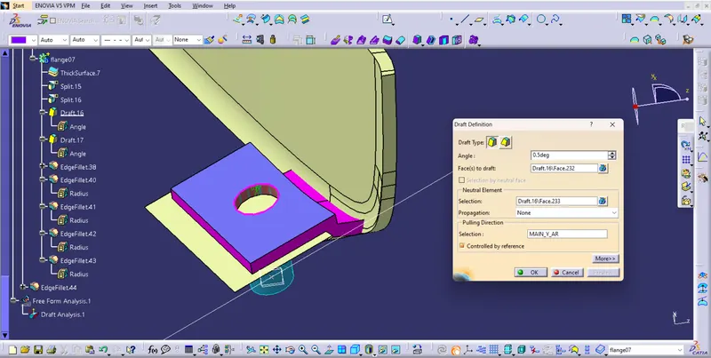
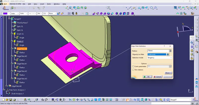
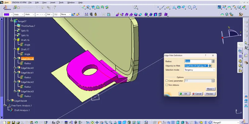
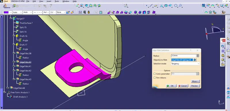
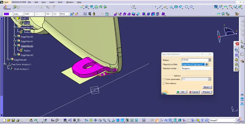
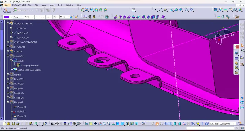
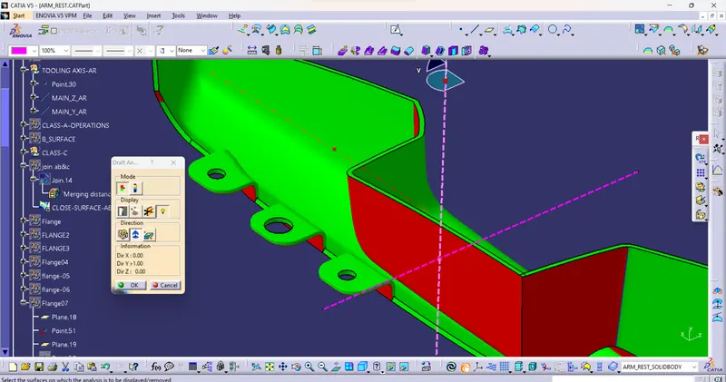
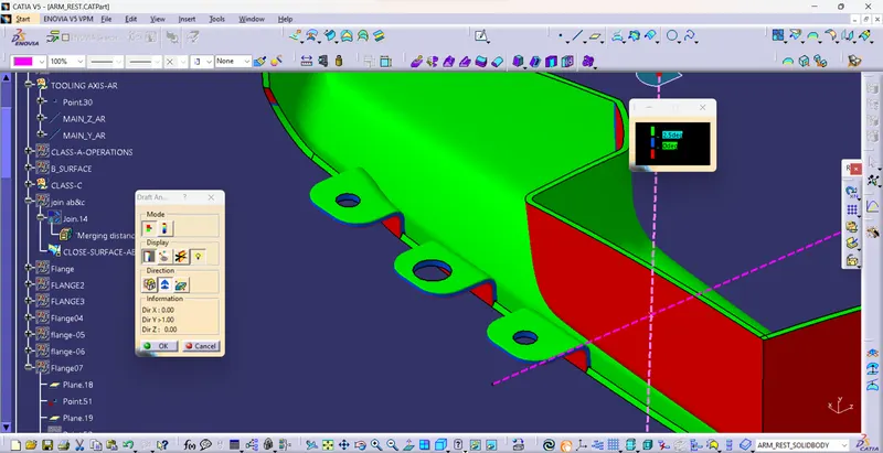
B) Perform Draft analysis on the Complete Featured Body
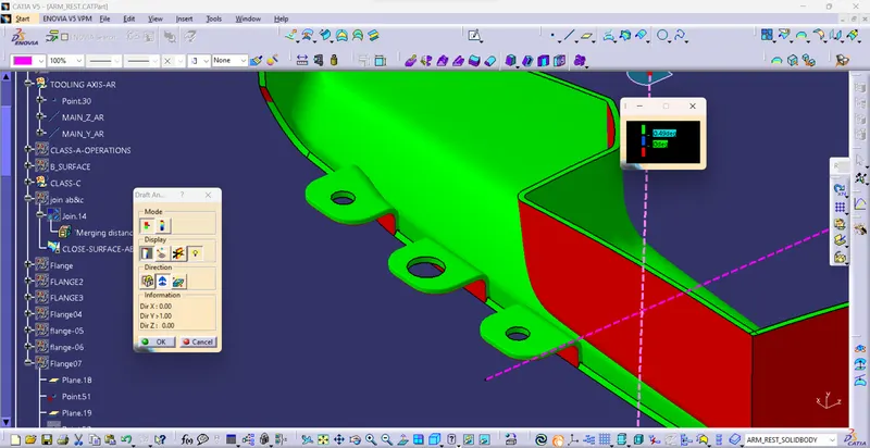
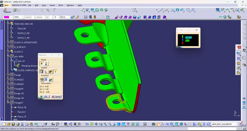
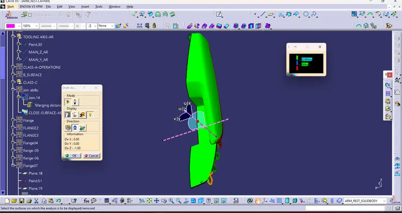
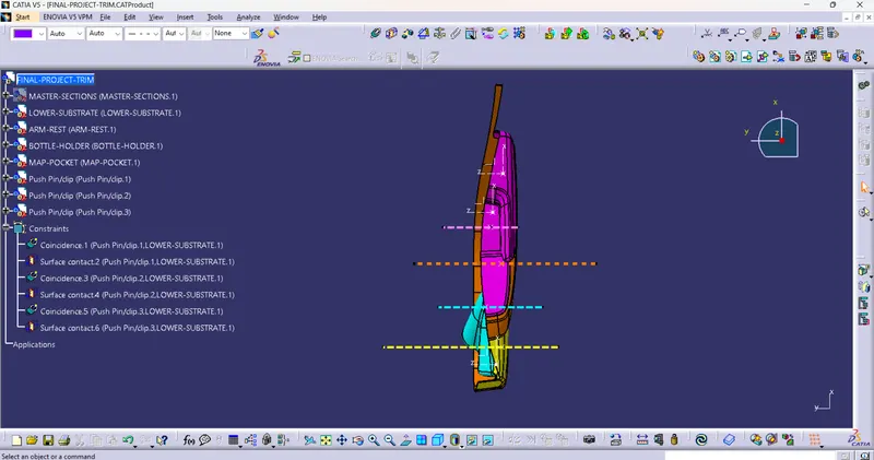
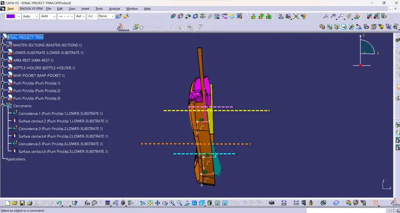
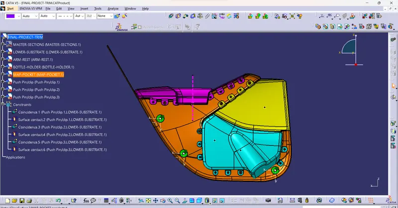
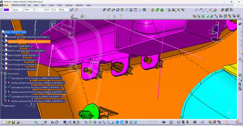
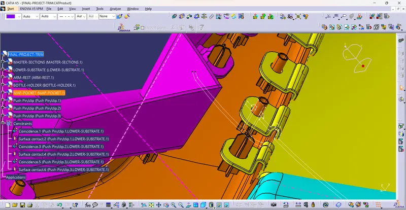
2) Create an Assembly with all components
A) Insert Parts in the Assembly workbench
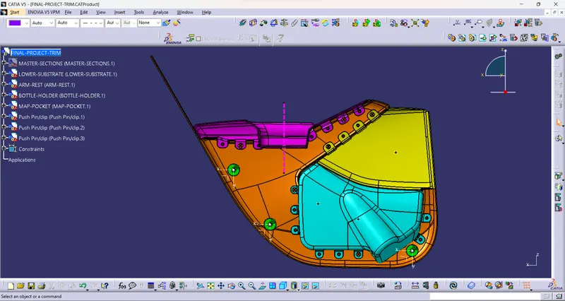
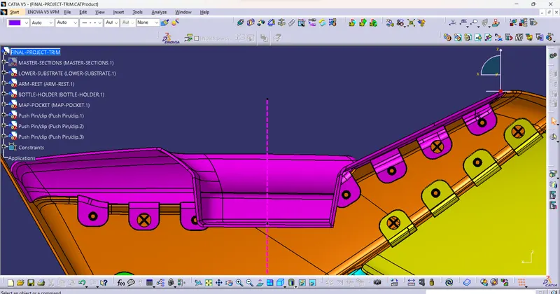
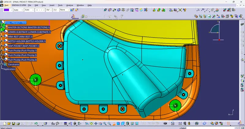
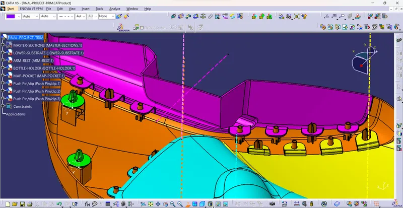
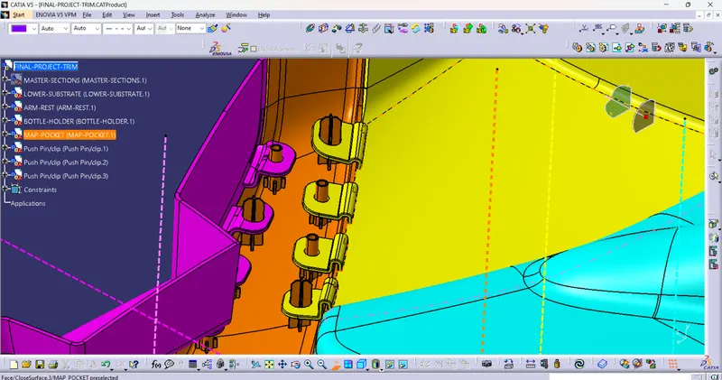
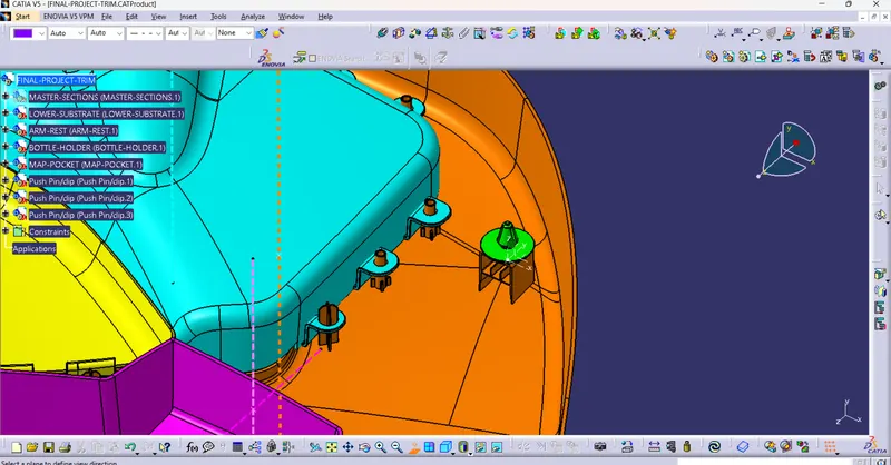
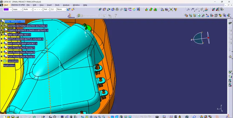
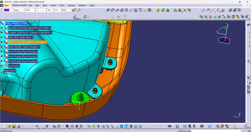
B) Give Appropriate Mates
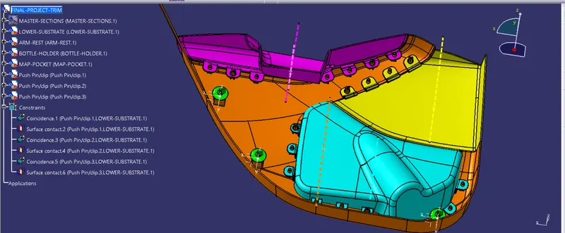
C) ISO/FV/SV View
Important notes :
- Heat stakes:
- Heat stakes are small plastic protrusions or stakes that are formed by melting or deforming plastic during the manufacturing process.
- These stakes are used to securely fasten or join plastic components together.
- Heat stakes provide mechanical strength and stability to the assembled parts, ensuring they stay in place even under vibration or stress.
- Eliminate the need for additional fasteners such as screws or adhesives, simplifying the assembly process and reducing costs.
- Locators:
- Locators are specific features or shapes incorporated into plastic parts that aid in proper alignment and positioning during assembly.
- Act as reference points, allowing precise mating and alignment of different components.
- Accurate alignment and locators contribute to the overall quality and fitment of the assembled interior parts.
- streamline the assembly process, reducing the likelihood of misalignment or errors during production.
-
Pushpins are commonly used in the assembly of plastic interior parts in cars, particularly with dog houses.
- Use of Pushpins: Pushpins, also known as panel clips or trim clips, are fasteners used to securely attach plastic components to the car's interior. They consist of a cylindrical body with a flared or ribbed head and a pointed tip. Pushpins provide a reliable and removable connection, allowing easy access to hidden components or panels for maintenance or repair purposes. They are often used to secure trim panels, dashboard components, door panels, and other plastic parts in the car's interior.
- Assembly with Doghouses: In the context of plastic interior parts, doghouses refer to recessed or encapsulated areas designed to house electrical connectors, switches, or other components. When assembling plastic parts with doghouses, pushpins play a crucial role in securely fastening the components in place.
The assembly Procedure :
- a) Positioning: The plastic component with the doghouse is aligned and positioned correctly on the car's interior structure or adjacent part.
- b) Aligning the Pushpin: The pushpin is aligned with the pre-drilled hole in the doghouse or the corresponding hole in the car's interior structure.
- c) Insertion: The pointed tip of the pushpin is inserted into the hole, and pressure is applied to push it through until the flared or ribbed head of the pushpin reaches the surface of the plastic component.
- d) Locking: The flared or ribbed head of the pushpin locks into place, creating a secure connection. The pushpin's design ensures that it remains firmly attached to both the plastic component and the car's interior structure.
This assembly method provides a reliable and removable attachment, allowing easy disassembly if needed while ensuring the plastic components stay securely in place during regular use.
Overall, pushpins are essential fasteners in the assembly of plastic interior parts, particularly in conjunction with doghouses, providing a secure and accessible connection that facilitates efficient manufacturing, assembly, and maintenance of the car's interior.