Week 11 - Simulation of Flow through a pipe in OpenFoam
INTRODUCTION
In this challenge we have to simulate a flow through a pipe using OpenFoam.The flow is taken to be a laminar flow of 2100 reynolds number.The results obtained after the simulation is validated using the Hagen-Poiseuille equation.Also we are required to
1.Calculate the hydrdynamic length and validate the velocity profile for the fully developed flow.
2.Validate max pressure drop and max velocity.
3.Validate wall shear stress for fully developed flow.
THEORY
Hydrodynamic Length
The length from the inlet after which the flow becomes fully developed is called as hydrodynamic or entrance length.It is also the length from the inlet where the boundary layer engulfs the entire pipe. Fully developed region is where the velocity of the fluid remains unchanged in the axial direction.
For laminar flow , the hydrodynamic length can be approximately calculated using the formula
`L_e=0.06R_eD`
where
`L_e` = Hydrodynamic Length(m)
`R_e` = Reynolds Number
`D` = Diameter of pipe (m)
STEPS
PRE-PROCESSING
I. Selection of Solver
The icoFoam solver inside the incompressible directory is selected as the solver as it solves the incompressible navier stokes equation for laminar flow (Fluid=water(incompressible),Reynolds Number=2100<2300(Laminar)).
II. blockMeshDict
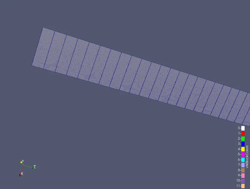
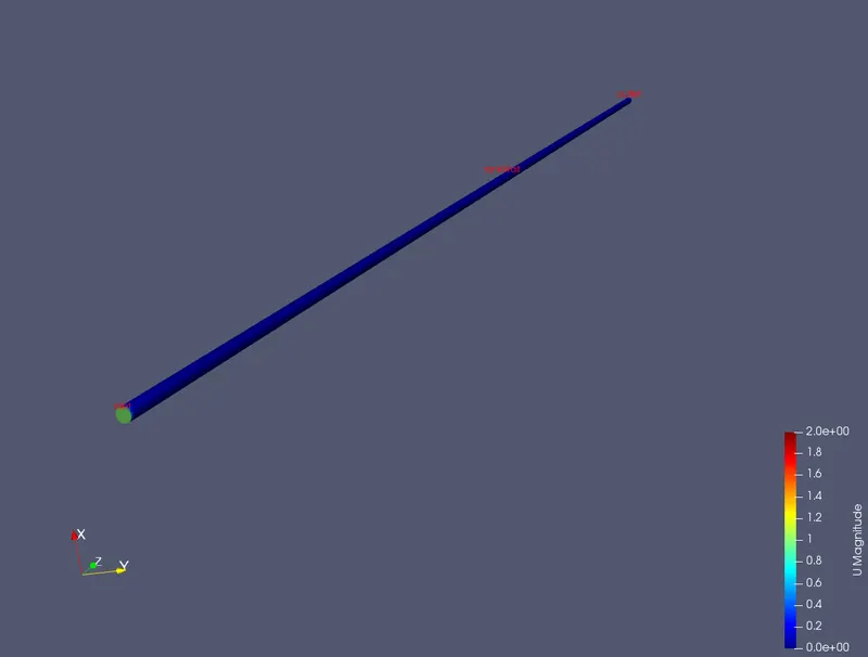
The geometry is modified to a wedge block having diameter=0.02m,Length=3m with a wedge angle of 4 degrees.The geometry is modified in the blockMeshDict file.
The wedge's length is along the z axis,with the thickness along y axis.
/*--------------------------------*- C++ -*----------------------------------*\
  =========                 |
  \\      /  F ield         | OpenFOAM: The Open Source CFD Toolbox
   \\    /   O peration     | Website:  https://openfoam.org
    \\  /    A nd           | Version:  8
     \\/     M anipulation  |
\*---------------------------------------------------------------------------*/
FoamFile
{
    version     2.0;
    format      ascii;
    class       dictionary;
    object      blockMeshDict;
}
// * * * * * * * * * * * * * * * * * * * * * * * * * * * * * * * * * * * * * //

convertToMeters 1;

vertices
(
    (0 0 0)
    (0.00999 0.00000609 0)
    (0.00999 0.00000609 3)
    (0 0 3)
    (0.00999 -0.00000609 0)
    (0.00999 -0.00000609 3)
);

blocks
(
    hex (0 4 1 0 3 5 2 3) (50 1 1000) simpleGrading (1 1 1)
);

edges
(
);

boundary
(
    front
    {
        type wedge;
        faces
        (
            (0 1 2 3)
        );
    }

    back
    {
        type wedge;
        faces
        (
            (0 3 5 4)
        );
    }

    tankWall
    {
        type wall;
        faces
        (
            (1 4 5 2)
        );
    }

    inlet
    {
        type patch;
        faces
        (
            (0 4 1 0)
        );
    }

    outlet
    {
        type patch;
        faces
        (
            (3 5 2 3)
        );
    }

    axis
    {
        type empty;
        faces
        (
            (0 3 3 0)
        );
    }
);

mergePatchPairs
(
);

// ************************************************************************* //
1.To find the coordinates of x and y from the given wedge angle and diameter. Convert the angle to radians and multiply it with the radius.
`x=0.05/2(cos((2pi)/180))`
`y=0.05/2(sin((2pi)/180))`
2.The blocks are then specified for the wedge geometry (0 4 1 0) being the lower triangle and (3 5 2 3 ) being the upper triangle.
3.The mesh size size was also given 50 divisions in the x axis and 1000 divisions in the z axis.
4.The boundary for the geometry were specified with the inlet and outlet being type patch, the upper tankWall being type wall and the two sides being type wedge.
III.controlDict
The controlDict file contains the information about the start time, end time,time step and various factors.
*--------------------------------*- C++ -*----------------------------------*\
  =========                 |
  \\      /  F ield         | OpenFOAM: The Open Source CFD Toolbox
   \\    /   O peration     | Website:  https://openfoam.org
    \\  /    A nd           | Version:  8
     \\/     M anipulation  |
\*---------------------------------------------------------------------------*/
FoamFile
{
    version     2.0;
    format      ascii;
    class       dictionary;
    location    "system";
    object      controlDict;
}
// * * * * * * * * * * * * * * * * * * * * * * * * * * * * * * * * * * * * * //

application     icoFoam;

startFrom       startTime;

startTime       0;

stopAt          endTime;

endTime         2;

deltaT          0.001;

writeControl    timeStep;

writeInterval   20;

purgeWrite      0;

writeFormat     ascii;

writePrecision  6;

writeCompression off;

timeFormat      general;

timePrecision   6;

runTimeModifiable true;


// ************************************************************************* //
1. The time step is calculated based on the condition that courant number(C)<1.
`delx=3/1000`
`=0.003`
`delt=(delx)/C`
`delt=0.003/1`
`=0.003`
Here when we assume that C=1 we get 0.003 to be the time step which satisfies the condition.Hence we can go with an even lesser value of delt=0.001 to be on the safer side.
2.The end time is taken to be 2.
3.Other values are kept as the default values.
IV. p and U
Since this is a transient solver initial conditions should be given for the pressure and velocity.
p
/*--------------------------------*- C++ -*----------------------------------*\
  =========                 |
  \\      /  F ield         | OpenFOAM: The Open Source CFD Toolbox
   \\    /   O peration     | Website:  https://openfoam.org
    \\  /    A nd           | Version:  8
     \\/     M anipulation  |
\*---------------------------------------------------------------------------*/
FoamFile
{
    version     2.0;
    format      ascii;
    class       volScalarField;
    object      p;
}
// * * * * * * * * * * * * * * * * * * * * * * * * * * * * * * * * * * * * * //

dimensions      [0 2 -2 0 0 0 0];

internalField   uniform 0;

boundaryField
{
    inlet
    {
        type            zeroGradient;
    }

    outlet
    {
        type            fixedValue;
        value		 uniform 0;
    }

    tankWall
    {
        type            zeroGradient;
    }

    front
    {
        type		wedge;
    }

    back
    {
    	type		wedge;
    }
}

// ************************************************************************* //
1.Pressure in the inlet and tankWall is given to be of zero gradient meaning that the pressure along the flow direction in the inlet is constant.
2.Pressure in the outlet is give a fixedValue of 0.
3.The wedges are given type wedge.
U
/*--------------------------------*- C++ -*----------------------------------*\
  =========                 |
  \\      /  F ield         | OpenFOAM: The Open Source CFD Toolbox
   \\    /   O peration     | Website:  https://openfoam.org
    \\  /    A nd           | Version:  8
     \\/     M anipulation  |
\*---------------------------------------------------------------------------*/
FoamFile
{
    version     2.0;
    format      ascii;
    class       volVectorField;
    object      U;
}
// * * * * * * * * * * * * * * * * * * * * * * * * * * * * * * * * * * * * * //

dimensions      [0 1 -1 0 0 0 0];

internalField   uniform (0 0 0);

boundaryField
{
    inlet
    {
        type            fixedValue;
        value           uniform (0 0 1);
    }

    outlet
    {
        type            zeroGradient;
    }

    tankWall
    {
    	type		noSlip;
    }

    front
    {
    	type 		wedge;
    }

    back
    {
    	type		wedge;
    }
}

// ************************************************************************* //
1.Velocity in the inlet is give 1 m/s in the z direction.
2.Velocity in the outlet is set to be constant.
3.The tankWall is given a noSlip condition meaning the velocity of fluid is equal to zero at the wall.
The setup up is now complete. The command blockMesh is run to generate the geometry and meshing without any error and then command icoFoam is used to run the entire simulation. Command paraFoam is used to open paraView to obtain post-processing of the simulation.
POST-PROCESSING
Mesh
Pipe
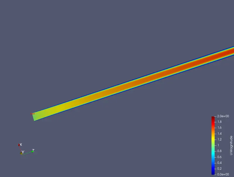
Cross Section
HYDRODYNAMIC LENGTH
Calculation
The formula to calcuate the hydrodynamic length is
`L_e=0.06R_eD`
`L_e=0.06 *2100*0.02=2.52m`
From the aboce calculation we can see that the fully developed flow in a pipe of dia 0.02m and a flow of reynolds number 2100 occures only after a length of 2.52m. Now let us validate it using the results from the simulation.
Velocity profile @ 0m=1m/s(Diameter vs Velocity)
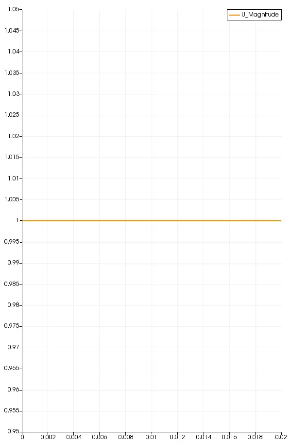
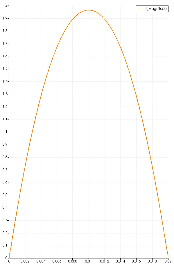
Velocity profile @2m=1.96m/s(Diameter vs Velocity)
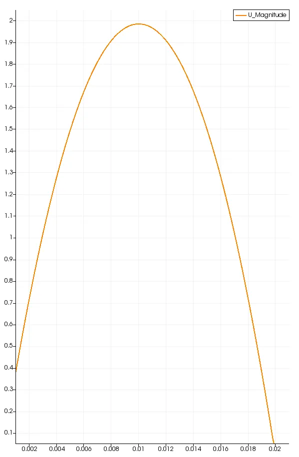
Velocity @ 2.6m=1.98m/s(Diameter vs Velocity)
Velocity @ 3m=1.98m/s(Diameter vs Velocity)
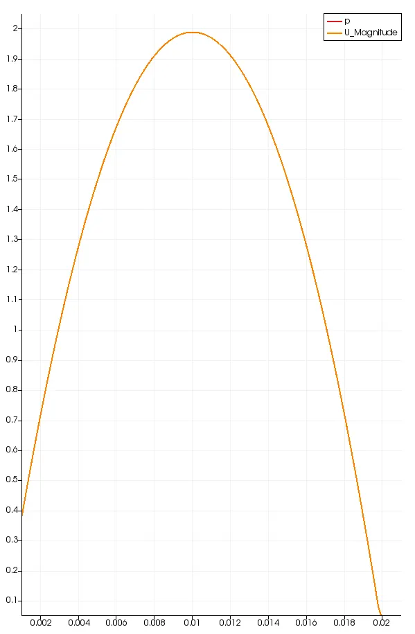
From the above images we can see that before the hydrodynamic length @2.5m the velocity of fluid is about 1.96m/s. After the entrance length for the two profiles i.e @2.6 m and 3m the maximum velocity 1.98m/s remains unchanged. Also the maximum velocity for the fully developed flow is 1.98m/s.
`V_max=2V_(avg)`
PRESSURE DROP (HAGEN POISEUILLE EQUATION)
We have to validate the pressure drop accross the pipe using the hagen-poiseuille's equation.
`P1-P2=(32muvL)/(D^2)`
where
P1-P2= Pressure Drop (N/m2)
`mu`= Dynamic Viscosity (ms/2)
`v`=Avergae velocity of fluid(m/s)
`L`=Length between pressure points(m)
`D`=Diameter of pipe(m)
`=(32 xx(9.52xx10^-3)xx0.4)/(0.02)^2`
`=304.64 Pa`
`=0.3m^2/s^2`
By the haigen poiseuille equation we can see that the knimetaic pressure is 0.3. We will now have to validate the pressure drop for the simulation.(The length is taken to be 0.4m as haigen poiseuille equation is valid only for fully developed flow).
Pressure Drop(Length vs Pressure Drop)
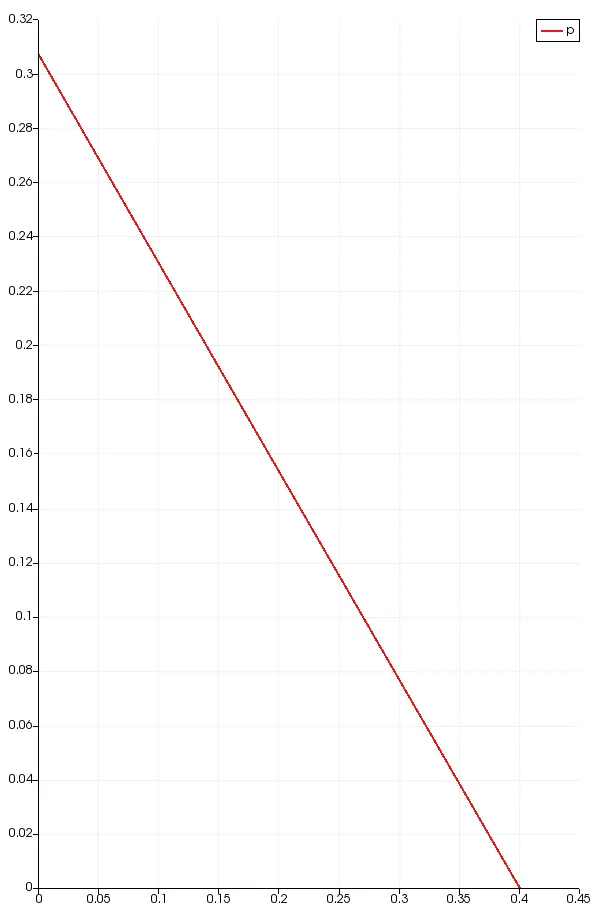
The pressure value obtained in openFoam is kinematic pressure in order to obtain the static pressure we will have to divide it by density..The pressure in the simulation is about 0.3 m2/s2 which is equal to the pressure drop obtained by the haigen poiseuille equation.
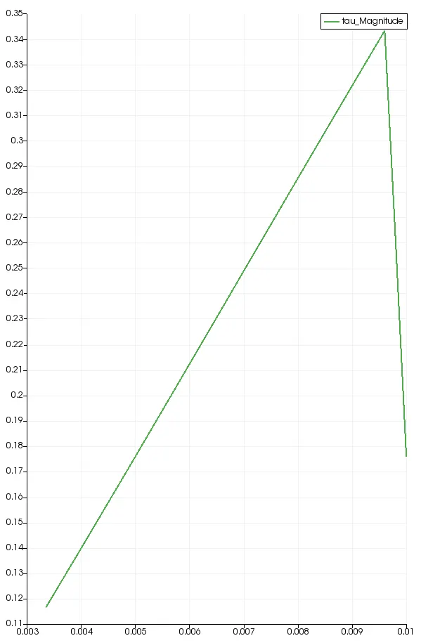
WALL SHEAR STRESS
The wall shear stress is the force generated by the walls of the pipe onto the fluid. The wall shear stress is directly propotional to the strain rate.
`tau prop ((du)/dx)`
`tau=mu((du)/dx)`
The wall shear stress is post processed from para view , by finding the gradient of velocity along the cross section of the pipe and then by multiplying the gradient with the dynamic viscosity.
(Radius vs wall shear)
MATLAB Code
We are also required to code in MATLAB to automatically generate a blockMeshDict file.
Main.m

degree=4;                               %degree of wedge
diameter=0.02;                          %pipe diameter
[x,y]=radian(degree,diameter);          %convert angle to radians
z=3;                                    %length of pipe
hexBlock=[0 4 1 0 3 5 2 3];
meshAlongX=50;
meshAlongY=1;
meshAlongZ=1000;
gradingX=1;
gradingY=1;
gradingZ=1;
patchName1='front';
patchName2='back';
patchName3='tankWall';
patchName4='inlet';
patchName5='outlet';
patchName6='axis';
type1='wedge';
type2=type1;
type3='wall';
type4='patch';
type5=type4;
type6='empty';
format long;
blockFace1=[0 1 2 3];
blockFace2=[0 3 5 4];
blockFace3=[1 4 5 2];
blockFace4=[0 4 1 0];
blockFace5=[3 5 2 3];
blockFace6=[0 3 3 0];
fprintf('/*-------------------------------*- C++ -*------------------------------*\\\n');
fprintf('  =========                    |\n');
fprintf('  \\\\      /  F ield          | OpenFOAM: The Open Source CFD Toolbox\n');
fprintf('   \\\\    /   O peration      | Website:  https:/openform.org\n');
fprintf('    \\\\  /    A nd            | Version 8\n');
fprintf('     \\\\/     M anuplation    |\n');
fprintf('/*----------------------------------------------------------------------*\\\n');
fprintf('FoamFile\n')
fprintf('{\n')
fprintf('   version       2.0\n');
fprintf('   format        ascii\n');
fprintf('   class         dictionary\n');
fprintf('   object        blockMeshDict\n');
fprintf('}\n');
fprintf('//* * * * * * * * * * * * * * * * * * * * * * * * * * * * * * * * * * * *//\n');
fprintf('convertToMeters 1;\n');
fprintf('vertices\n');
fprintf('(\n');
fprintf('(0 0 0)\n');
fprintf('(%.6f %.6f 0)\n',x,y);
fprintf('(%.6f %.6f %.0f)\n',x,y,z);
fprintf('(0 0 %d)\n',z);
fprintf('(%.6f -%.6f 0)\n',x,y);
fprintf('(%.6f %.6f %d)\n',x,y,z);
fprintf(');\n');
fprintf('blocks\n');
fprintf('(\n');
fprintf('hex(%s) (%d %d %d) simpleGrading (%d %d %d)\n',num2str(hexBlock),meshAlongX,meshAlongY,meshAlongZ,gradingX,gradingY,gradingZ);
fprintf(');\n');
fprintf('edges\n');
fprintf('(\n');
fprintf(');\n');
fprintf('boundary\n');
fprintf('(\n');
fprintf('   %s\n',patchName1);
fprintf('   {\n');
fprintf('      type %s;\n',type1);
fprintf('      faces\n');
fprintf('      (\n');
fprintf('      (%s)\n',num2str(blockFace1));
fprintf('      );\n');
fprintf('   }\n');

fprintf('   %s\n',patchName2);
fprintf('   {\n');
fprintf('      type %s;\n',type2);
fprintf('      faces\n');
fprintf('      (\n');
fprintf('      (%s)\n',num2str(blockFace2));
fprintf('      );\n');
fprintf('   }\n');

fprintf('   %s\n',patchName3);
fprintf('   {\n');
fprintf('      type %s;\n',type3);
fprintf('      faces\n');
fprintf('      (\n');
fprintf('      (%s)\n',num2str(blockFace3));
fprintf('      );\n');
fprintf('   }\n');

fprintf('   %s\n',patchName4);
fprintf('   {\n');
fprintf('      type %s;\n',type4);
fprintf('      faces\n');
fprintf('      (\n');
fprintf('       (%s)\n',num2str(blockFace4));
fprintf('      );\n');
fprintf('   }\n');

fprintf('   %s\n',patchName5);
fprintf('   {\n');
fprintf('      type %s;\n',type5);
fprintf('      faces\n');
fprintf('      (\n');
fprintf('      (%s)\n',num2str(blockFace5));
fprintf('      );\n');
fprintf('   }\n');

fprintf('   %s\n',patchName6);
fprintf('   {\n');
fprintf('      type %s;\n',type6);
fprintf('      faces\n');
fprintf('      (\n');
fprintf('      (%s)\n',num2str(blockFace6));
fprintf('      );\n');
fprintf('   }');
fprintf(');\n');
fprintf('mergePatchPairs\n');
fprintf('(\n');
fprintf(')\n');
fprintf('//************************************************************************//')


radian.m

function [x,y]=radian(angle,diameter)
x=(diameter/2)*sin((angle*pi)/180);
y=(diameter/2)*cos((angle*pi)/180);
end
Inputs:
1.Diameter of pipe
2.Length of pipe
3.Angle of wedge
4.Hex block
5.Mesh alon X,Y and Z
6.Grading factor
7.Patch Names
8.Types of patch
9.Block faces
Output:
blockMeshDict file is generated.
CONCLUSION
1.The hydrodunamic length was found out to be 2.52m through calculation and validated through the simulation as the velocity never changed from 1.98m/s after the entrance length ,proving that the flow is fully developed after the hydrdynamic length.
2.The fully developed flow velocity profile has been validated with the analytical one.
3.The pressure drop calculated from the haigen poiseuille equation was found out to be 0.3 m^2/s^2 and was validated through the values obtained from the simulation.
4.The wall shear stress has been validated for the fully developed flow.
5.A MATLAB code for automatic generation of blockMeshDict file has been coded.