Week 11 - Project - A pillar Design with Master Section
AIM
Points to ensure:
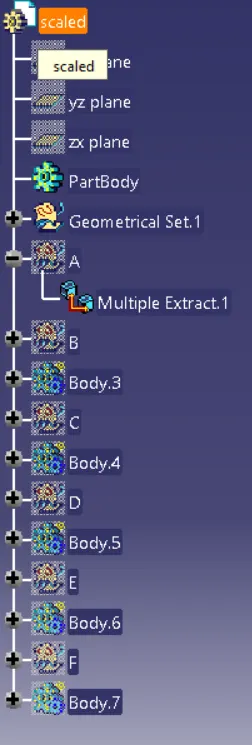
In Tree Structure
- Ensure using the surface command.
- Use closed body command to create the solids
- Rename the geometrical set properly.
Output Required in a ppt :
- Picture of the sketches with Sketch solving status’s geometry tab
- Picture of the Detailed tree structure.
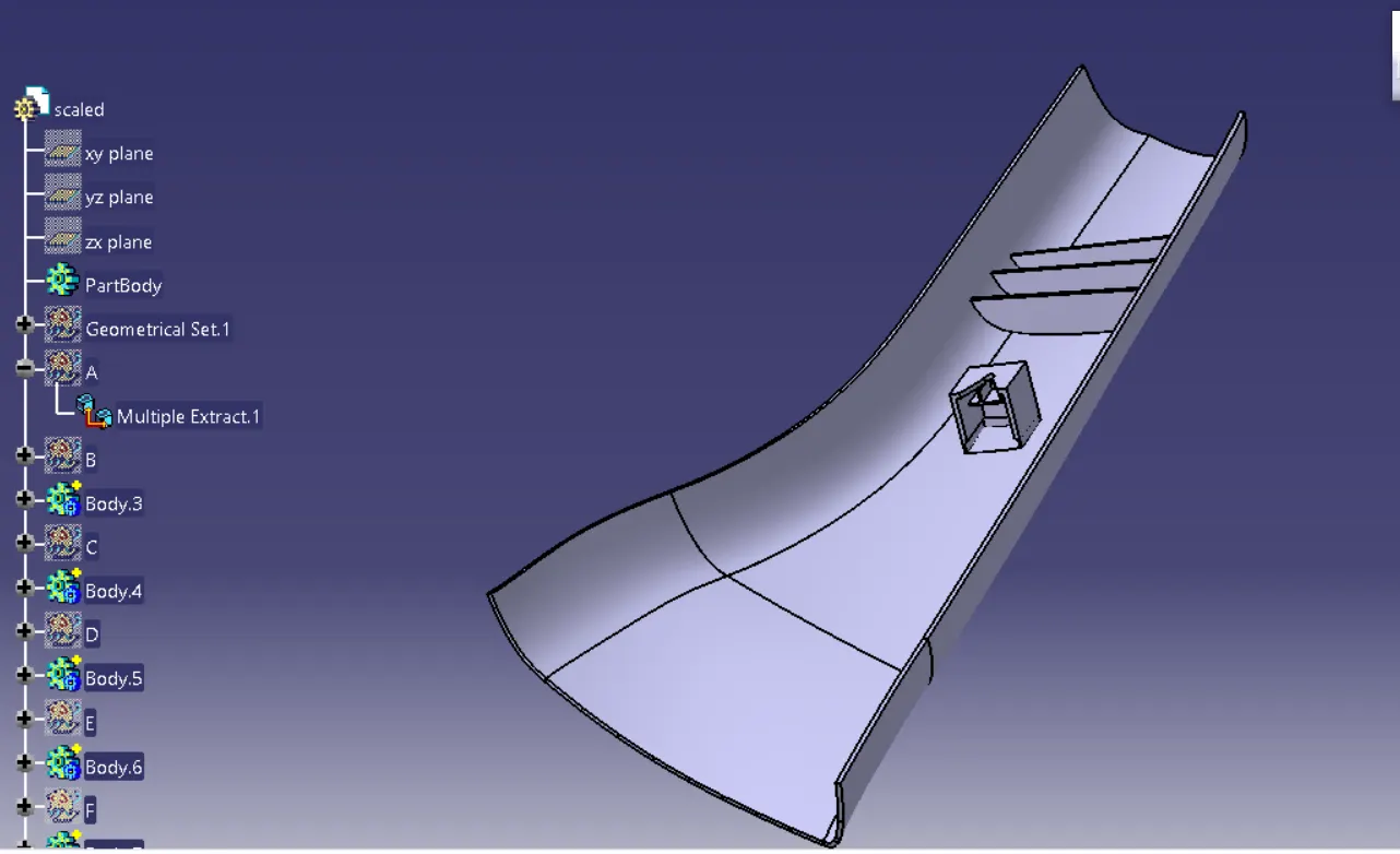
- Picture of the 3D CAD
- Create closed body
- Create a tooling axis and follow design rules.
- Follow the Master section to create a flange
- Follow the master section for thickness and to create the Closed volume.
- Follow the master section to create Attachment features
- The thickness of the Plastic to be 2.5 mmCLASS A SURFACE:
Class-A (or 'Strak') is a term used in specifically in automotive design. It describes the final production Class data for the aesthetic parts of the car. The term 'Class A' is often misunderstood, but it's generally seen as the 'Holy Grail' of Class modeling.
- Since we copy the Class A from the original Class A, then create separate geometric set then paste it. Then join the Class A.
TOOLING AXIS
- Now we create tooling axis for the Class A. First a create axis system for where we want, then we create intersect based on the axis system.
- Extract the bottom surface and insert point on a surface then create lind based on a point.
CLASS A SURFACE:
The Class A Surface is given with the master section.
CLASS B SURFACE:
- Now create a class B surface.
- In class B, first create base of class B from class A. Insert geometrical set define as class B, that is base of class B.
- Use extract command and extract a base from class A. Then use untrim tool get full body of a base. Next use extrapolate tool extended a base , then offset of 2.5 mm.
CLASS C:
- Class C is nothing but its connecting part of Class A & B.
- Unhide the class A and take boundary of its and now boundary select the all corner of a class A and use sweep commends the we get a class c of boundary in Class A.
- Then trim it finally get class C.
CLOSE BODY:
- Go to the part body workbench then use close boby tool and finally get close body of base bracket.
DOG HOUSE:
- Create sketch for a dog house, and pad it.
- Then pad this sketch, now shell the pad with 2.5 mm.
RIBS:
- Now create a ribs is inside a dog house, create a sketch for a ribs,use master section.
- Then pad this sketch . Next use add with dog house, get a ribs for the body
CLASS A DRAFT ANASLYSIS:
CLASS B:
CLASS C:
CLASS A AND C JOIN:
CLOSED SURFACE:
DRAFT ANALYSIS OF CLOSED SURFACE:
DOG HOUSE:
SKETCHES:
DRAFT ANALYSIS:
Conclusion
•Created Tooling axis
•Created Class B and Class C surface from provided Class A surface.
•Created solid part out of surface modelling.
•Created engineering features from the master section provided.
•Draft analysis of Class A surface and final part is also done.