Week 11 - Project - A pillar Design with Master Section
OBJECTIVES:
- Creation of Tooling axis with appropriate draft analysis for given A class surface and master section.
- Creation of B class and C Class surfaces for creating a solid component.
- Creation of attachment features like Dog house.
- Performing final draft analysis and creating final product.
CLASS A SURFACE:
- Visible surface and aesthetic look.
- Surface with textures.
- Surfaces provided by customer(OEM).
- Don't have any features like(rib, snap, bosses, etc) on class A surface.
- Class A surface is made from scanned data with different software like alias etc.
- Surfaces which are having CURVATURE CONTINUITY IS CALLED class-A.
MAIN TOOLING AXIS:
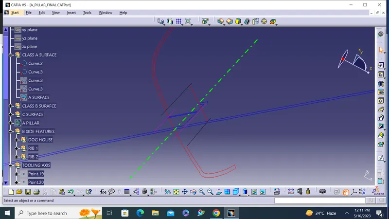
Tooling direction is main consideration for plastic part and mold parts because it defines movement of mold part and possibility of plastic part to come-out from mold part (Core and Cavity).
- In Molding machine arrangement is given to open the mold along a direction which is known as Tooling Direction.
- In other words. The mold is built from two separate halves (Core and Cavity) and tooling direction basically define the direction of mold pulls apart.
- Tooling direction is known as primary direction.
- One more new metohd to find the tooling direction is by using the CG(Centre of gravity) part and crete line centre point and one flat surface.
- But in A pillar design we have an Master Section based on that we considered the tooling direction.
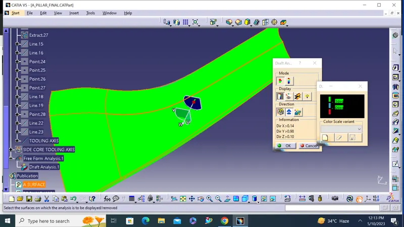
CLASS A SURFACE DRAFT ANALYSIS:
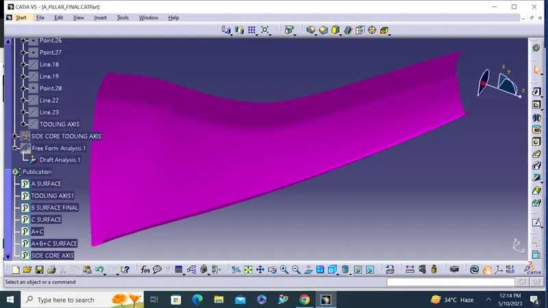
CLASS B SURFACE
- Invisible Surfaces.
- Surface mostly don't have textures.
- Surface needs to be created according to the class-A surface.
- Having all features(Rib,boss,snap etc) in B-side surface only.
- Surfaces which is having TANGENT CONTINUITY IS CALLED class-B.
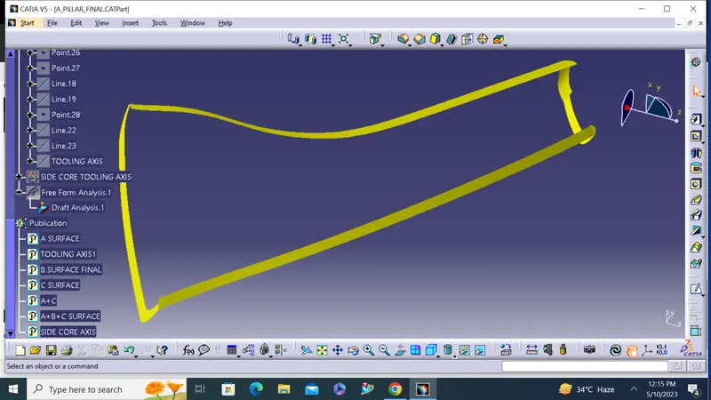
CLASS C SURFACE:
- Extract tool is used to create the boundary lines separately on side edges of class A surface
- Sweep comment is used to create surface C class for separate edges from given master section reference.
- Finally merge all sweep surface to get class C surface.
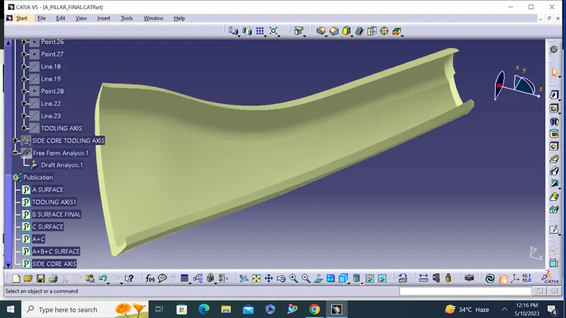
A+C SURFACE:
AC+B SURFACE:
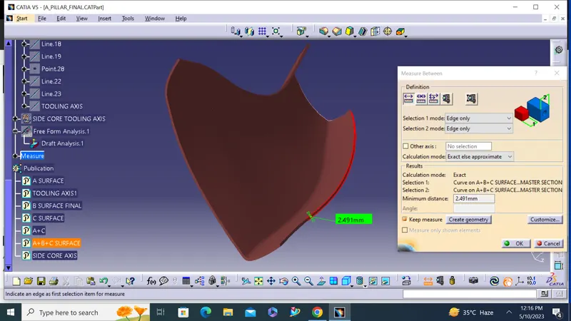
A PILLAR SOLID PART:
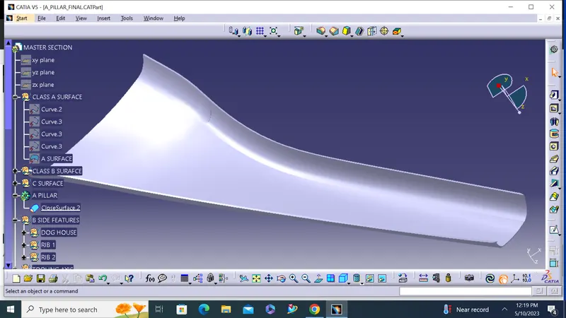
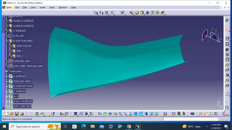
A PILLAR DRAFT ANALYSIS:
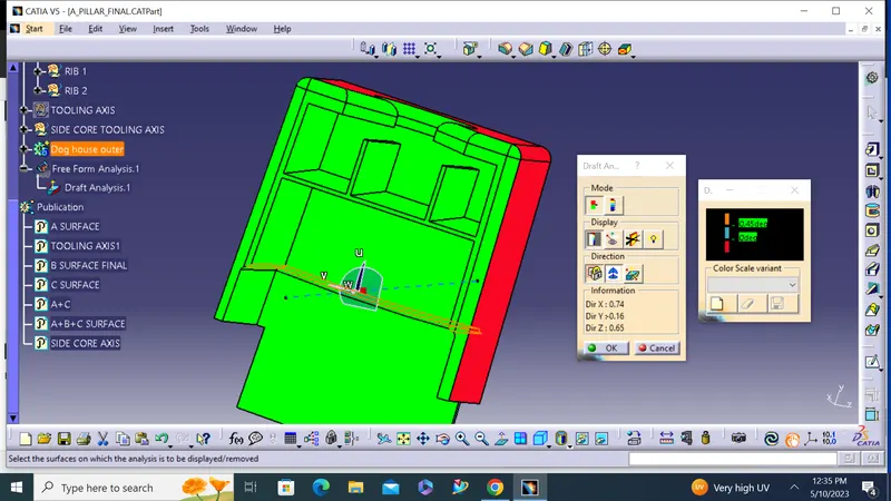
Draft analysis:
- First the material mode is selected in customize view.
- Now click on the compass tab and align it with tooling axis .
- Now click on the lock .
- click on the surface .
- Surface colour shows green , which mean that the it has more than 3 degree angle , which is good for manufacturing .
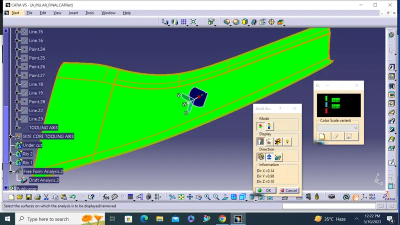
DOG HOUSE:
Main functions of dog house.
- To eliminate the sink marks
- To lift the bosses for hight
- To give outside bosses from B surface
Design rule:
- Its wall thickness at the intersection of the part should be 40 % or less than the main wall.
- The height should be between 3-6 mm.
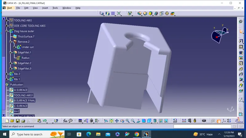
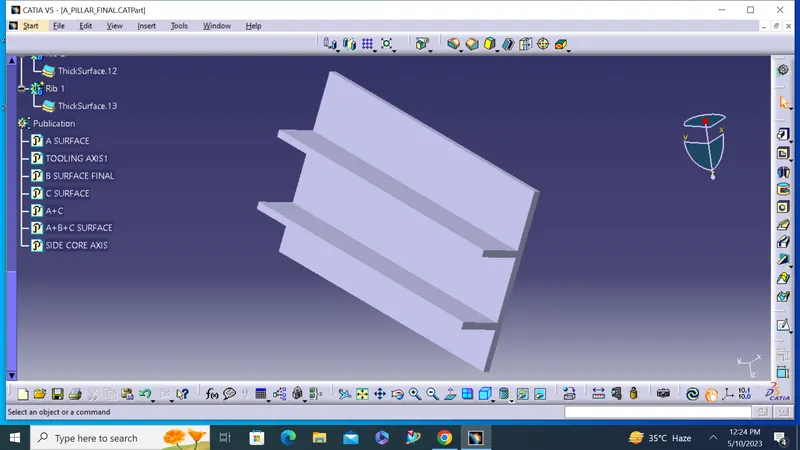
RIBS:
Ribs are indispensable functional structures on many plastic parts. It can effectively improve the rigidity and strength of plastic parts like the H beam. By using ribs, it is not necessary to greatly increase the wall thickness of the plastic parts, and ribs are not undercut structures like the H beam whose structure will be difficult to make for plastic injection molding. So ribs work well for plastic parts that are subject to pressure, torsion and bending. Ribs can also act as internal flow passages to aid in the plastic melt filling flow, which is of great help to the formation of complex and large plastic parts.
B SIDE FEATURES:
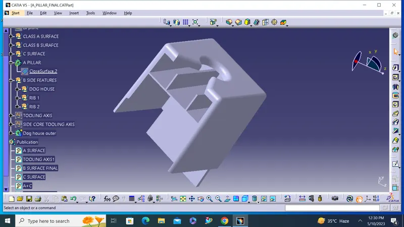
B SIDE FEATURE WITH SIDE CORE TOOLING AXIS:
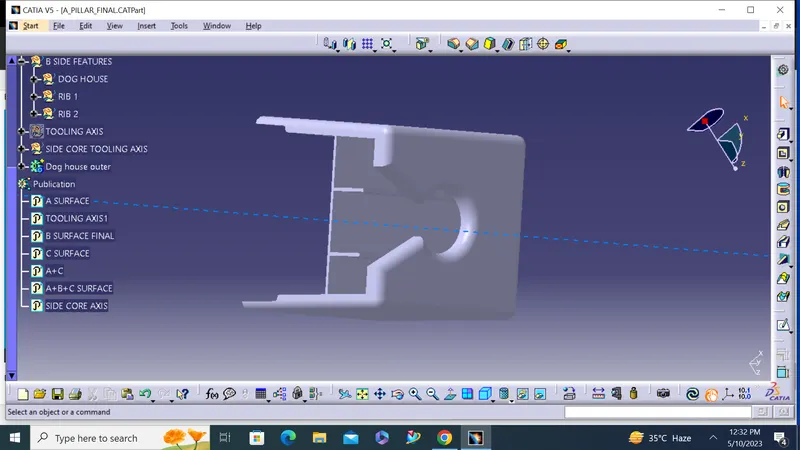
- The side core axis is created normal to the surface of dog house.
- Dog house inner walls and all other rib draft analysis is cleared using side core axis.
B SIDE FEATURE DRAFT ANALYSIS:
A PILLAR WITH B SIDE FEATURES:
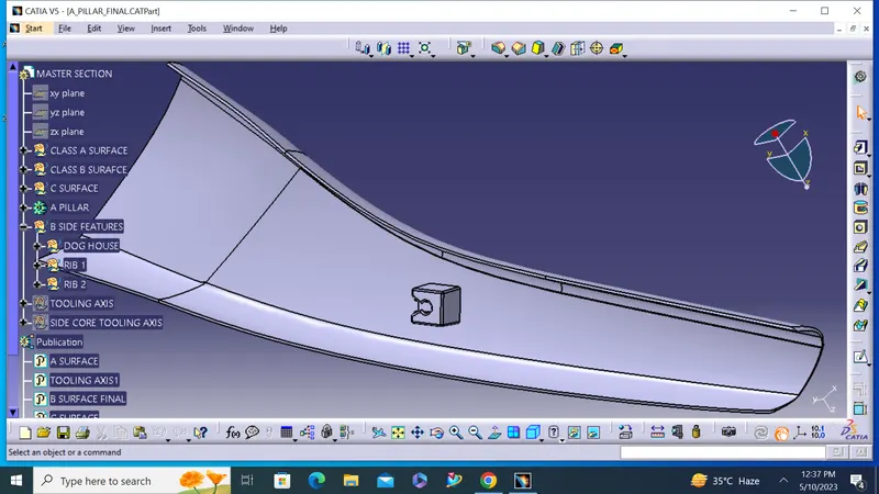
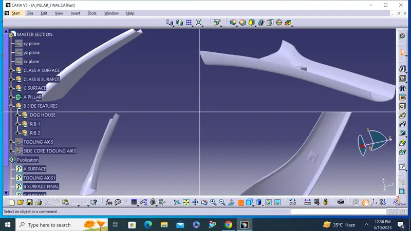
VIEWS:
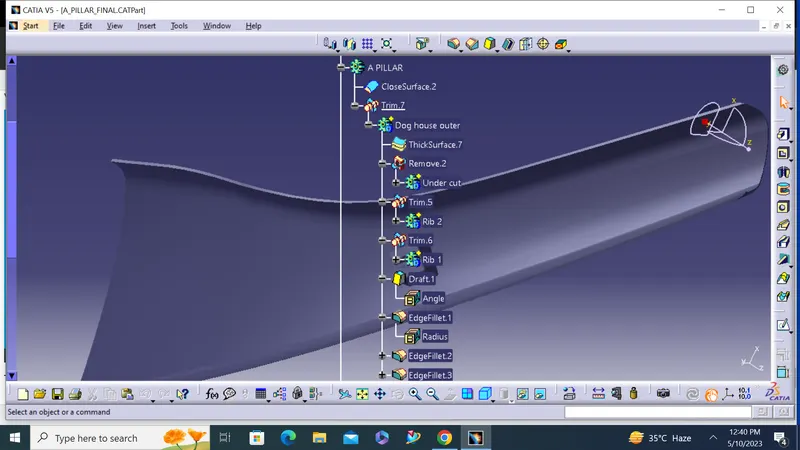
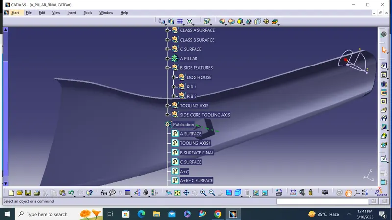
TREE STRUCTURE: