Week 11 - Final project
Aim: To develop an automobile door trim using CATIA and provide engineering components for attachment purposes.
Theory:-
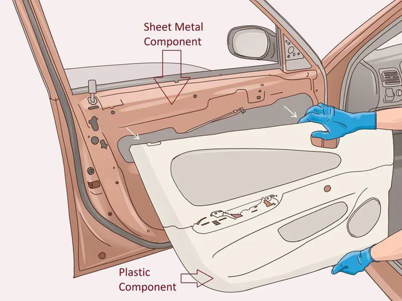
Automobile Door Trim: An interior component attached to the inner side of the door. This product does more than merely improve the appearance of the vehicle interior. Rather, it is a vital module component that creates a more comfortable interior by providing a variety of accouterments and functions.
Main Components of Automobile Door Trim
> Armrest
> Map Pocket
> Bottle Holder
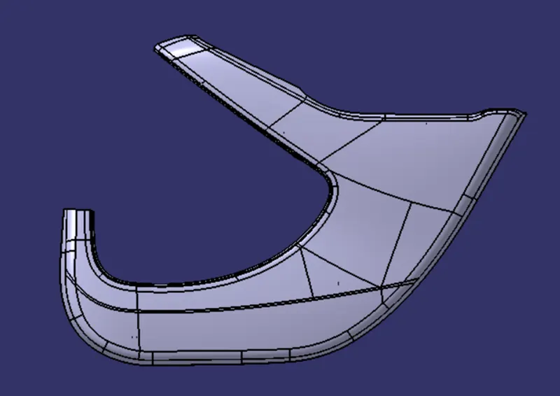
> Lower Substrate
Arm Rest:-
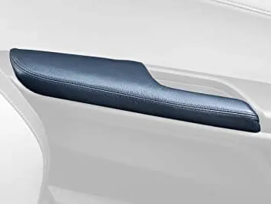
An armrest offers the possibility of comfortably positioning your hand when driving on a motorway or standing in traffic.
Depending on the equipment of an individual vehicle, it can also combine the functions of the control console of the vehicle's electrical systems and the practical storage compartment.
Map Pocket:-
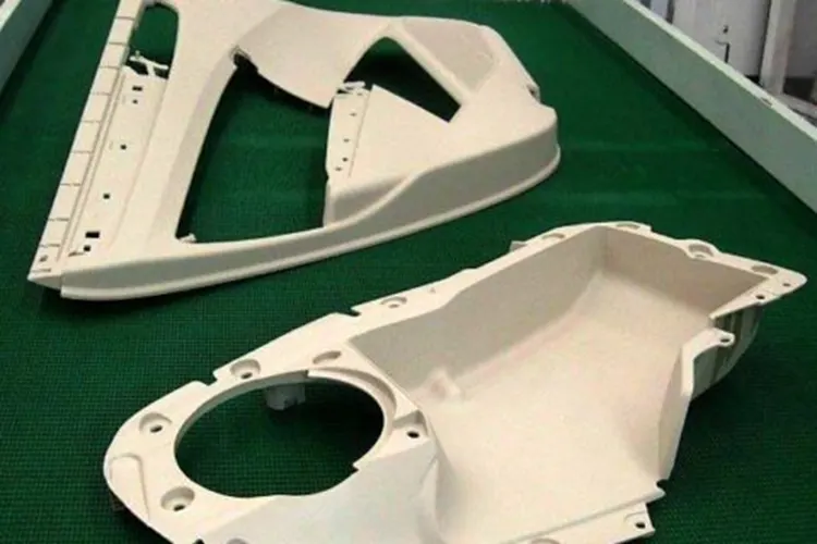
It is a functional component essentially used to provide placement area for the Automobile Sound system, depending upon the vehicle and its structure the utility may defer and the size of the music system may also vary the size of this component.
Bottle Holder:-
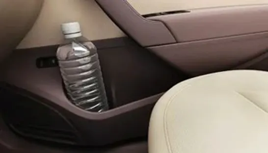
As the name suggests, the bottle holder is a component used to provide a storage area to store bottle and the size vary from the model of the car.
Lower Substrate: -
Designing Aspect: -
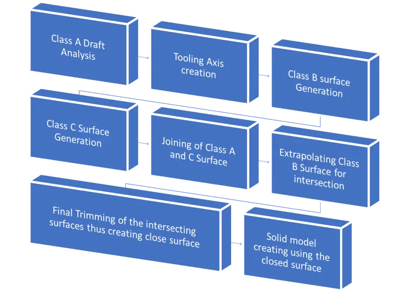
#Design Flow Followed to develop the parts are: -
Design Specification: -
Surface Thickness: 2.5 mm
Draft Provided on the main body: 3 deg
The draft provided on heat Stakes: 0.5 deg
1. Part Creation: -
A) Arm Rest: -
Tool Axis Creation: -
In Molding, machine arrangement is given to open the mold along a direction which is known as Tooling Direction.
1. Likewise in our model, we first create a tooling axis from the pocket side walls:-
2. Now we create the bisecting line from the two lines we have created now.
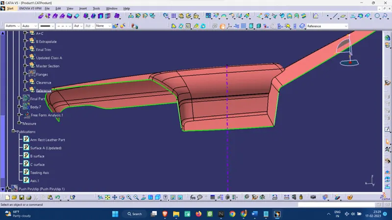
3. To check if this Bisecting Line will actually work as a tooling axis we see the top view of the line to see if all the 3 surfaces in the pocket can be seen or not.
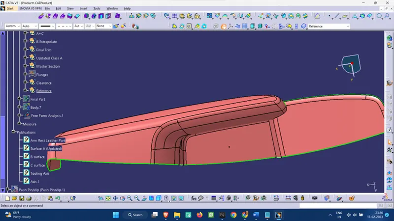
Draft analysis:-
Standard Measurements:
Model Thickness: 2.5 mm
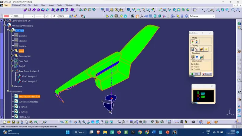
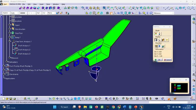
The minimum Draft angle provided: 3 deg angle
Class A surface Draft analysis:-
Final Body draft analysis:-
Different surfaces:-
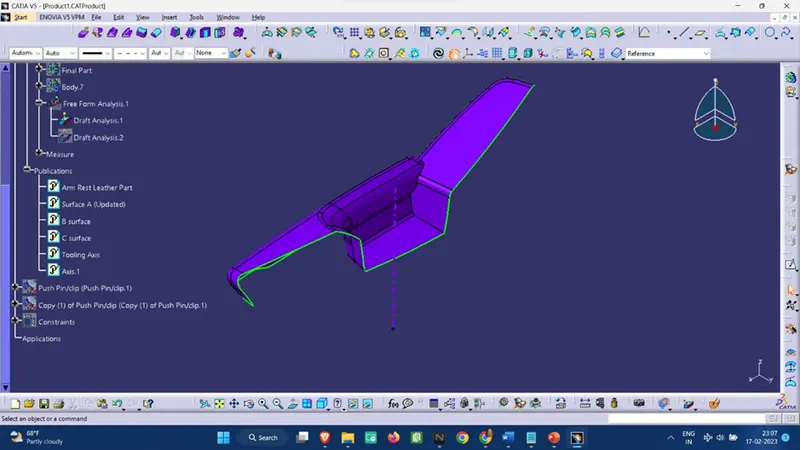
Class A surface:
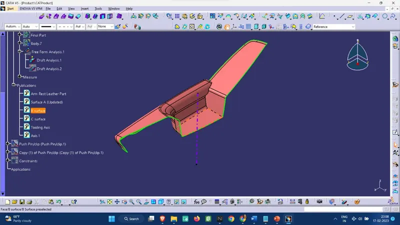
Class B surface:
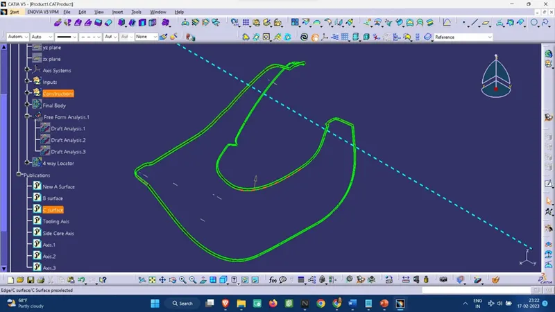
Class C surface:
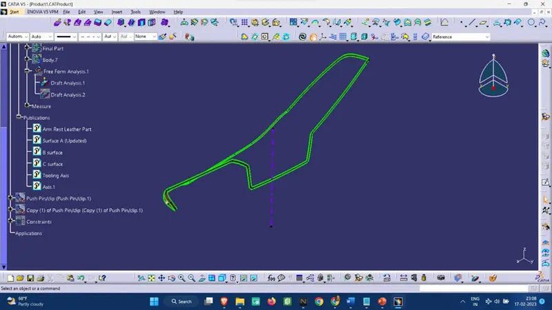
Flange Created via Master Section:-
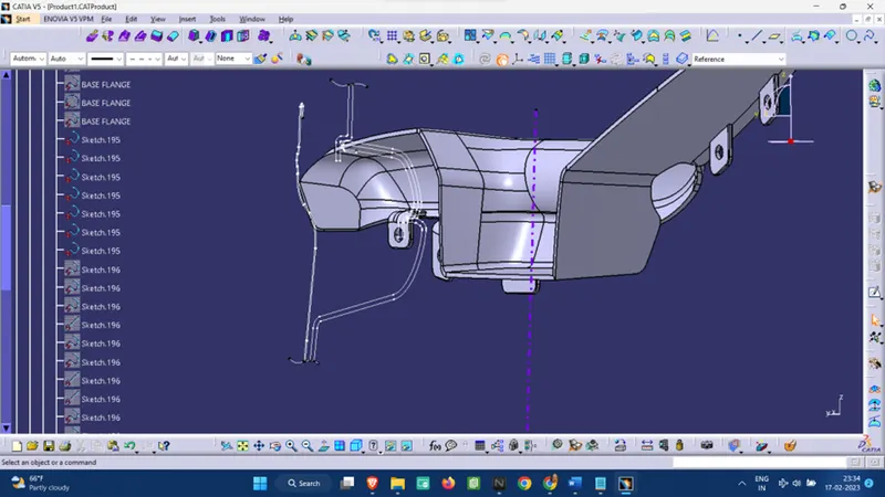
B) Map Pocket :-
Tool Axis Creation: -
In our model, we first create a tooling axis from a flat surface. Here we first orient the model in the Y direction and extract a flat surface. Then we take a point at the body centre and draw a line in the Y direction.
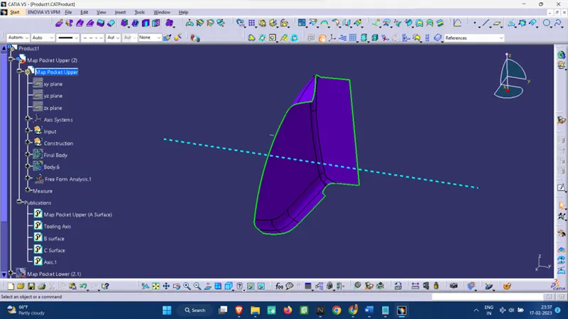
Note: To create a tooling axis using one of the 2 mostly used methods, i.e
> From a large circular contour
> From a large flat surface.
3. Now we move on to make the B Surface:-
As there are different components in the body, hence it is recommended that one should segregate and split the parts for easy surface generation and also cascade the components in an orderly manner.
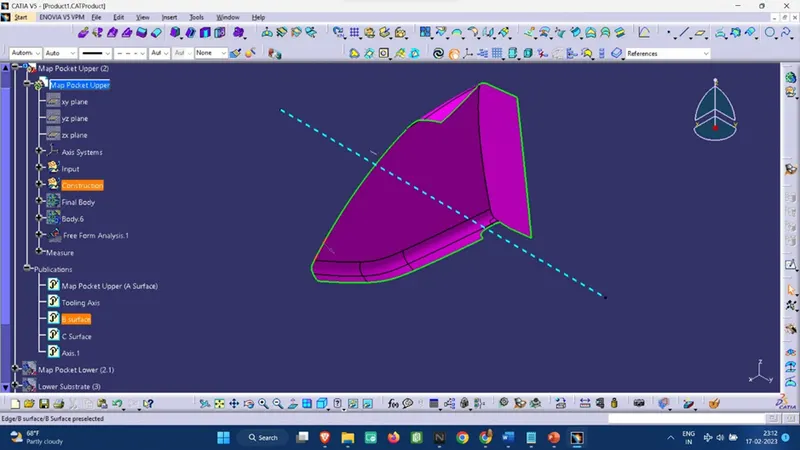
> For Surface Generation we first offset the Class A Surface and then we use the ‘Join’ and ‘Sub-element to remove’ commands to fill any holes and gaps as from offsetting a large surface, some of the fillets may not be generated.
> Now we measure the fillet from the Class A surface and as surface B is inside the Class A surface, hence we will add the thickness value along with the fillet value.
Note: For areas that are too intricate, then we may give the exact value of the fillet or give a nominal value to the fillets for smooth surface generation.
> Now we move to make the C surface, where we first make a boundary at the edge and use the ‘Sweep command’ for surface generation.
Note: One should always remind that B Surface should not be generated above the Class A surface as the Class A surface holds the aesthetic value and comes in direct contact with the consumer, therefore no changes should be made to the class A surface.
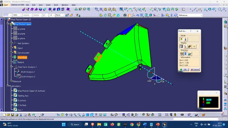
Draft analysis:-
Standard Measurements:
Model Thickness: 2.5 mm
The minimum Draft angle provided: 3 deg angle
Class A surface Draft analysis:-
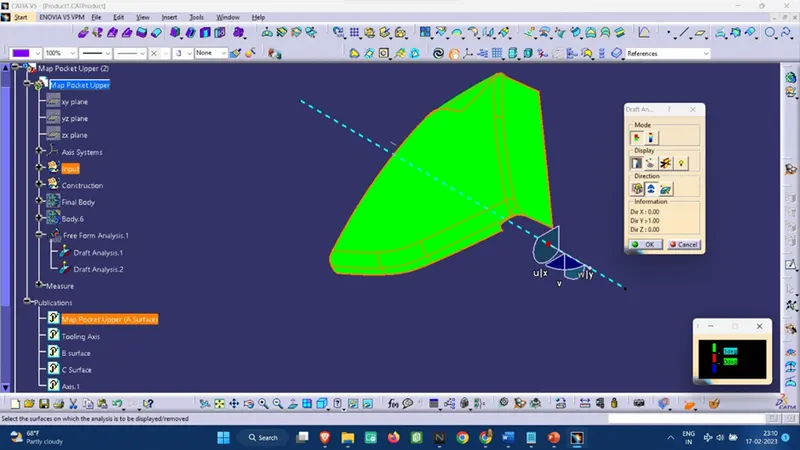
Final Body draft analysis: -
Different surfaces:-
Class A surface:
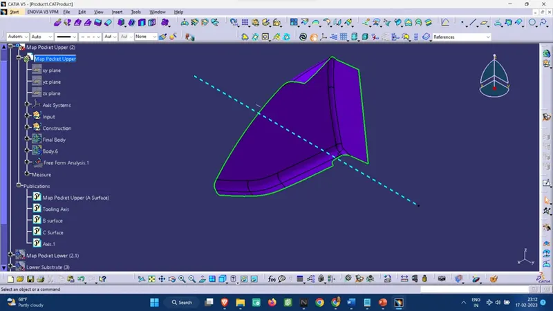
Class B surface:
Class C surface:
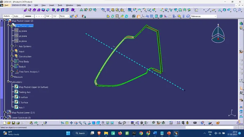
Note: To generate the Class C Surface, we have used “Sweep Command” along with the “Reference to the surface” option at 93 degrees (3 Deg as Draft angle), as in this part the C surface is at a right angle with the Draft axis.
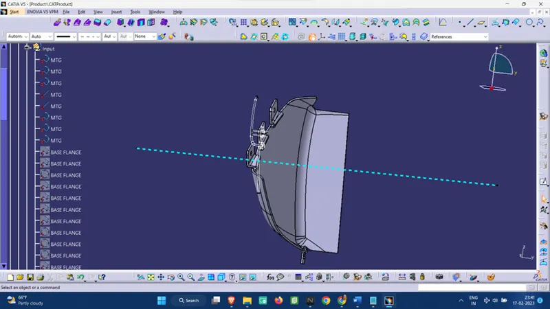
Flanges are Created Via Master Section:-
C) Bottle Holder:-
Tool Axis Creation: -
In our model, we first create a tooling axis from a flat surface. Here we first orient the model in the Y direction and extract a flat surface. Then we take a point at the body centre and draw a line in the Y direction.
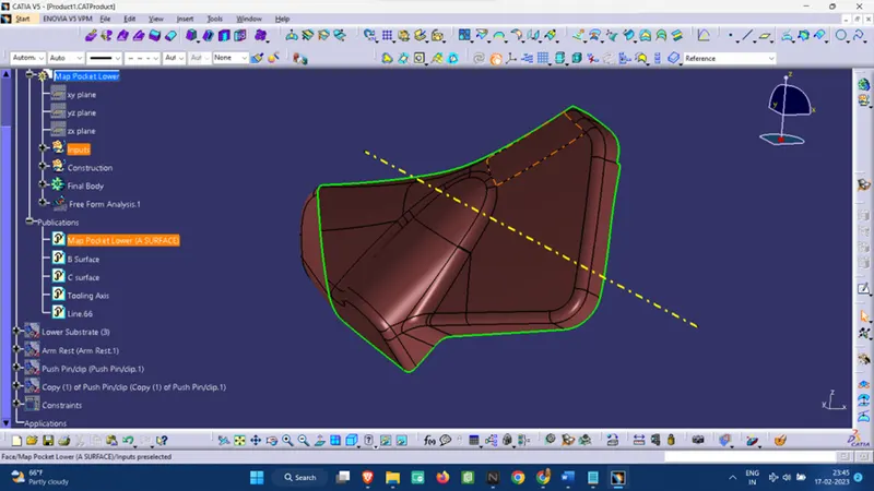
3. Now we move on to make the B Surface:-
As there are different components in the body, hence it is recommended that one should segregate and split the parts for easy surface generation and also cascade the components in an orderly manner.
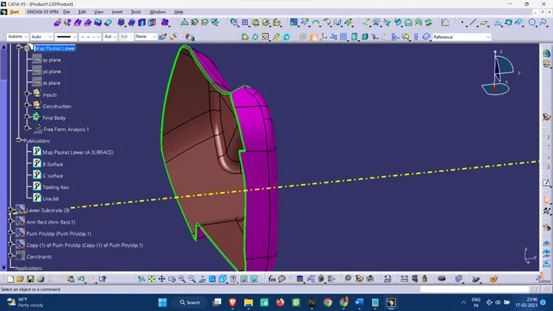
> For Surface Generation we first offset the Class A Surface and then we use the ‘Join’ and ‘Sub-element to remove’ commands to fill any holes and gaps as from offsetting a large surface, some of the fillets may not be generated.
> Now we measure the fillet from the Class A surface and as surface B is inside the Class A surface, hence we will add the thickness value along with the fillet value.
Note: For areas that are too intricate, then we may give the exact value of the fillet or give a nominal value to the fillets for smooth surface generation.
> Now we move to make the C surface, where we first make a boundary at the edge and use the ‘Sweep command’ for surface generation.
Draft analysis:-
Standard Measurements:
Model Thickness: 2.5 mm
The minimum Draft angle provided: 3 deg angle
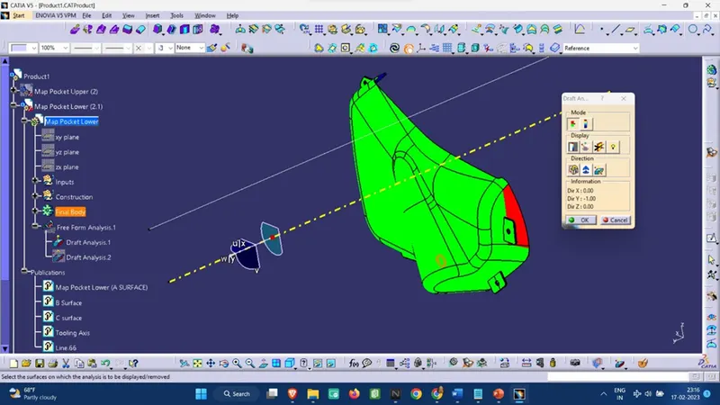
Class A surface Draft analysis:-
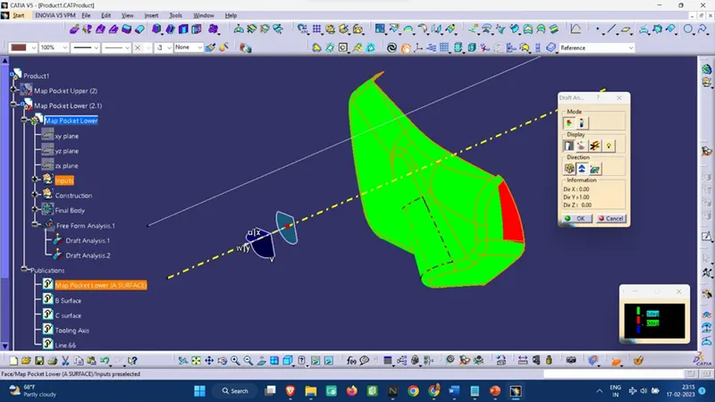
Note: As the reference, A class surface that was provided in the question does not have a 3 deg draft on the side panels, thus we can see the red part on the draft analysis.
Final Body draft analysis: -
Different surfaces:-
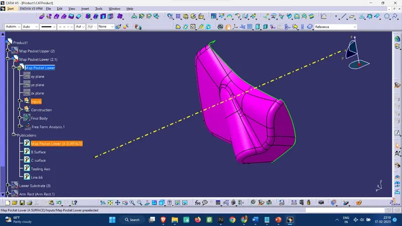
Class A surface:
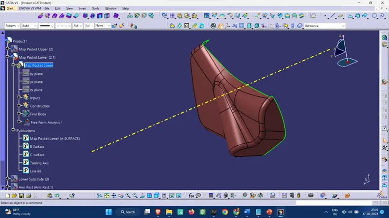
Class B surface:
Class C surface:
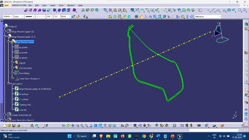
Note: To generate the Class C Surface, we have used “Sweep Command” along with the “Reference to the surface” option at 93 degrees (3 Deg as Draft angle), as in this part the C surface is at a right angle with the Draft axis.
Flanges are Created by taking a plane and using Sweep Command:-
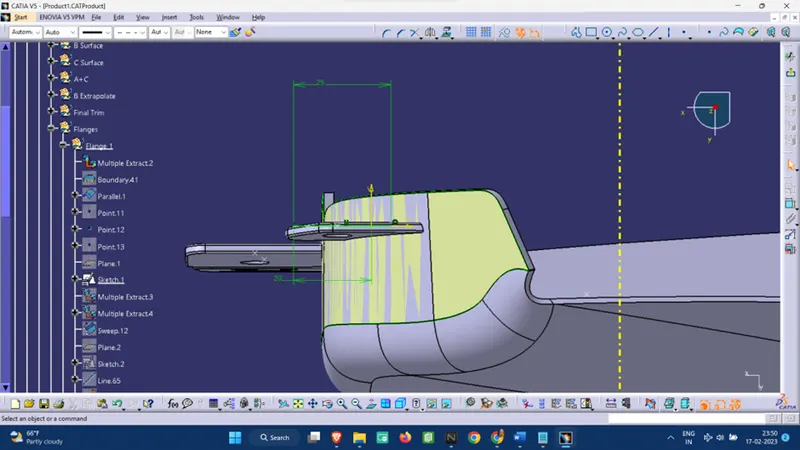
Note: To lower the cost of production, one may choose to make the flange in a Z type manner which removes the need of the side core for production.
D) Lower Substrate:-
Tool Axis Creation: -
In our model, we first create a tooling axis from a flat surface. Here we first orient the model in the Y direction and extract a flat surface. Then we take a point at the body center and draw a line in the Y direction.
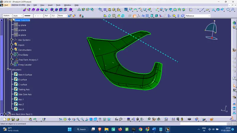
3. Now we move on to make the B Surface:-
As there are different components in the body, hence it is recommended that one should segregate and split the parts for easy surface generation and also cascade the components in an orderly manner.
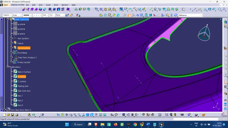
> For Surface Generation we first offset the Class A Surface and then we use the ‘Join’ and ‘Sub-element to remove’ commands to fill any holes and gaps as from offsetting a large surface, some of the fillets may not be generated.
> Now we measure the fillet from the Class A surface and as surface B is inside the Class A surface, hence we will add the thickness value along with the fillet value.
> Now we move to make the C surface, where we first make a boundary at the edge and use the ‘Sweep command’ for surface generation.
4. Dog House Creation: -
> At first we need to have a sketch of the boundary of the dog house for which we can do the following:-
> Extract a plane surface
> Create a plane surface using the “Plane” command with the normal to curve command.
> Now we create a point for the position sketch.
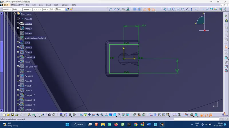
> Now to generate the sidewalls we can do the following:-
> Use the Sweep command using the tooling axis
> Use the Extrude command and later provide the draft.
> After creating the side walls with Sweep at 1.5 deg draft angle, we then thicken the surface
> Now we provide a 0.5 deg draft to the inner surfaces.
> We need to create a side core axis for the internal draft of the dog house.
> Then we create the Undercut using an offset command and Split command.
> Now we Union trim the excess surface of the Dog house from the main body.
Standard Measurements:
Model Thickness: 2.5 mm
The minimum Draft angle provided: 3 deg angle (Main body)
1.5 deg angle (Dog House outer walls)
0.5 deg angle (Dog house inner surface)
Calculations:-
Wall Thickness of the dog house = 2 mm
Wall Thickness of the under cut = 0.4*2.5=1 mm
Draft analysis:-
Standard Measurements:
Model Thickness: 2.5 mm
The minimum Draft angle provided: 3 deg angle
Class A surface Draft analysis:-
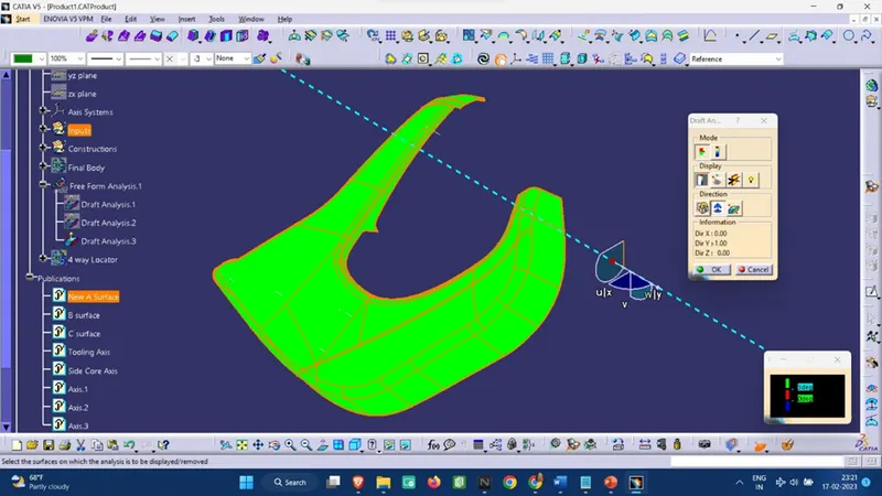
Final Body draft analysis: -
a) At 3 mm draft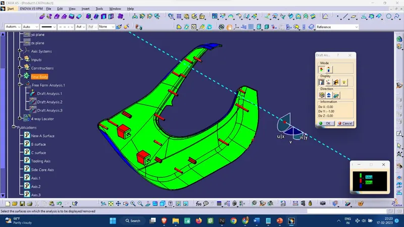
At 0.45 mm Draft:-
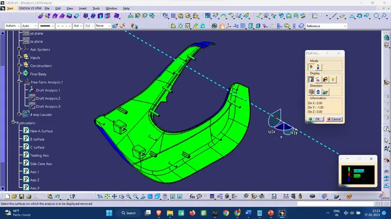
Different surfaces:-
Class A surface:
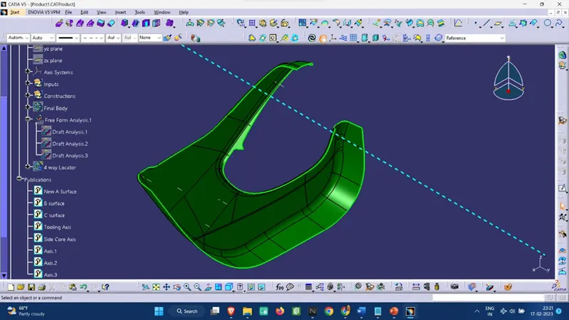
Class B surface:
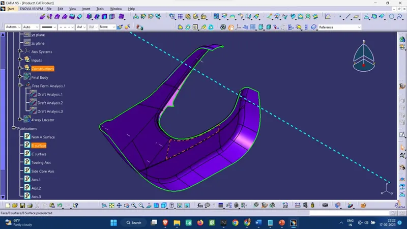
Class C surface:
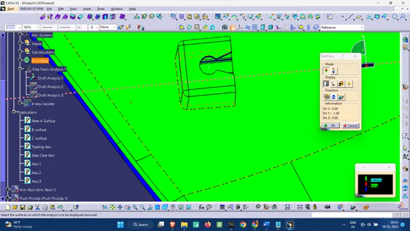
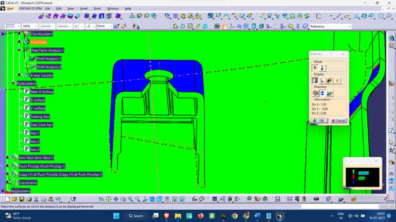
Draft analysis of the Dog house:-
Draft analysis with the Tooling Axis:- (Outside)
Draft Analysis with the side Core axis:- (Pink line is the side core axis for inside draft)
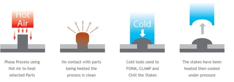
Heat Staking: It is a method of joining two or more parts, where at least one is made out of plastic. The bond is made by partially de-forming the plastic part to fix the other.
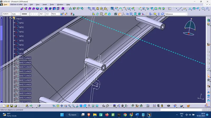
Heat stake are Created with reference to the master section:-
Assembling Strategy:-
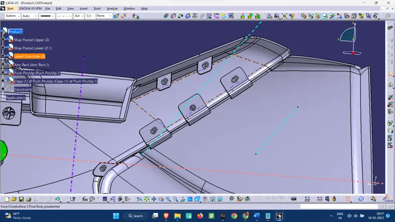
To assemble all the parts of the Door trim of the Automobile we have provided the below Engineering features:-
Push Pin: To fix one panel with another panel with holes for Assembling Plastic components.
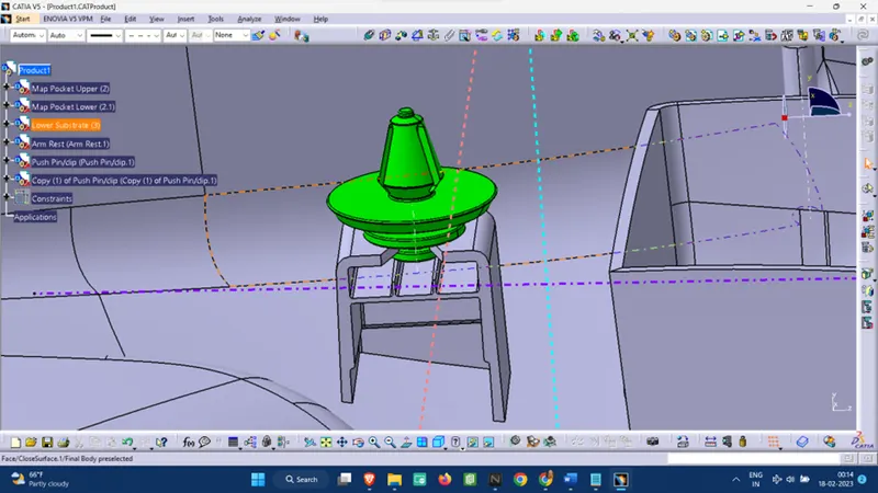
Four-Way Locators: To constrain the rotatory motion of the body.
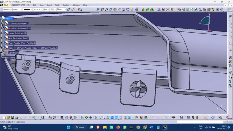
Heat Stakes: These can be used for the permanent joining purpose by first placing the joining component in place and then using a heat gun to seal the joint.
Conclusion: -
Draft analysis is a very essential tool for manufacturing a plastic product using Core and cavity manufacturing techniques, hence draft angle should always be provided appropriately.
Support features are to be added by applying all the design rules since it will help the final part to gain the sufficient support it needs during the injection molding process.