Week 11 - Final project
OBJECTIVE
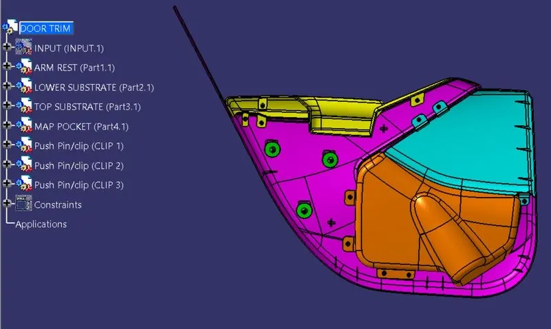
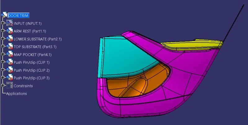
The Objective of the project is to design the vehicle interior door trim panel by using CATIA V5 With given class-A surfaces along with the master seection and engineering feature as per the guidline.
INTRODUCTION
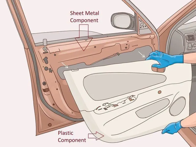
Door panels is an interface between the interior of the car and the inner workings of the door, and between vehicle occupants and the door. Door panel consist of many parts such as arm rest, lower substrat, top substrat, map pocket. This parts should be designed in such a manner that it can bear and stay in position while external forces are applied onto it.
PROCEDURE
1- Lower Substrat Design
2- Arm Rest Design
3- Top Substrat Design
4- Map Pocket Design
LOWER SUBSTRAT DESIGN
PROCEDURE
- Creation of Tooling Axis
- Creation of Class B surface
- Creation of Class C Surface
- Perform draft analysis
- Create Engineering Feature
CREATION OF TOOLING AXIS
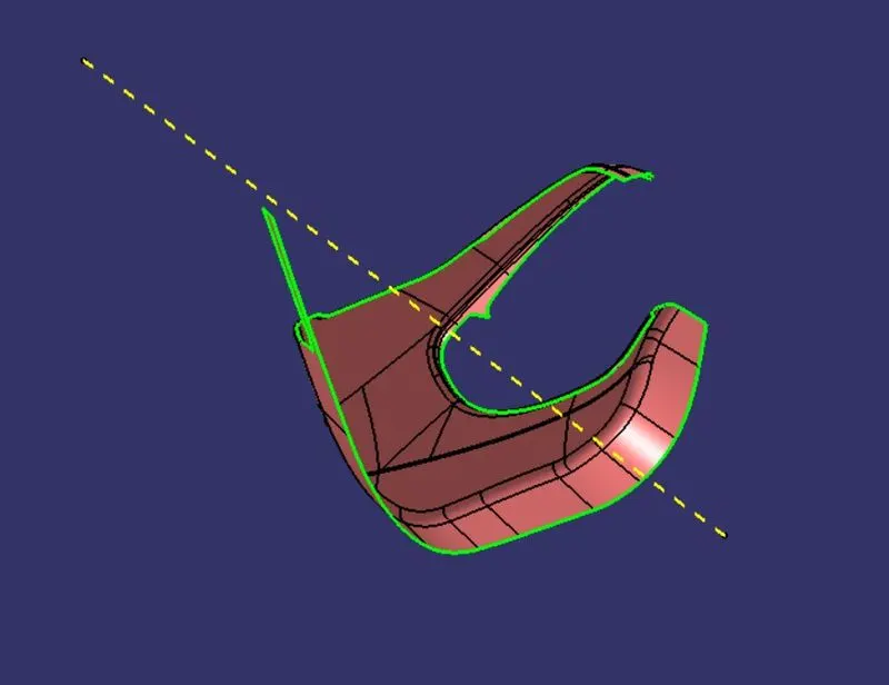
Tooling axis is the direction in which the mold and cavity opens and closes in the injection molding operation.We have created a point on the edge of the part and created a line, that line is our Tooling axis.
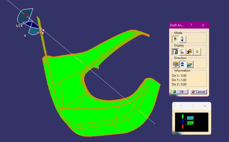
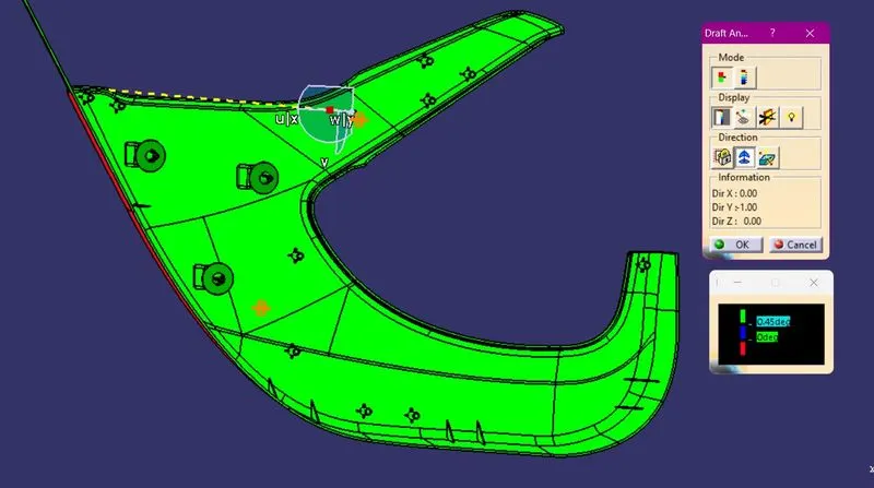
DRAFT ANALYSIS OF CLASS A SURFACE
Draft analysis is done to know wheather the part will be easily manufacturable by the given draft angle or not. It will ensure that the part will not stuck in the core and cavity.
PROCEDURE TO PERFORM DRAFT ANALYSIS:-
- Right Click on Tab < Go to Analysis < Feature Draft analysis
- Put the View Mode in material option
- Align the compass with the tooling direction line
- The surface will turn into green colour it means the part is manufacturable with the given draft angle.
We have given minimum 3deg. draft and the green colour parts are easily removed from the mold.
CREATION OF CLASS B SURFACE
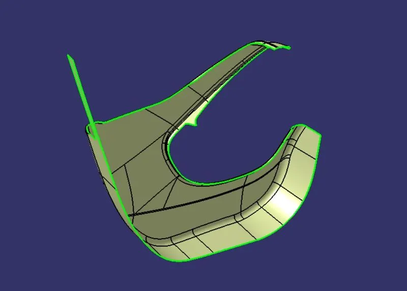
Class B surface is used for Engineering purpose. All the design parameter are done on the Class B surface. We have offsetted the Class A surface for 2.5mm to create CLASS B Surface.
CREATION OF CLASS C SURFACE
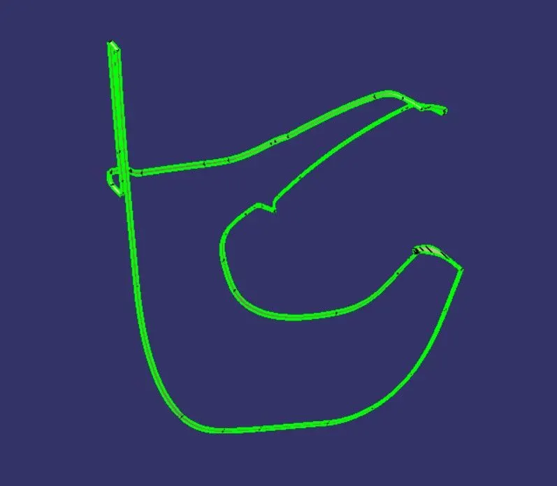
Class C surface is used to join the Class A and Class B surface together. For this surface Customer feels do not need to meet a high cosmetic finish. By using sweep command in CATIA we have created the C surface.
SOLID SURFACE
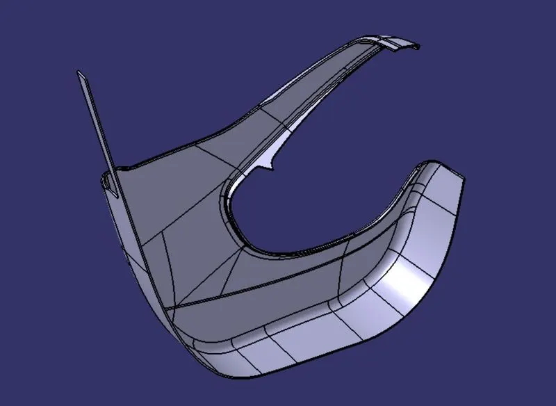
We have first joined the CLASS C surface with CLASS A surface and then trimmed it with CLASS B surface, so it automatically joined together and formed a closed surface then we made it a solid surface.
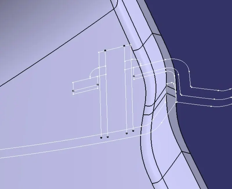
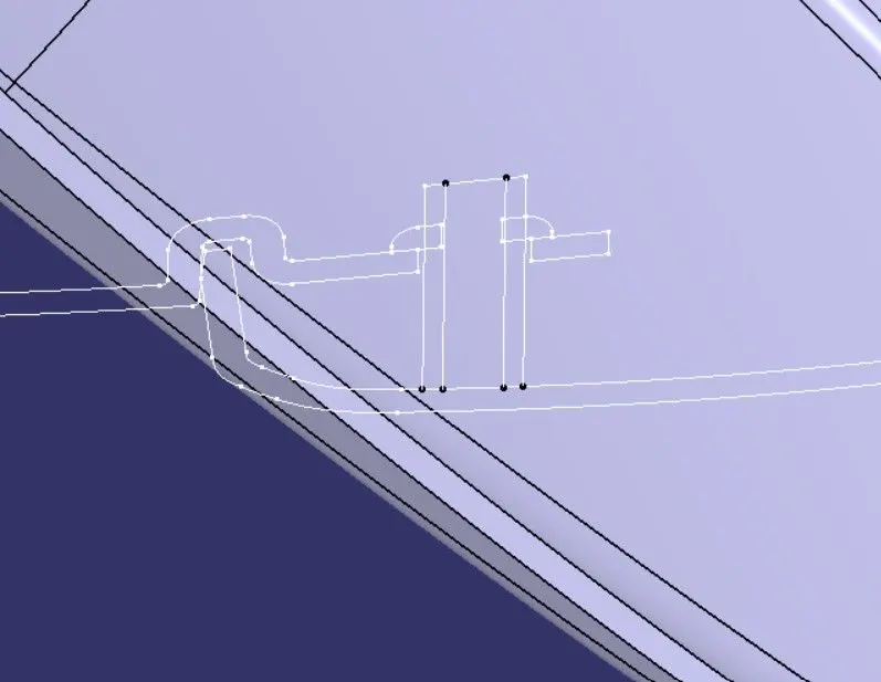
MASTERSECTION OF LOWER SUBSTRAT
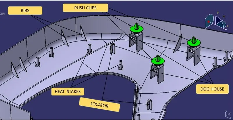
HEAT STAKE CREATION
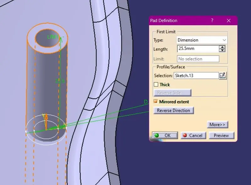
1- We have created a sketch for the heat stake and used PAD command to form it.
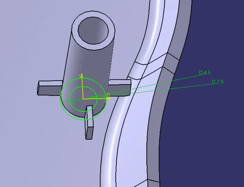
2- We have created sketch of the Heat stake ribs and used PAD command to form it then Used Union Trim Boolean operation.
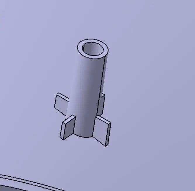
3- Then created points on the surface where it is needed and used TRANSLATE command to Point to Point transfer.
DOG HOUSE CREATION
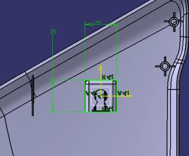
1- We have created a square sketch of 25mm length and breadth and pad it to 45mm
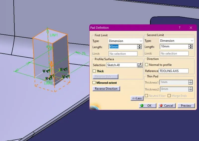
2- For inner side creation we have used SHELL command and given 2.5mm shell thickness then we have given draft to both outer and inner side of 0.5deg.
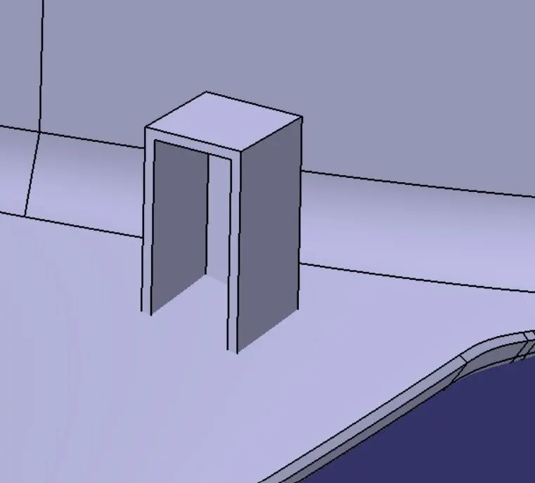
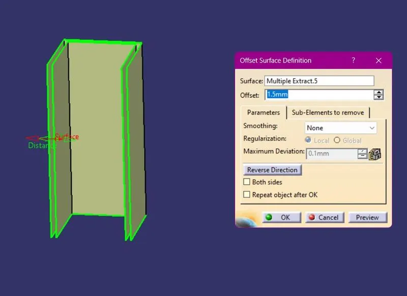
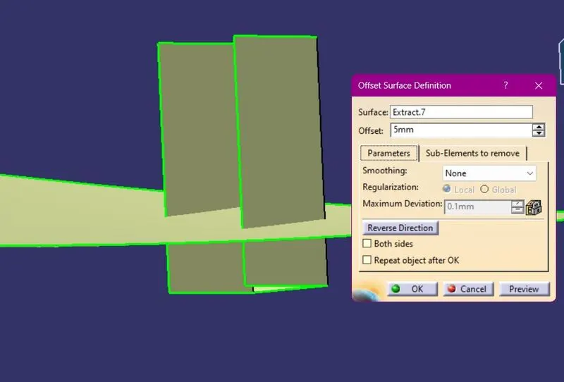
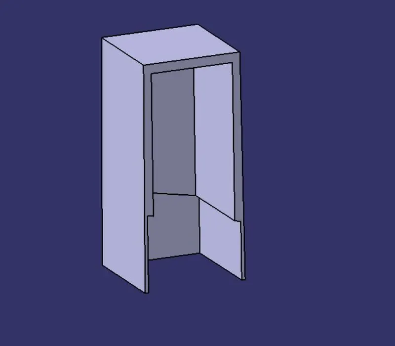
3- For the lower cutout We have used MULTIPLE EXTRACT command to extracted the inner side faces of dog house then we have offsetted it 1.5mm. then we have extract the base surface and extracted it to 5mm then trimmed Both together and used SPLIT command to cut it from the dog house

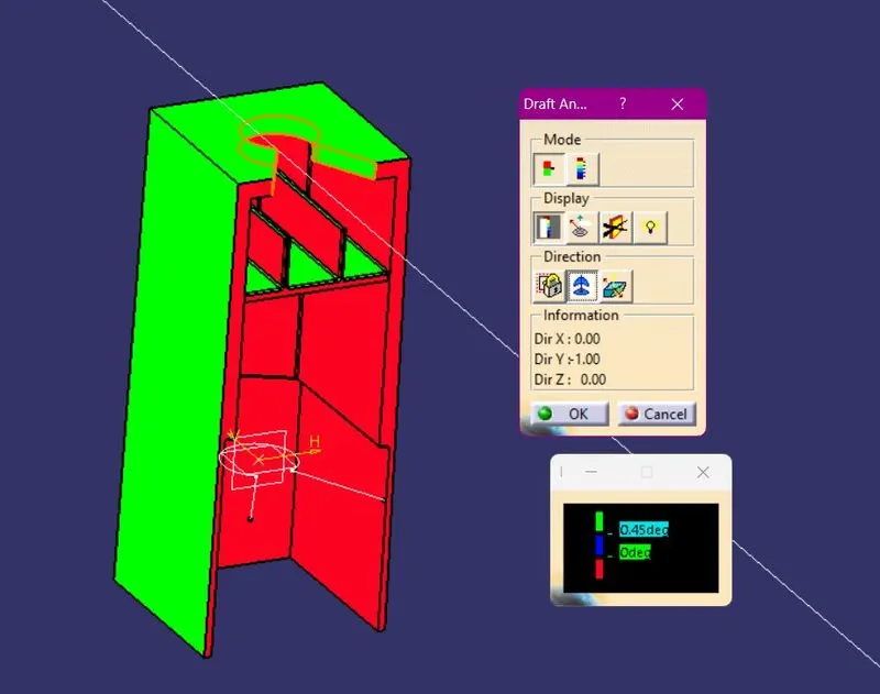
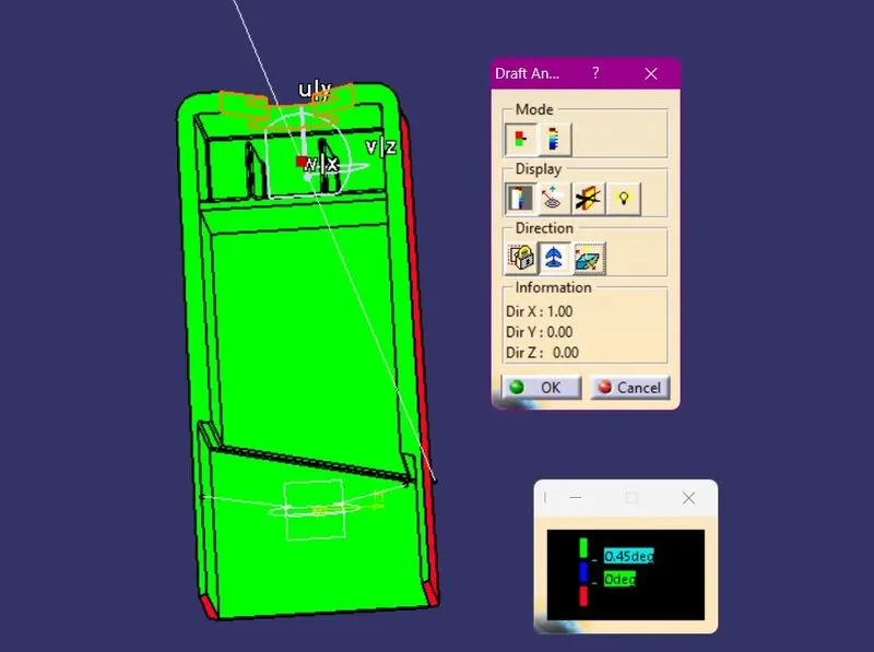
4- We have created a sketch for the ribs and Used PAD command then used Union Trim Boolean operation. then Provided draft of 0.5deg according to the side core axis.
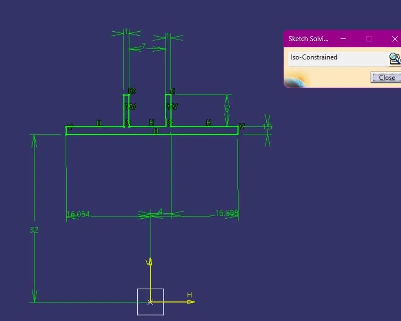
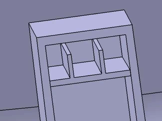
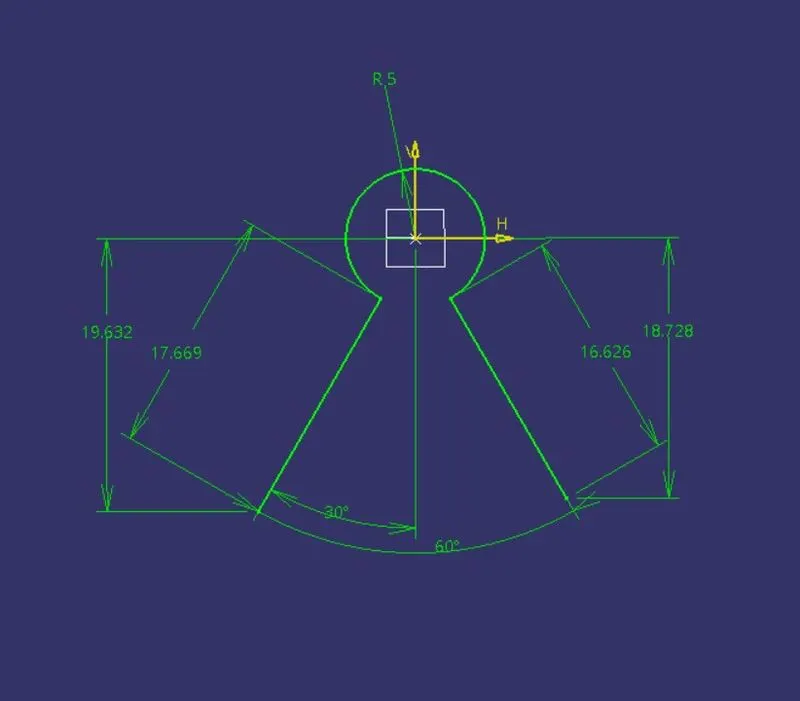
5- We have created a sketch for the upper cutout where Push Clip will be fitted. after sketching we have extruded the sketch and used split command to cut the surface
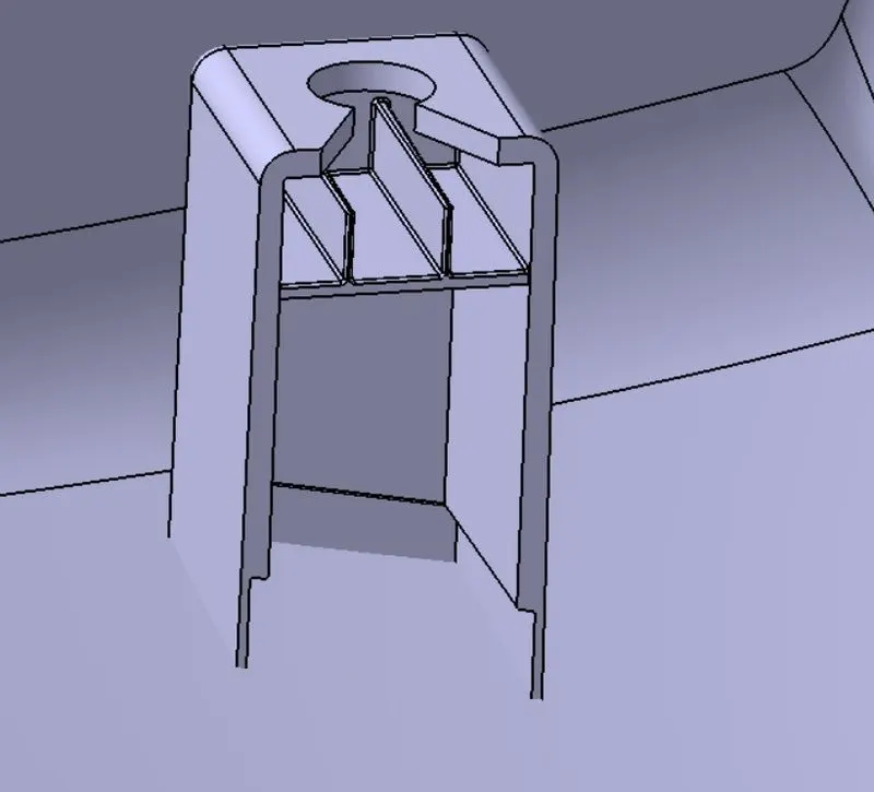
DRAFT ANALYSIS OF DOG HOUSE
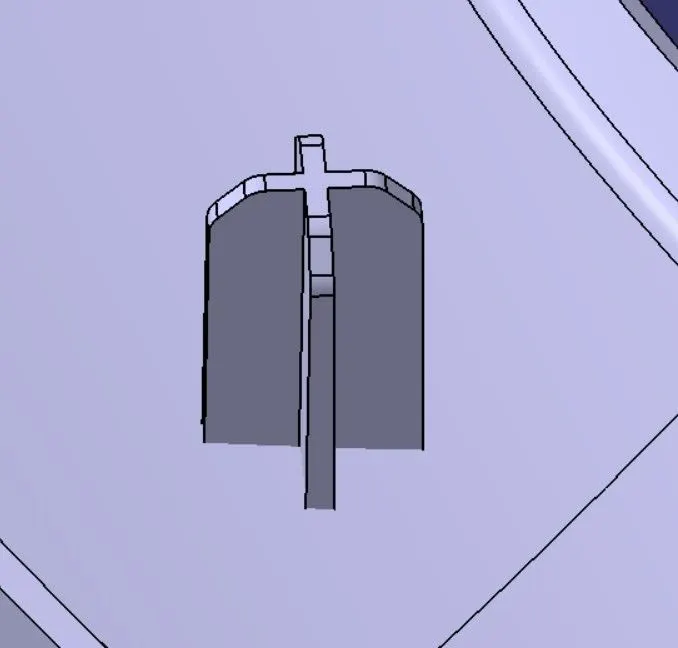
4 WAY LOCATOR
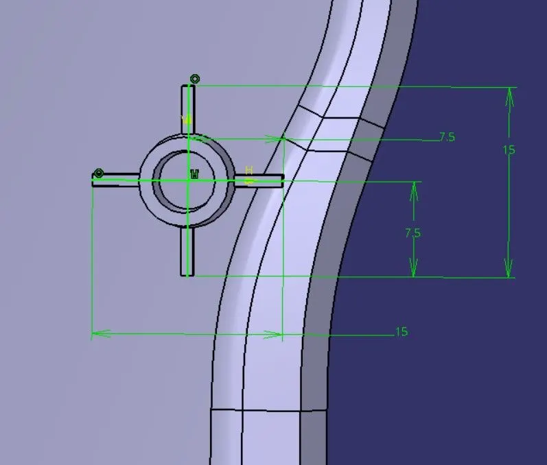
1- First sketch of two lines of 15mm then used PAD command with a thickness of 1mm
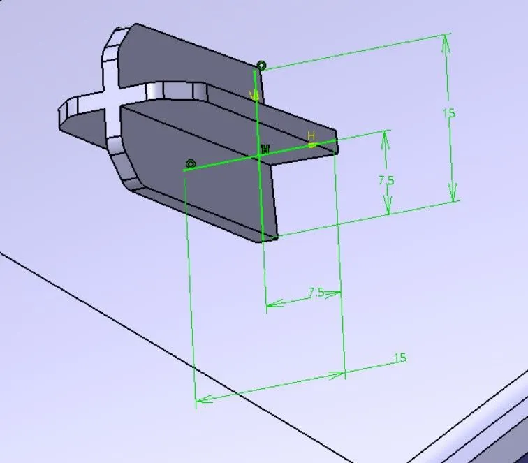
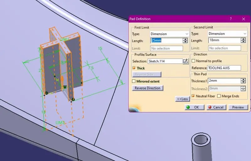
2- Then we have given draft of 0.5deg , chamfer and fillets to the locator. Then create points where ever the locator is needed then translate it Point to point
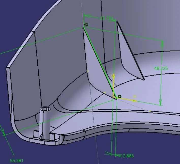
RIBS CREATION
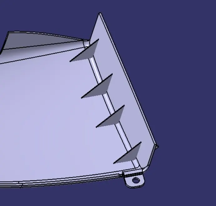
Ribs are provided for the extra support to the part.
ENGINEERING FEATURE
DRAFT ANALYSIS OF FINAL PART
FINAL PART IMAGE
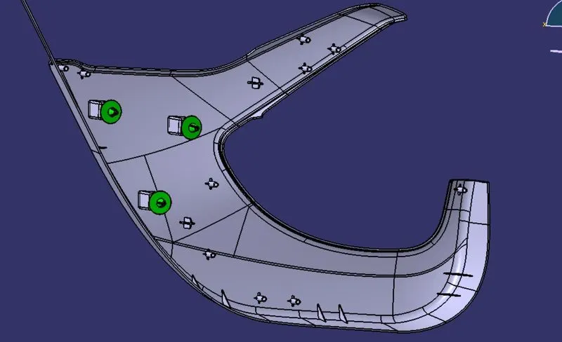
ARM REST DESIGN
PROCEDURE
- Creation of Tooling Axis
- Creation of Class B surface
- Creation of Class C Surface
- Perform draft analysis
- Create Engineering Feature
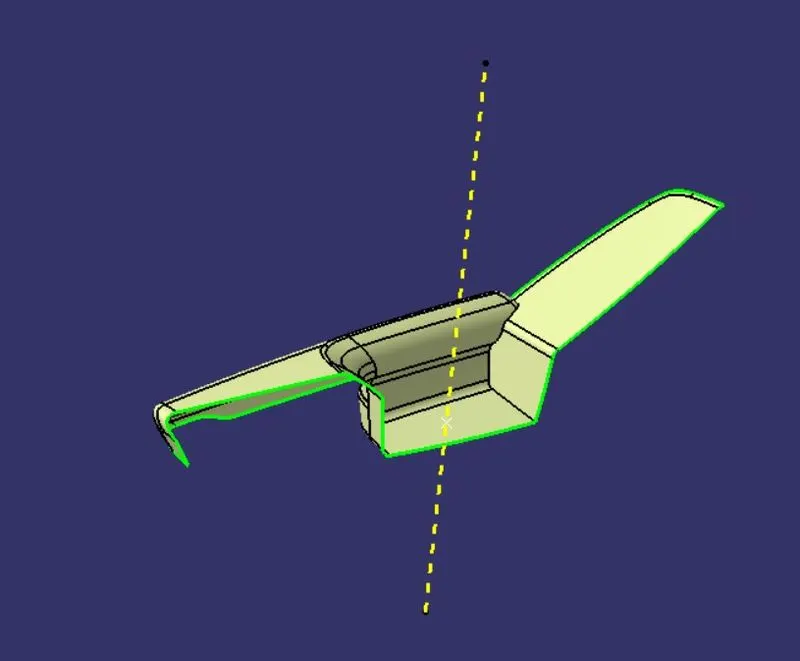
CREATION OF TOOLING AXIS
Tooling axis is the direction in which the mold and cavity opens and closes in the injection molding operation.We have created a point on the surface of the part and created a line, that line is our Tooling axis.
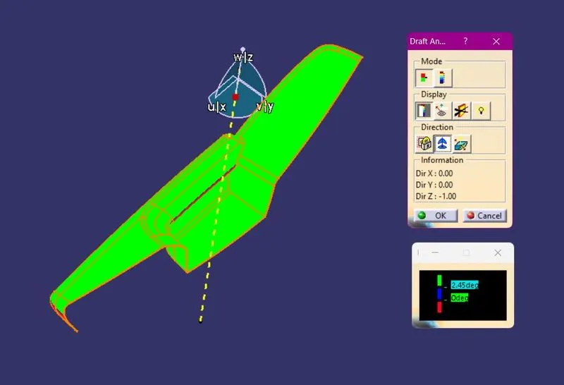
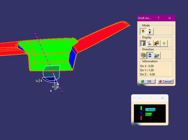
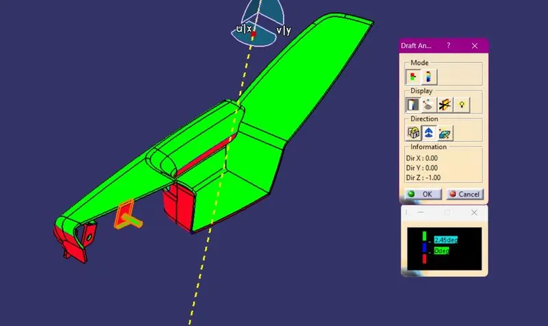
PROCEDURE TO PERFORM DRAFT ANALYSIS:-
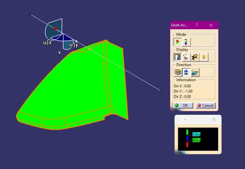
- Right Click on Tab < Go to Analysis < Feature Draft analysis
- Put the View Mode in material option
- Align the compass with the tooling direction line
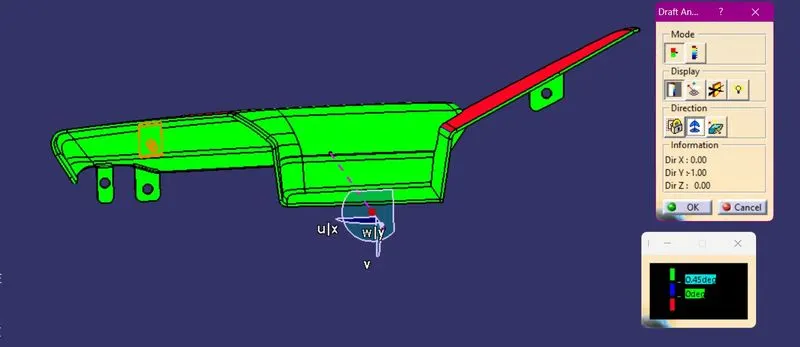
- The surface will turn into green colour it means the part is manufacturable with the given draft angle.
We have given minimum 3deg. draft and the green colour parts are easily removed from the mold.
CREATION OF CLASS B SURFACE
We have offsetted the Class A surface for 2.5mm to create CLASS B Surface.
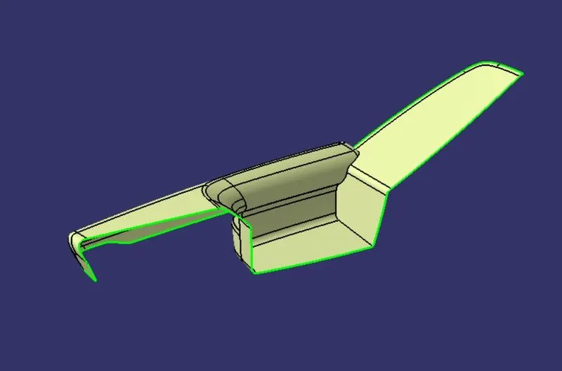
CREATION OF CLASS C SURFACE
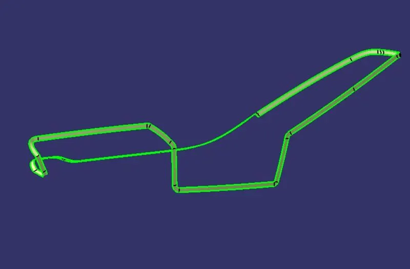
SOLID SURFACE
We have first joined the CLASS C surface with CLASS A surface and then trimmed it with CLASS B surface, so it automatically joined together and formed a closed surface then we made it a solid surface.
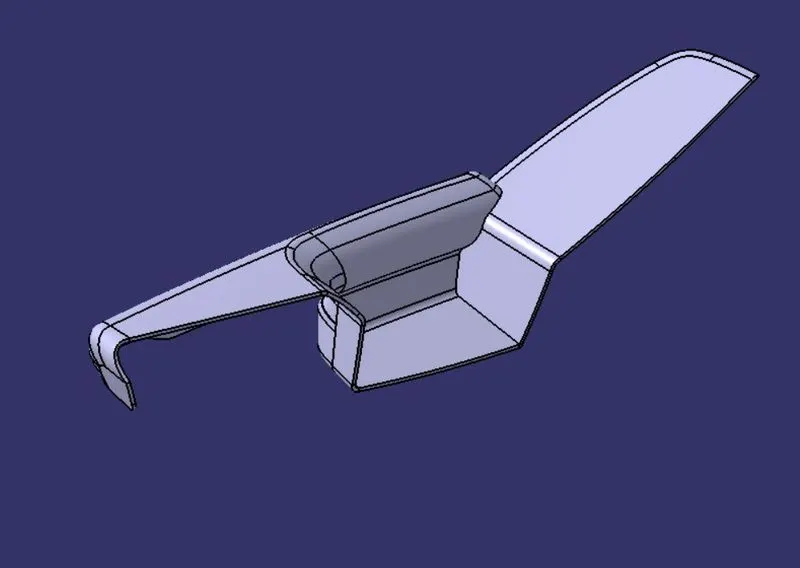
MASTERSECTION OF ARM REST
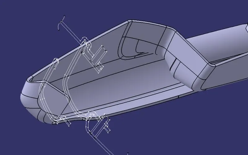
FLANGE CREATION
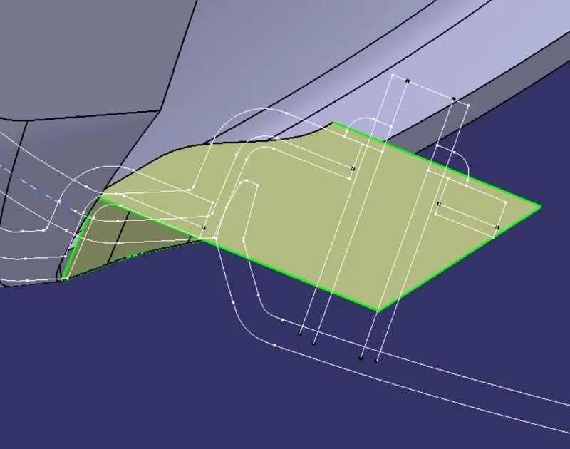
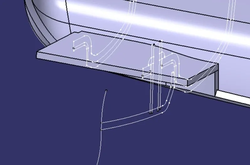
1- We have extracted the lines from mastersection and extruded it to create a normal base surface then converted it into a thick surface of 2.5mm thickness
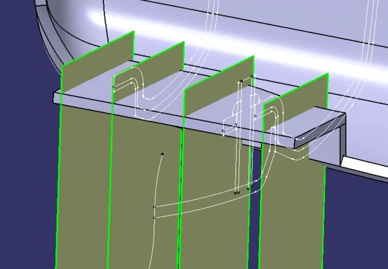
2- Create 4 lines and extrude it for the split operation
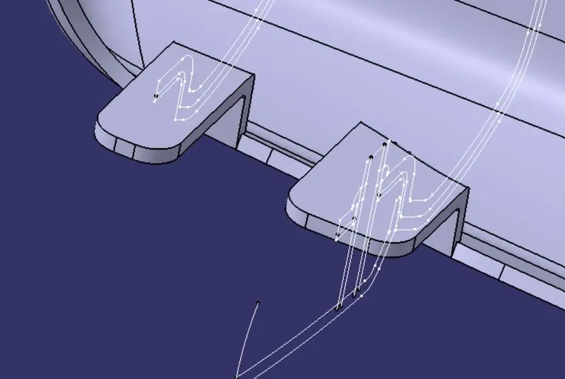
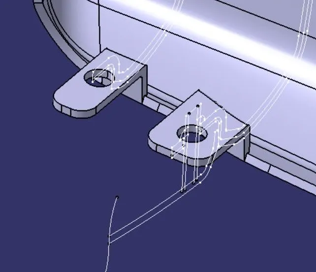
3- We have extracted the surface of the heat stake of lower substrat and offsetted it by 0.5mm and use SPLIT command to create a hole on the flange then we gave draft and fillets to the flange.

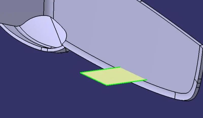
4- For flange 3, we have created a normal surface and converted it into a thick surface of 2.5mm.
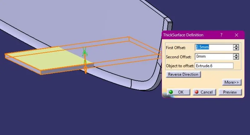
5- We have created a surface for cutout by converting normal surface to thick surface and used Boolean operation to remove from the base surface.
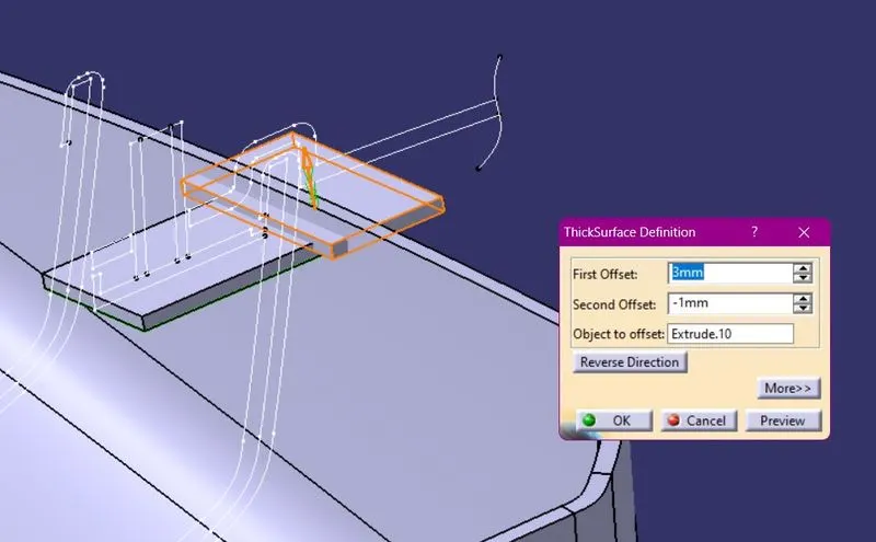
6- We have extracted the surface of the heat stake of lower substrat and offsetted it by 0.5mm and use SPLIT command to create a hole on the flange then we gave draft and fillets to the flange.
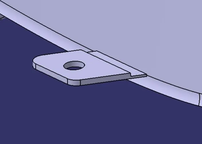
7- By applying these same process, we have created flange 4 according to the mastersection
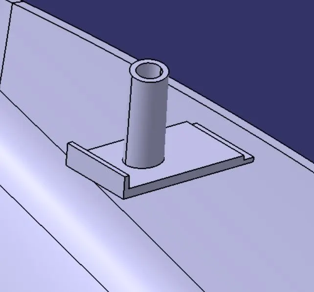
RIBS
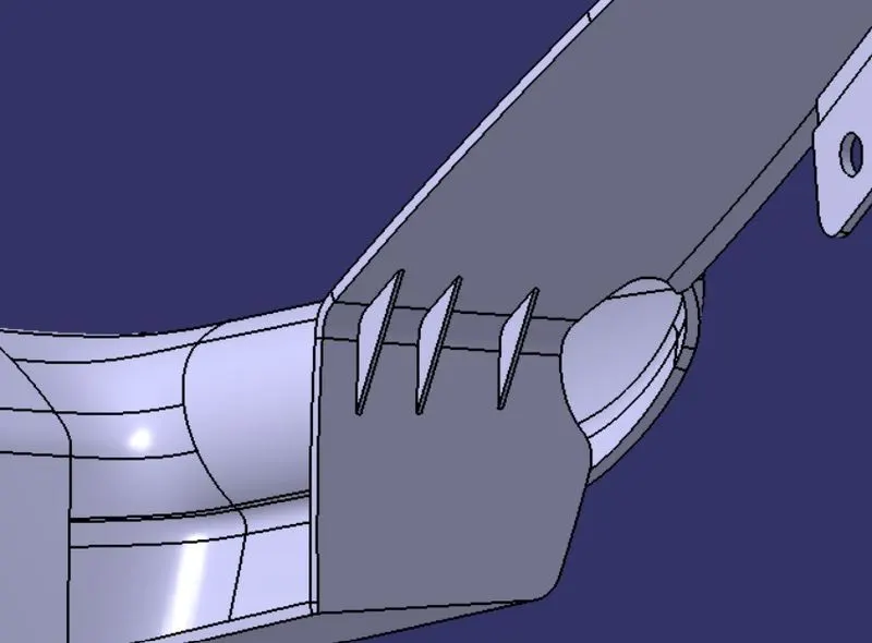
DRAFT ANALYSIS OF FINAL PART
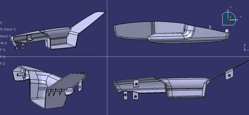
FINAL PART IMAGES
TOP SUBSTRAT DESIGN
PROCEDURE
- Creation of Tooling Axis
- Creation of Class B surface
- Creation of Class C Surface
- Perform draft analysis
- Create Engineering Feature
CREATION OF TOOLING AXIS
Tooling axis is the direction in which the mold and cavity opens and closes in the injection molding operation.We have created a point on the edge of the part and created a line, that line is our Tooling axis.
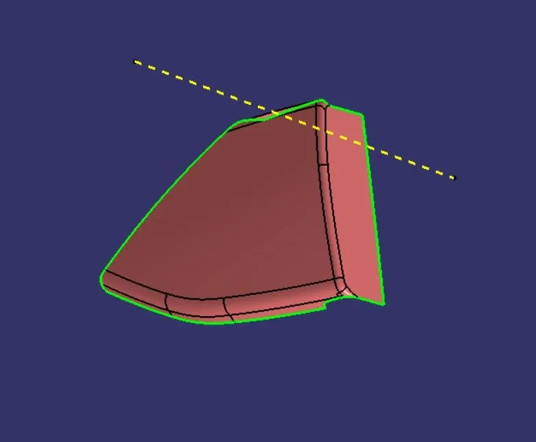
DRAFT ANALYSIS OF CLASS A SURFACE
CREATION OF CLASS B SURFACE
We have offsetted the Class A surface for 2.5mm to create CLASS B Surface.
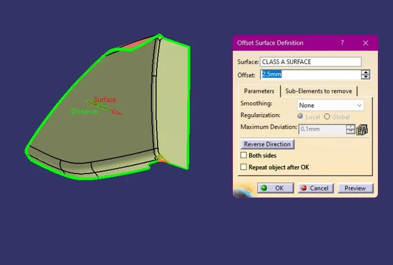
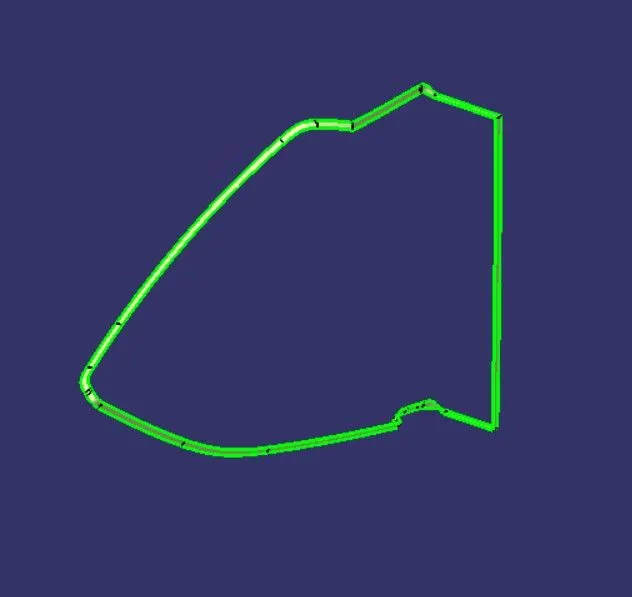
CREATION OF CLASS C SURFACE
Class C surface is used to join the Class A and Class B surface together. For this surface Customer feels do not need to meet a high cosmetic finish. By using sweep command in CATIA we have created the C surface.
SOLID SURFACE
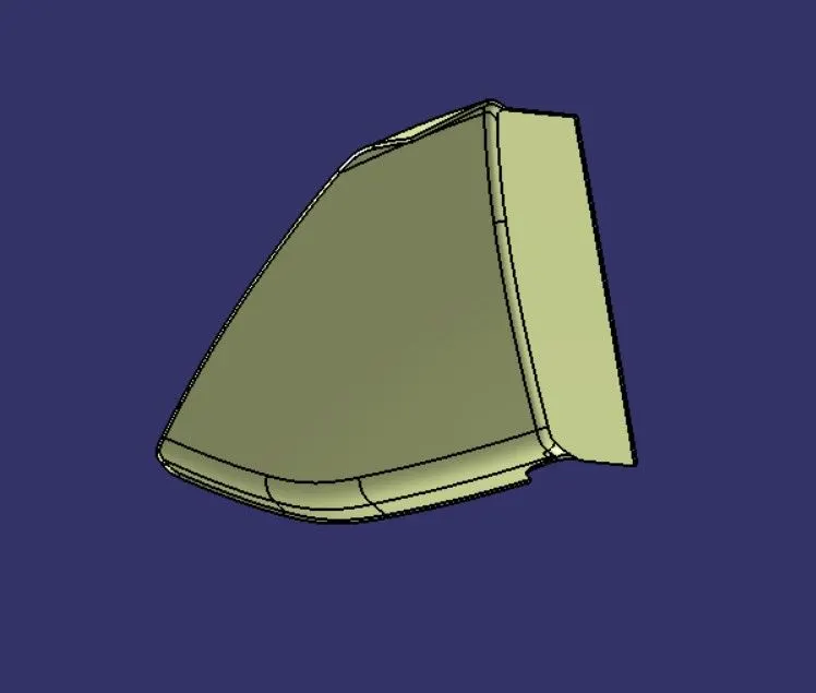
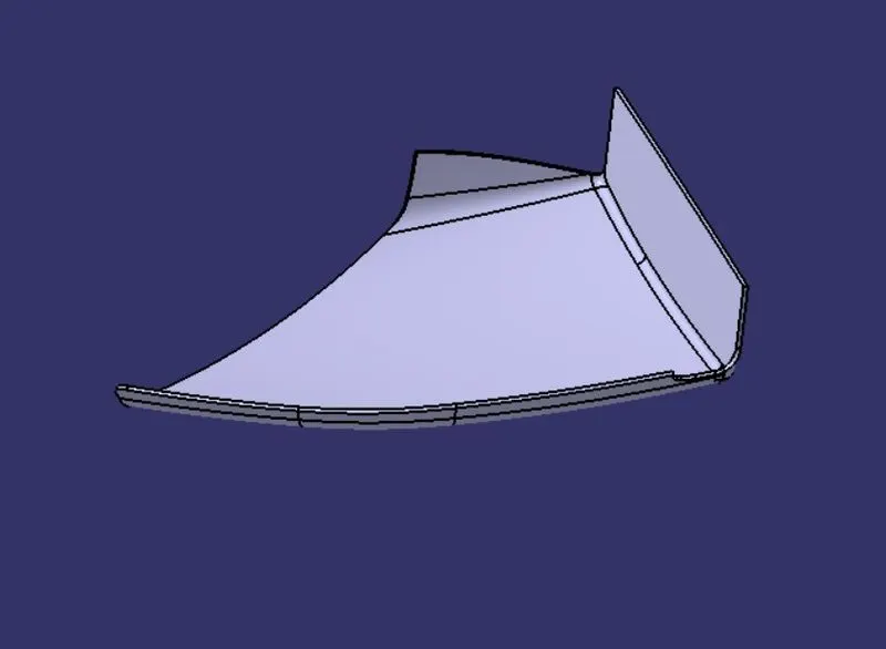
We have first joined the CLASS C surface with CLASS A surface and then trimmed it with CLASS B surface, so it automatically joined together and formed a closed surface then we made it a solid surface.
MASTERSECTION OF TOP SUBSTRAT
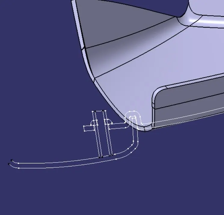
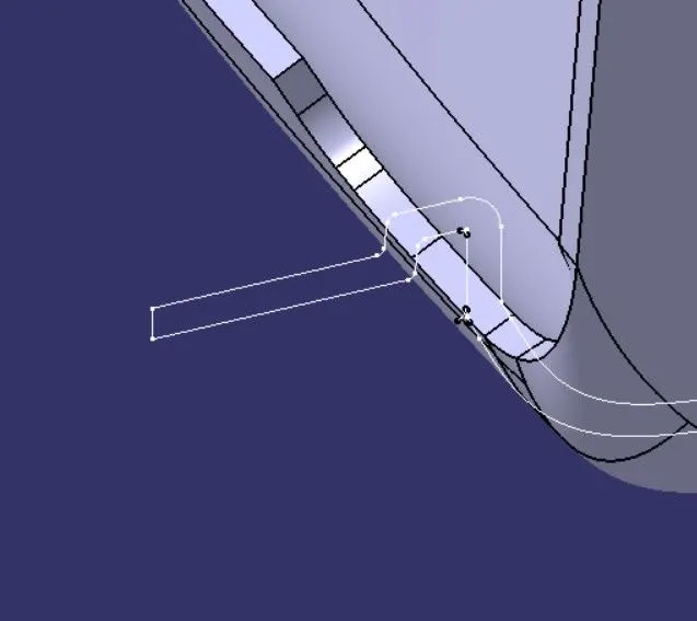
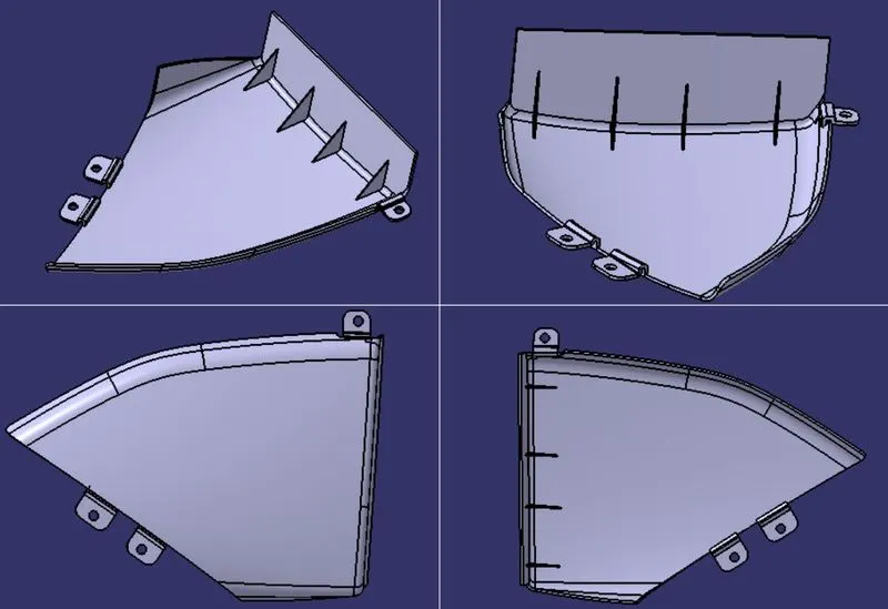
FLANGE CREATION
1- First create a normal surface then convert it into a thick surface
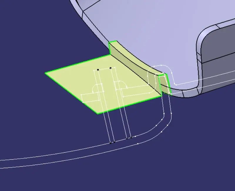
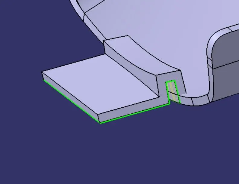
3- Split that surface into 2 parts using a surface
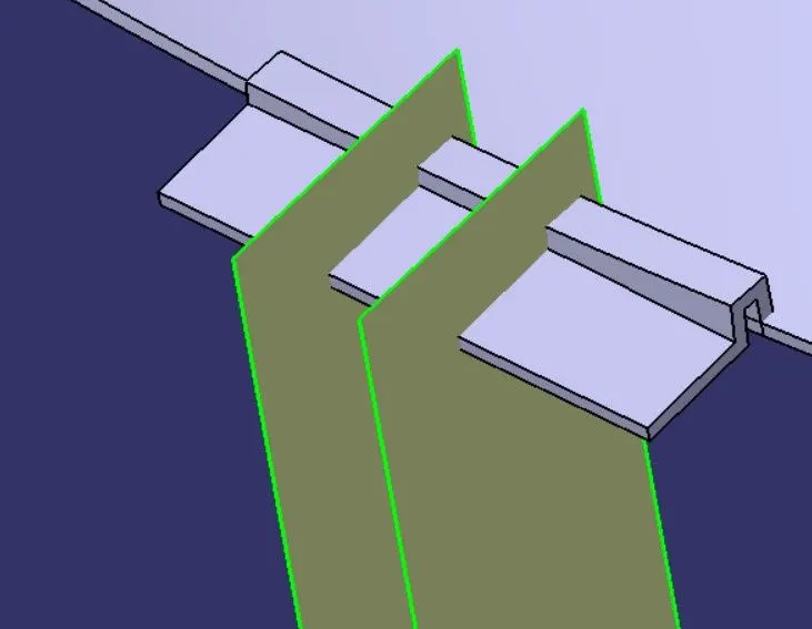
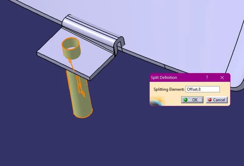
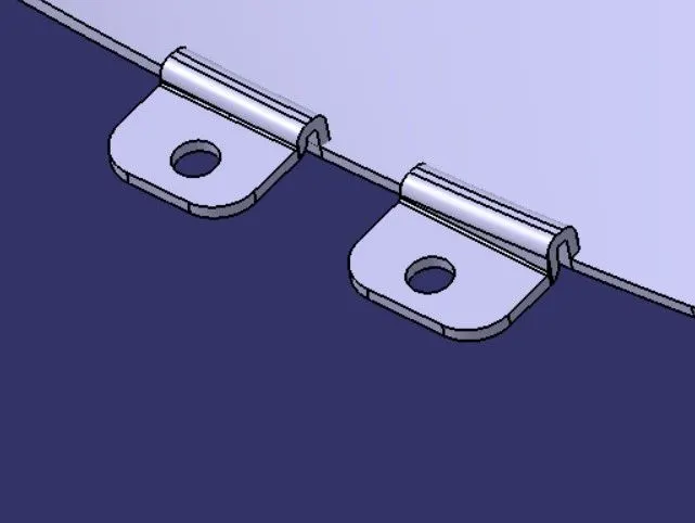
4- Use lower substrat heat stake extrat to create holes on the flange
RIBS CREATION
DRAFT ANALYSIS OF FINAL PART
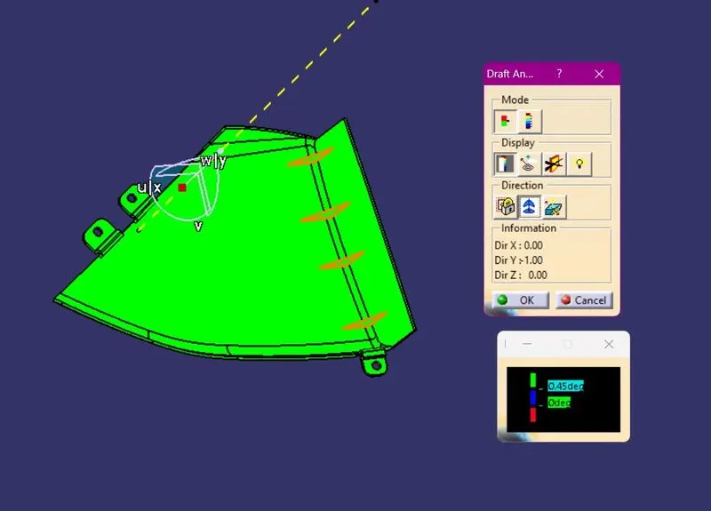
FINAL PART IMAGES
MAP POCKET DESIGN
PROCEDURE
- Creation of Tooling Axis
- Creation of Class B surface
- Creation of Class C Surface
- Perform draft analysis
- Create Engineering Feature
CREATION OF TOOLING AXIS
Tooling axis is the direction in which the mold and cavity opens and closes in the injection molding operation.We have created a point on the edge of the part and created a line, that line is our Tooling axis.
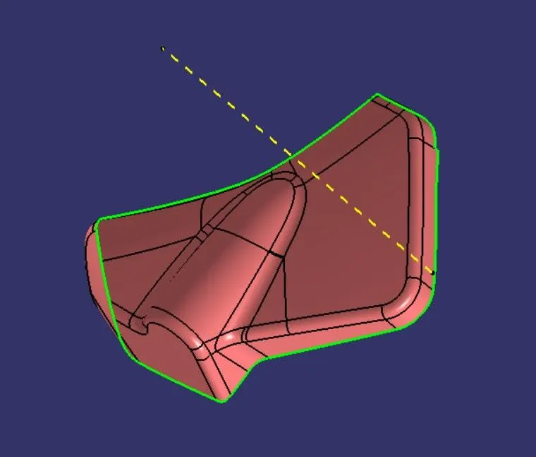
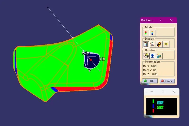
DRAFT ANALYSIS OF CLASS A SURFACE
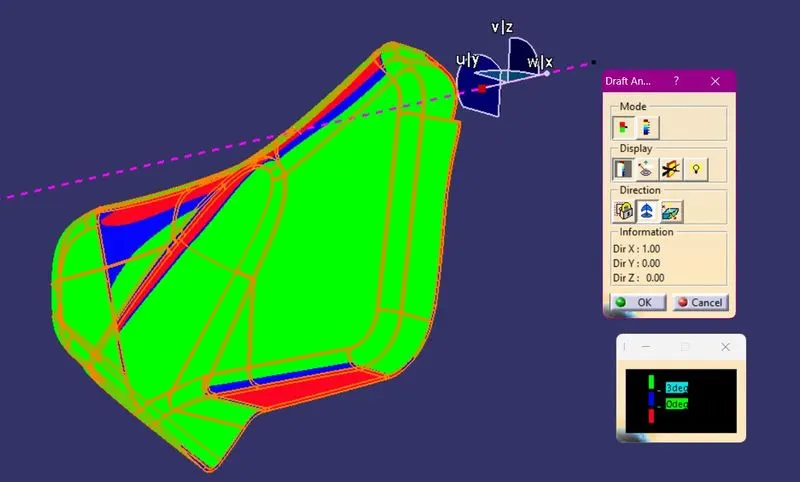
Draft analysis is done to know wheather the part will be easily manufacturable by the given draft angle or not. It will ensure that the part will not stuck in the core and cavity.
PROCEDURE TO PERFORM DRAFT ANALYSIS:-
- Right Click on Tab < Go to Analysis < Feature Draft analysis
- Put the View Mode in material option
- Align the compass with the tooling direction line
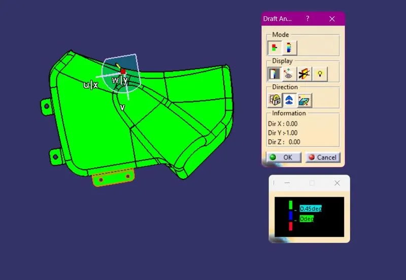
- The surface will turn into green colour it means the part is manufacturable with the given draft angle.
We have given minimum 3deg. draft and the green colour parts are easily removed from the mold.
CREATION OF CLASS B SURFACE
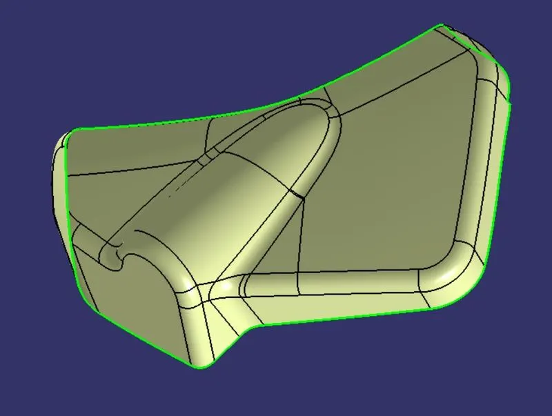
We have offsetted the Class A surface for 2.5mm to create CLASS B Surface.
CREATION OF CLASS C SURFACE
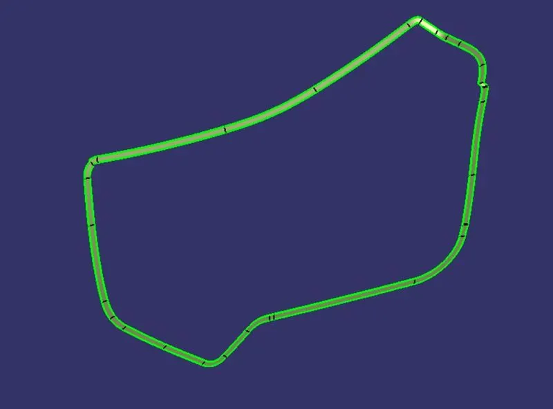
Class C surface is used to join the Class A and Class B surface together. For this surface Customer feels do not need to meet a high cosmetic finish. By using sweep command in CATIA we have created the C surface.
SOLID SURFACE
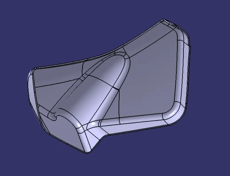
We have first joined the CLASS C surface with CLASS A surface and then trimmed it with CLASS B surface, so it automatically joined together and formed a closed surface then we made it a solid surface.
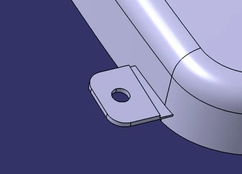
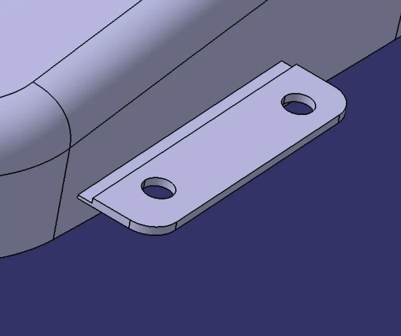
FLANGE CREATION
1- First we have created a normal Surface by extruding a line, then we convert it into a thick surface of 2.5mm thickness
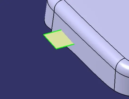
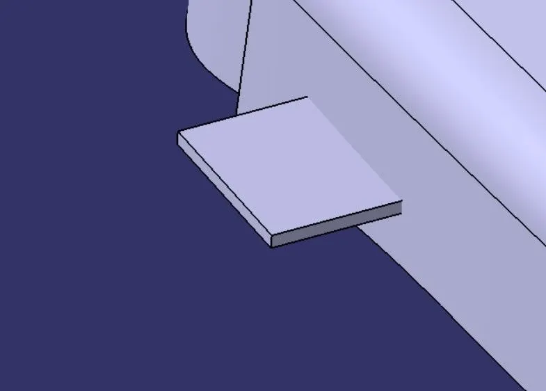
2- We have created a surface for cutout by converting normal surface to thick surface and used Boolean operation to remove from the base surface.
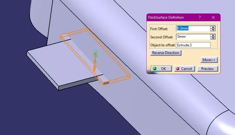
3- We have extracted the surface of the heat stake of lower substrat and offsetted it by 0.5mm and use SPLIT command to create a hole on the flange then we gave draft and fillets to the flange
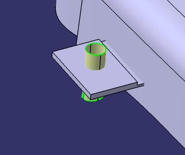
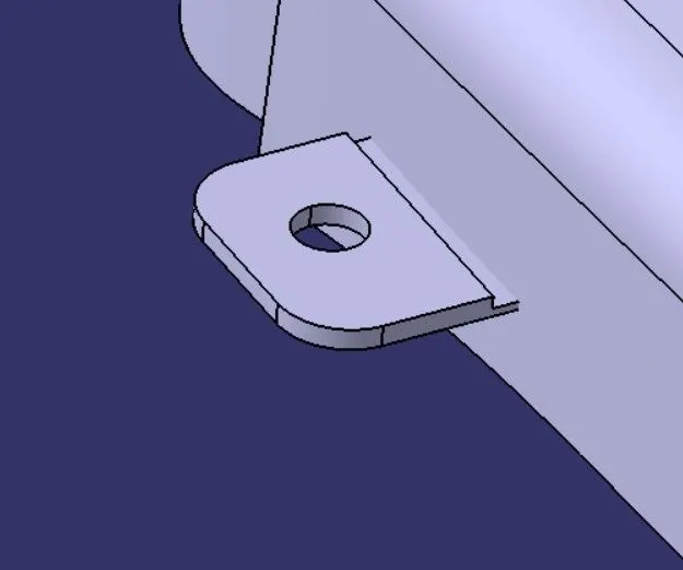
4- By this process we have created 2 more flanges
DRAFT ANALYSIS OF FINAL PART
FINAL PART IMAGES
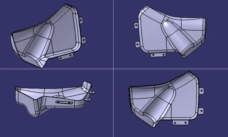
FINAL DOOR TRIM PANEL IMAGE