Fender Design
OBJECTIVE:- Design a front fender using the given master section and fender skin data.
FENDER:- Fender is the part of an automobile vehicle body that frames a wheel well.The fender car part is the body kit or body part installed on the left and right sides of the vehicle. Manufacturers usually attach fenders to the wheel arches.Its primary purpose is to prevent sand,mud,rocks and other road sprays from being thrown into the air by the rotating tire.If there was nothing covering the wheels, all kinds of road particle would be kicked up by the rotating tires and it could damage the car and the pedestrians also.It also enhance the aerodynamics and aesthetic of the car.
Most passenger vehicles have four fender one over each wheel.For vehicles with a narrow car body that exposes the tire,fender is an exposed curve over the top of the tire.For wide body vehicle that cover the tire,the fender forms the wheel well surrounding the tire and is not directly visible from above the car body. (Fender are also a styling part so we don't give it to the suppliers,we develope it in our production house.)
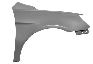
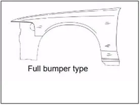
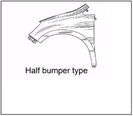
TYPES OF FENDER:- 1)FULL BUMPER TYPE, 2)HALF BUMPER TYPE
FULL BUMPER TYPE:- It was used in old car.it covers the wheel till the bumper, it looks like half circle.In full bumper type the blank we use to create this is really big and their is a lot of wastage around and because of this it increases the weight of the car.
HALF BUMPER TYPE:- Recently half bumper type is in use in every automobile company. It cover half of the wheel and other half part is cover by the bumper. Because of its small size we can create two fender at the same time by slightly increasing the blank size.This will reduce the blank cost so that we can provide good fender at a cheap price to the customers. This method is allow us to use a lot of plastic on the bumper,it will reduce the weight and increases the performance of the vehicles.
There are 5 mounting point for front fender:-
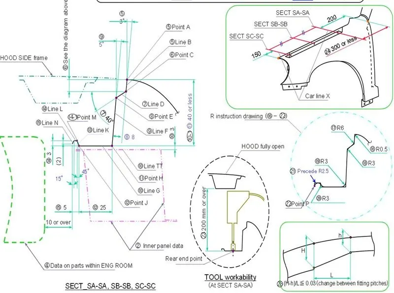
1)Drip Area- In this region fender gets fastened in the engine compartment. This area has given a clearance of 200mm from back where the cowl gets attached and 150mm from front for the headlamp placement.We need to maintain minimum 10mm gap between engine compartment and drip mounting region.
2) A pillar- This mounting region is located near the cowl where the wipers are gets attached. Fender gets fastened in this region under the windshield.
3) Bumper- Bumper is the plastic front part of the car.Fender gets fastened in this region.
4) Baffle- On this region baffle is attached with clips with the fender which protect the car from mud and chips.
5) Sill- This mounting region is located below of the fender near the door edge.
PROCEDURE:-
1) We have received the fender skin data,after receiveing we check where we are going to create the mounting regions.
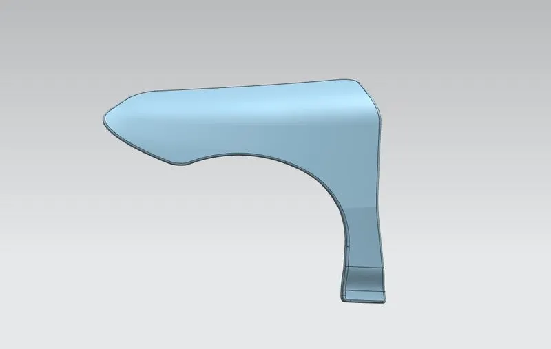
2) We proceed by using curve on surface command, we create smooth curves to cut the part for the different mounting region.
3) At first we created drip mounting area by following the given master section. While creating this region We should maintain 200mm from back and 150 mm from front, then we extend the sheet by using law extension and create this region with proper dimension mentioned in the master section.Darts are given to increase the strength of the part.
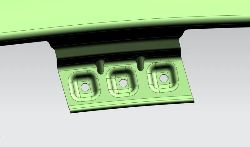
3) After drip area, we created A pillar mounting region by cutting and extending the sheet by using law extension then created mounting point for fastner. Then we created emboss and gave dart to provide strength to the part.
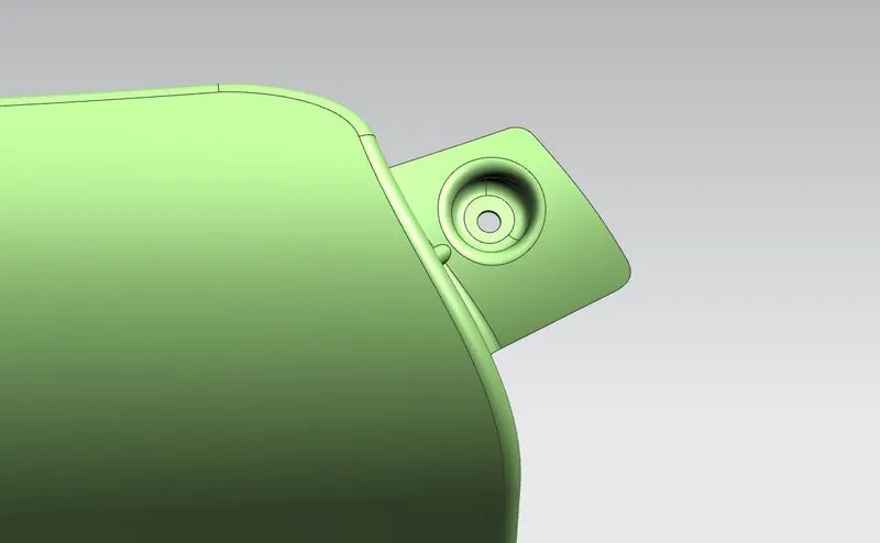
4) We created bumper mounting point by using law extension command and gave 2 mounting point for fastener and created dart and embosses for strength.
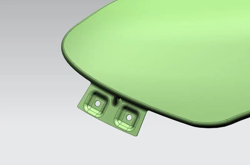
5) Then we created baffle mounting points,in this we simply give smooth curves for cutting, we dont need to extend the sheet for this region we only created holes to attach the baffel.
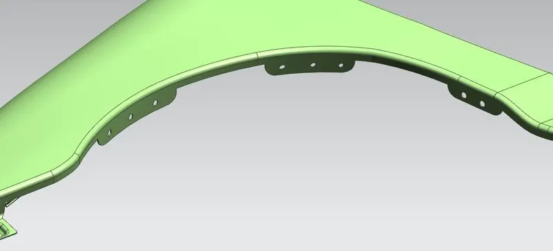
6) After baffle region we created sill mounting point to fastened the fender below.
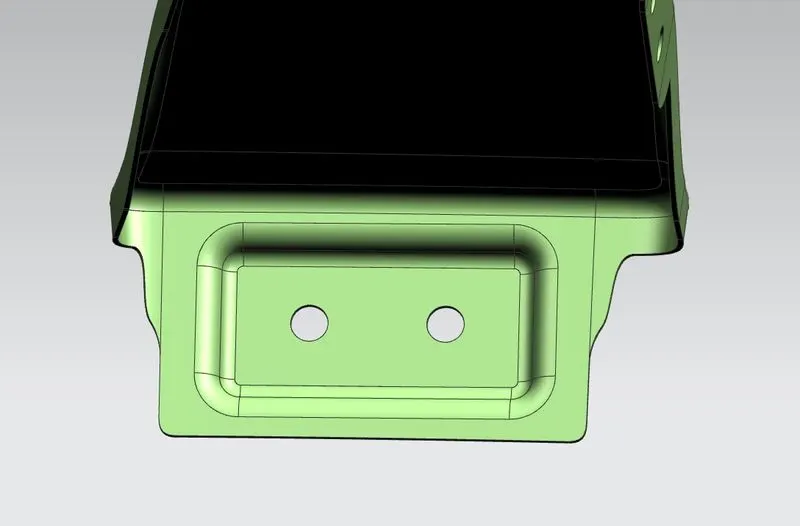
We avoided all sharp edges while creating the regions to prevent the stress concentration and gave smooth curvature in every mounting region. At the end of process we gave 0.75mm thickness to the fender.
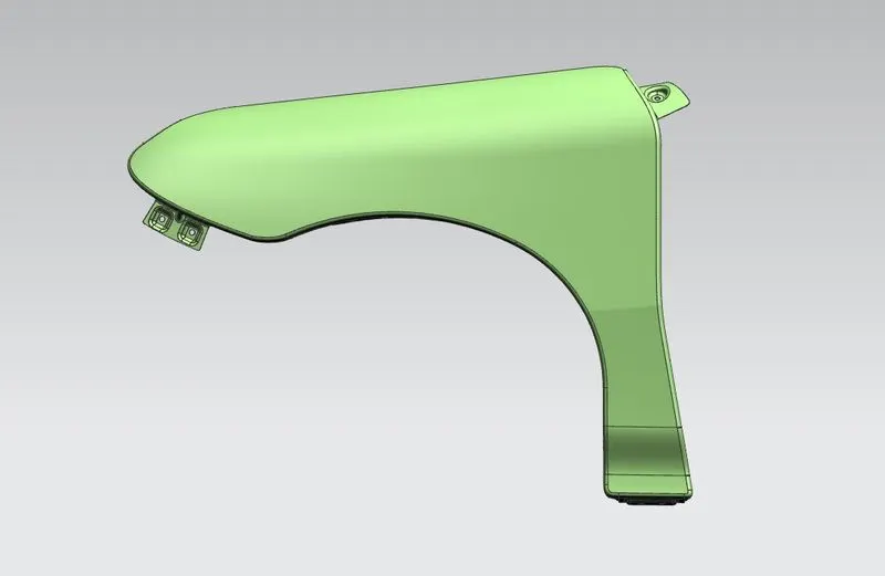
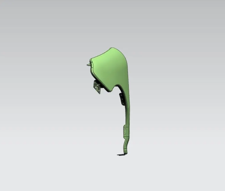
FINAL FENDER MODEL
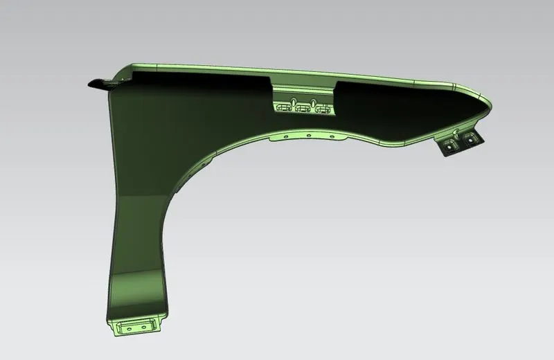
CONCLUSION
This fender is designed in NX CAD by following the given master section and design parameter.