Week 11 - Final project
Aim :-
- The Objective Of this project report is that the explanation of steps and procedure followed while developing the Door Trim Panel of a car using CATIA V5. Using the CLASS-A surface and master sections as input, to create a Tooling axis, CLASS-B surface, CLASS-C surface, Flanges and form a solid body after which the attachment features such as Dog House, Push Pins, Heat stakes, etc are created.
Theory :-
Why we used plastic in Automotive Industry ?
-
The use of polymers as plastics in the construction of automobiles has continued to grow over the last decades. Nowadays they are the second most commonly found Material in cars.
Here are four reasons why plastic is used in car manufacturing:
- Plastics reduce the weight of cars
- Plastics and polymers contribute to the safety of cars
- Plastics help to lower car manufacturing costs
- Polymers advance the design of vehicles
- Polymers have revolutionised the performance, safety, construction and functionality of cars. Parts made of plastics are resistant to corrosion, offer flexibility and resilience for added safety, have very good thermal insulation, reduce noise and allow optimum space utilization.
- Plastics have been used widely in vehicle claddings to improve fuel efficiency by making vehicles lighter and reducing corrosion due to salt and water on metal surfaces. Although plastics have been used for decades both externally and internally, many automotive manufacturers have now switched to making bioplastics and polymers, instead of relying on fossil-based plastics, to improve their carbon footprint and promote sustainability.
- There are about 30,000 parts in a vehicle, out of which 1/3 are made of plastic. In total, about 39 different types of basic plastics and polymers are used to make an automobile.
- More than 70% of the plastic used in automobiles comes from four polymers: polypropylene, polyurethane, polyamides and PVC. Plastic has become one of the key materials required for the structure, performance, and safety of automobiles in recent years, with growth in plastic consumption being driven by light-weighting trends for fuel efficiency and consequently lower greenhouse gas emissions.
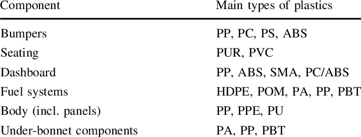
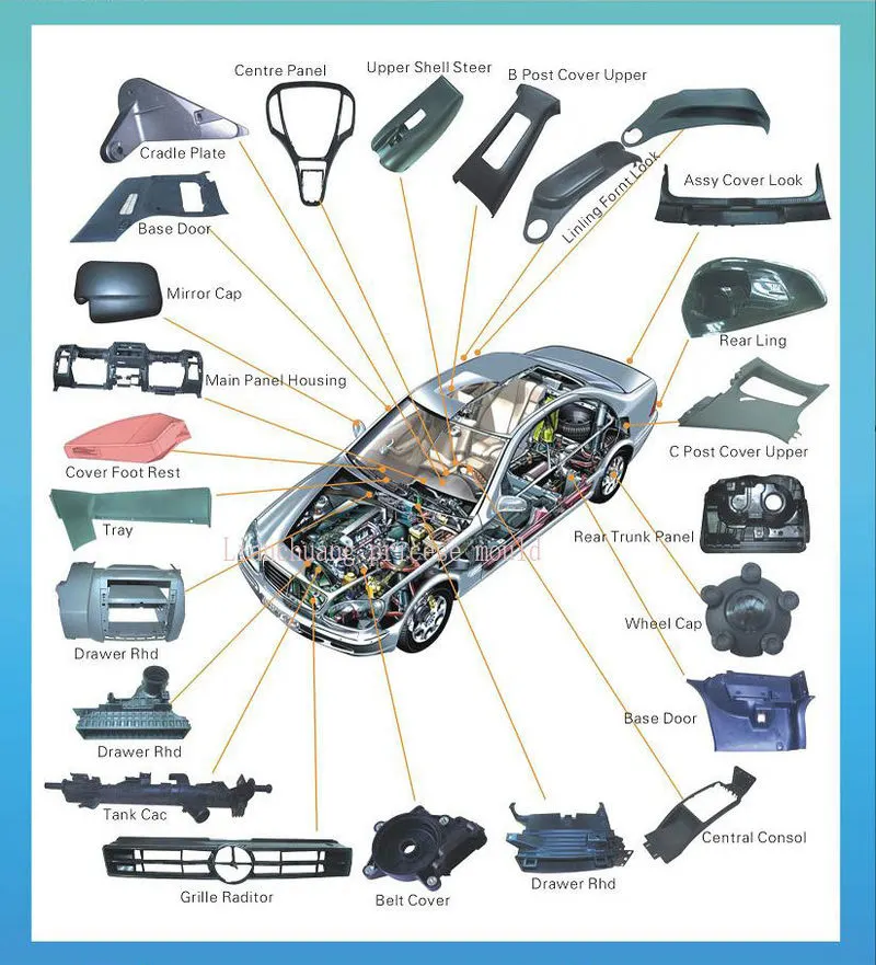
There are some different catagory of plastic used in Various component of the car :-
Manufacturing Process Used in Making Of plastic Component :-
Injection Moulding :-
-
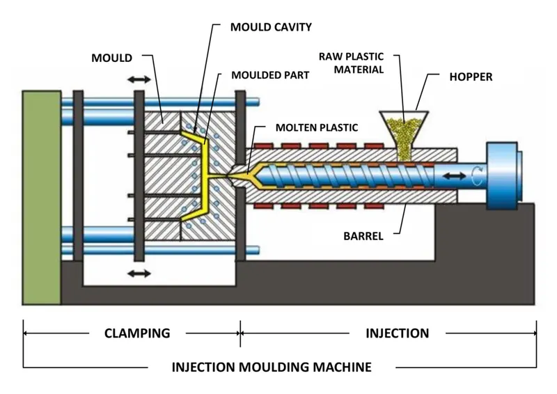
Injection moulding is one of the most commonly used production processes for plastics. It offers a viable solution for the mass production of high-quality injection automotive parts from a broad range of polymers.
-
In the automotive industry, where consistency, safety, and qualities are most importance, automotive plastic injection moulding is an important manufacturing process.
-
Plastic injection moulding is the process of melting plastic pellets that once malleable enough, are injected at pressure into a mould cavity, which fills and solidifies to produce the final product.
Tooling Direction :-
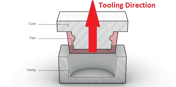
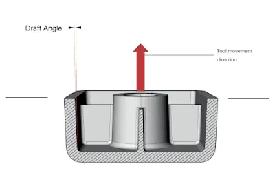
- In Molding machine arrangement is given to open the mold along a direction which is known as Tooling Direction.
- In other words. The mold is built from two separate halves (Core and Cavity) and tooling direction basically define the direction of mold pulls apart.
- Tooling direction is known as primary direction.
- Core is the male part of the mould which holds the inner design of the component and the cavity is the female part which holds the outer shape of the component.
Design for Manufacturing & Assembly (DFMA) :-
- Design for Manufacturing and Assembly is an engineering methodology that focuses on reducing time-to-market and total production costs by prioritizing both the ease of manufacture for the product’s parts and the simplified assembly of those parts into the final product – all during the early design phases of the product lifecycle.
- Before becoming the singular philosophy it's known as today, DFMA used to be considered as two distinct methodologies: Design for Manufacturing (DFM) and Design for Assembly (DFA).
- DFM is concerned with selecting cost-effective raw materials and attempting to minimize the complexity of manufacturing operations during the product design phase in order to reduce the overall manufacturing time and costs for product components.
- Similarly, DFA is concerned with reducing the product's assembly time, costs, and complexities by minimizing the number of individual parts, assembly steps, and the potential for variability in build quality.
Role Of Engineering Feature(Heat stakes,Dog House,Locator,Rib) :-
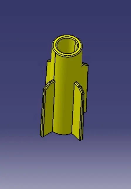
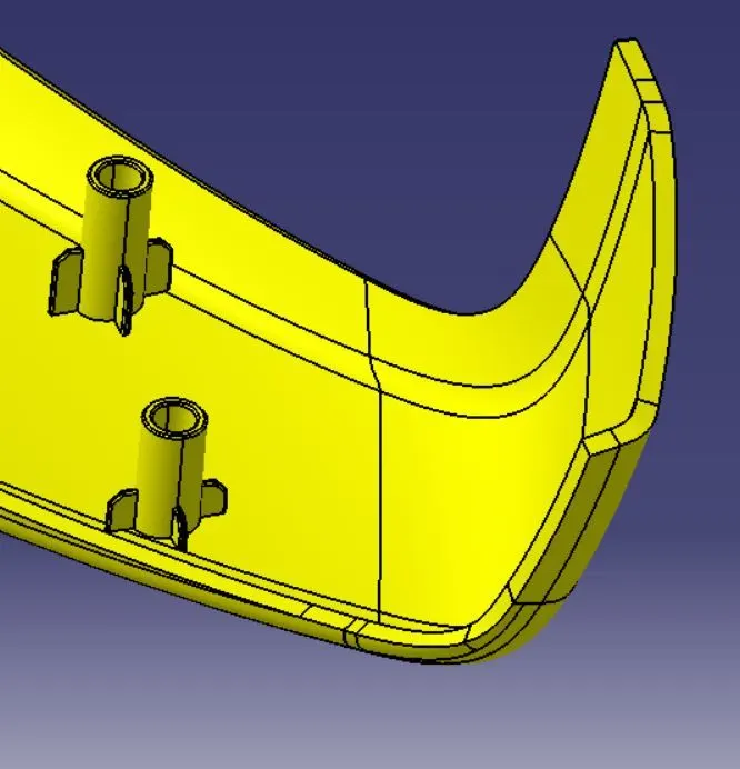
- Heat staking technology is quite simple in concept. Whenever two or more components need to be attached to one another, and at least one is made of a thermoplastic, a combination of heat and pressure can be used to reform the plastic to the many shapes or profiles to retain or join the parts together.
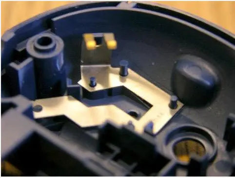
- A 2-way locating pin restricts motion along 1 axis (or 2 degrees of Freedom). Likewise, a 4-way pin restricts 4 degrees of freedom along 2 axes.
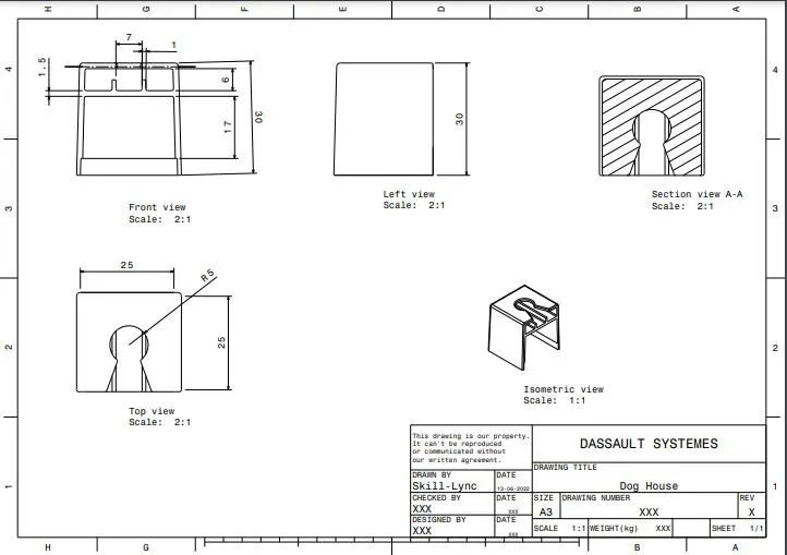
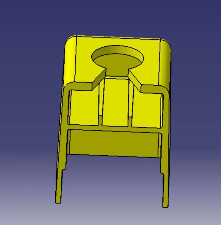
- Dog house is a 4 sided box attached to a flat surface which usually requires a riser/slider to mould. In other words, it has 3 sides and a roof, where the roof usually has a hole for attachment purposes.”
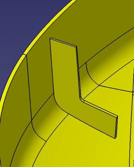
- Ribs can be added to parts to add rigidity or stiffness. Adding ribs allows for a part to increase strength and bear a higher load.
Automotive Plastic Trim:-
- The design of Automotive Interior and Exterior plastic components is called Trims. The plastic components that you see inside the car are Interior. Ex: Dashboard, Instrument Panel, Doors, seating, and pillars. Plastic components that you see outside of a car are Exterior. ex: bumper, light assembly, hoods.
Door Panel in Car :-
- Door panels serve as an interface between the interior of the car and the inner workings of the door, and between vehicle occupants and the door.
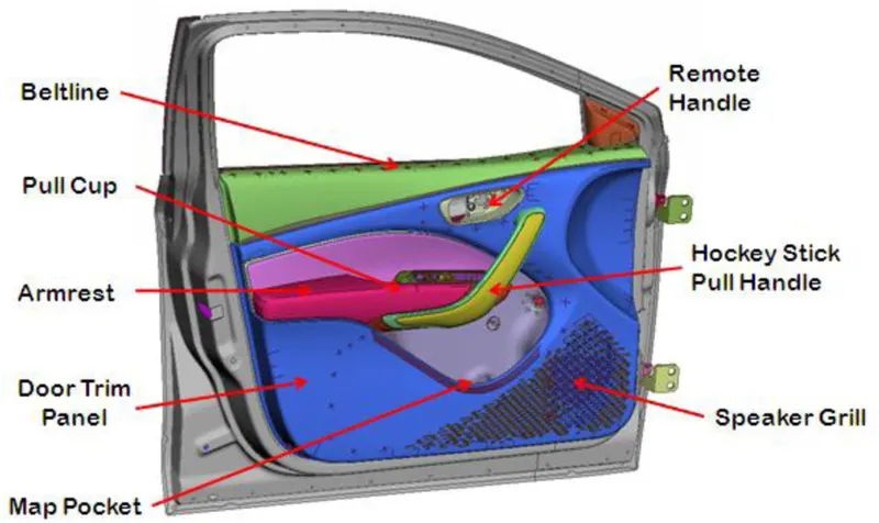
- They are expected to meet a variety of design specifications regarding safety, aesthetics, and functionality. In addition, they are expected to continue the material theme of the dashboard and pillars while concealing intricate electrical and mechanical components for operating locks, windows, and other features.
- The door panel has evolved from a simple two-part system of latch and simple winding mechanism to a more sophisticated enclosure.
- Doors currently have an inner full-width panel consisting of electronic windows, central locking system, and speakers. These panels typically consist of a foamed core covered with either textiles or plastics
OBJECTIVES:-
- Extracting the Class-A Surfaces and the Master Section.
- Analysing the class A and performing necessary modification to obtain the modified class A.
- Creating the tooling axis for all the components .
- Performing draft analysis of class A surface.
- Creating the class B surface with the help of surface workbench.
- Creating the class C surface with necessary draft.
- Trimmimg the CLASS A,B AND C Surface for obtaining the final trim for all the components.
- Creating the closed body for all the components.
- Creating the attachments on the LOWER SUBSTRATE for assembly like DOG HOUSE, HEAT STAKES, AND RIBS.
- Creating the flanges on the other three components for the assembly purpose.
- Creating the Side core tolling axis.
- Performing the vigrous draft analysis and make sure all parts are clearing with positive and required draft.
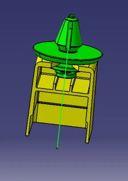
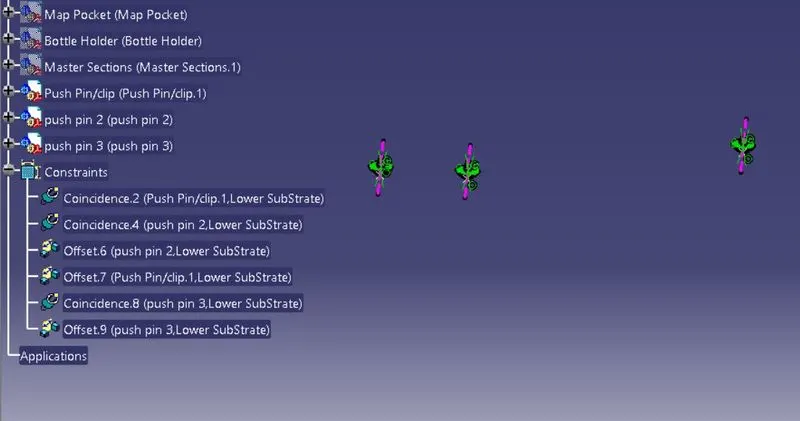
- Assembly of the push pins over the dog house in assembly workbench.
- Final submission.
The first step to follow in this project is to extract the CLASS-A surface (individually for each component) of the Door Trim Panel and divide these surfaces into different Geometrical sets as follows.
- Lower Substrate
- Map Pocket
- Bottle Holder
- Arm Rest
We first check the given styling surface for any error in the surface elements. To do this we have to first extract the styling surface and then join it with the merging distance of 0.001 mm. This will show where the surface elements are weak. These weak sections have to be improved. The joined surface is then given as an input to the A-surface geometrical set.
We have to ensure that the Class A Surface for each part is connected as one single profile,to do that take Input file which has a single Geometric set with all the surfaces of the Class A Door trim then We have to extract and assign the respective surfaces to each component.
Class-A Surface :-
- Class-A (or 'Strak') is a term used in specifically in automotive design. It describes the final production surface data for the aesthetic parts of the car.
- The term 'Class A' is often misunderstood, but it's generally seen as the 'Holy Grail' of Surface Modelling. This is because as it achieves the highest surface quality levels, and it demands a high level of automotive design knowledge as well as surface modelling skills.
- Class A represents the 'craftwork' end of the design process. Creating the main surface shapes to describe the vehicle is the primary design activity. But the painstaking, detailed craftsmanship of perfecting those surfaces, designing flanges and panel gaps is what guarantees that a beautiful design turns into a beautiful manufactured product.
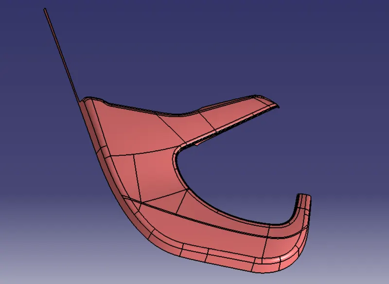
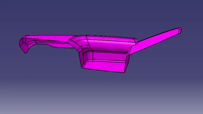
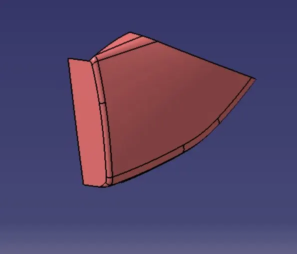
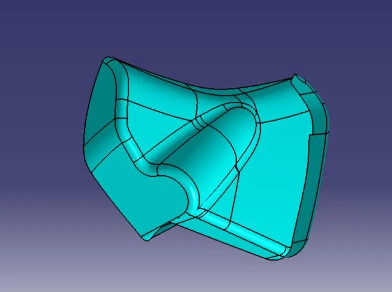
- Here we have four class A surfaces as inputs:
Lower Substrate :-
Arm Rest :-
Map Pocket :-
Bottle Holder :-
Tooling Axis Creation :-
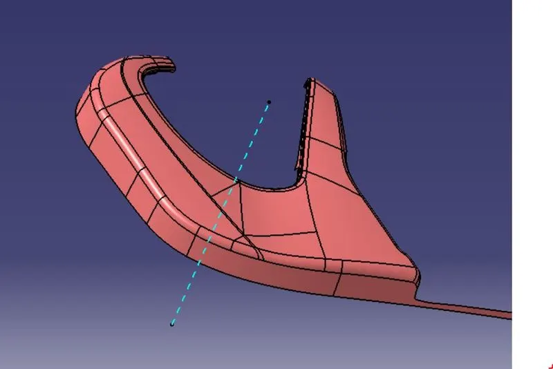
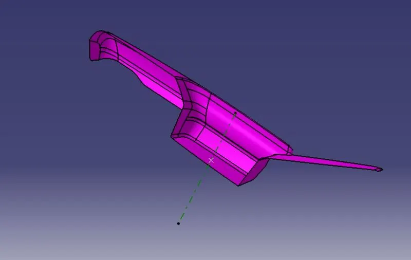
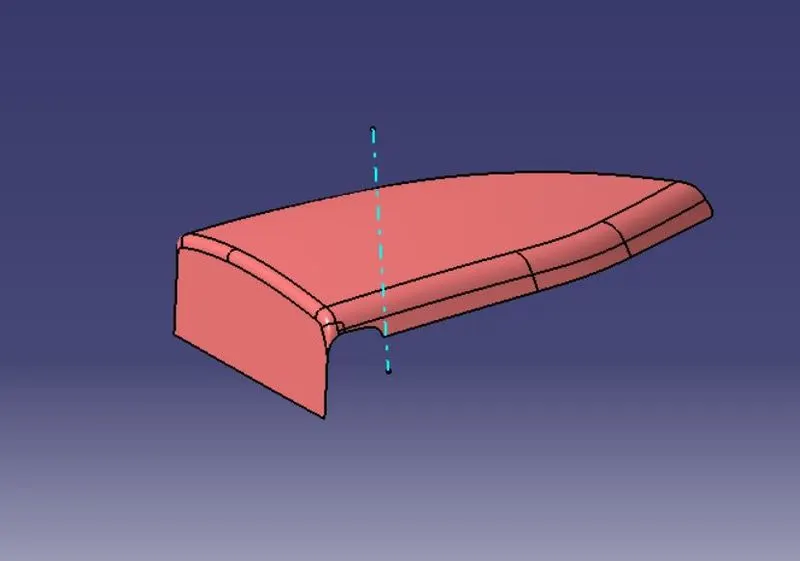
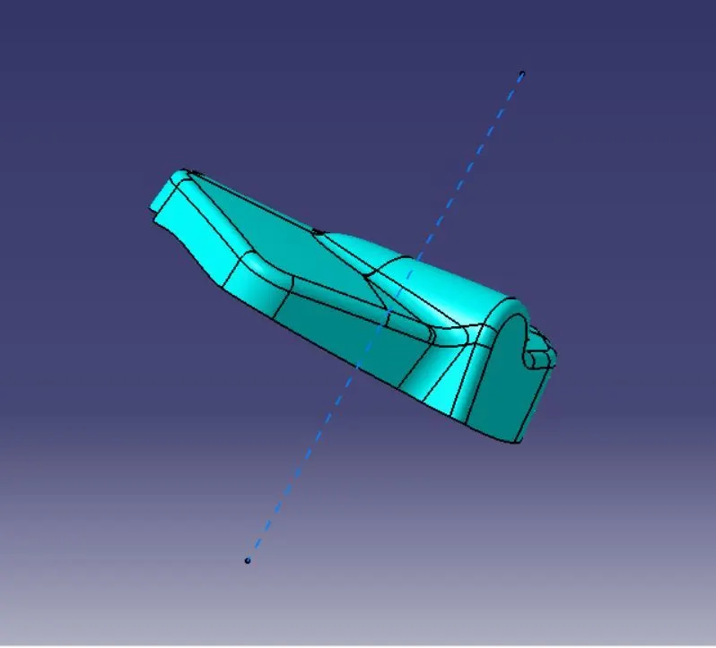
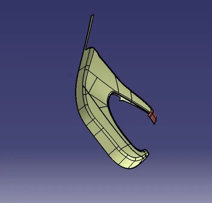
- Tooling axis plays important role in plastic product manufacturing and designing, this axis decides the direction in which mould is going to work while production of the component.
- The main focus while deciding the tooling axis is clearing the component in the moulding in the same axis with the minimum use of the side core for producing the component, the side core usually adds up to the cost of the component.
- For the particular component X,Y and Z can be the possible direction for the tooling axis.
- You must specify the axis system by creating the point on the surface.
- With the help of the intersect in the YZ plane create the tooling axis in YZ plane .
- With the help of the intersect in the ZX plane create the tooling axis in ZX plane.
- We Can Create Tooling Axis Normal to the Surface, Choose a Flat Surface create a Point On the Surface , make a Line which is Normal to the Surface.
Lower Substrate Tooling Axis :-
Arm Rest Tooling Axis :-
Map Pocket Tooling Axis :-
Bottle Holder Tooling Axis :-
Class-B Surface creation :-
- Class B surfaces are the secondary surfaces that you may see sometimes or may not, but are less important. These must be smooth and "error-free" as well, but are not held to the standards that class A surfaces.
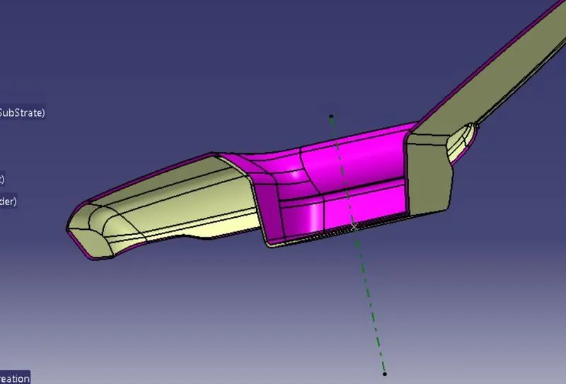
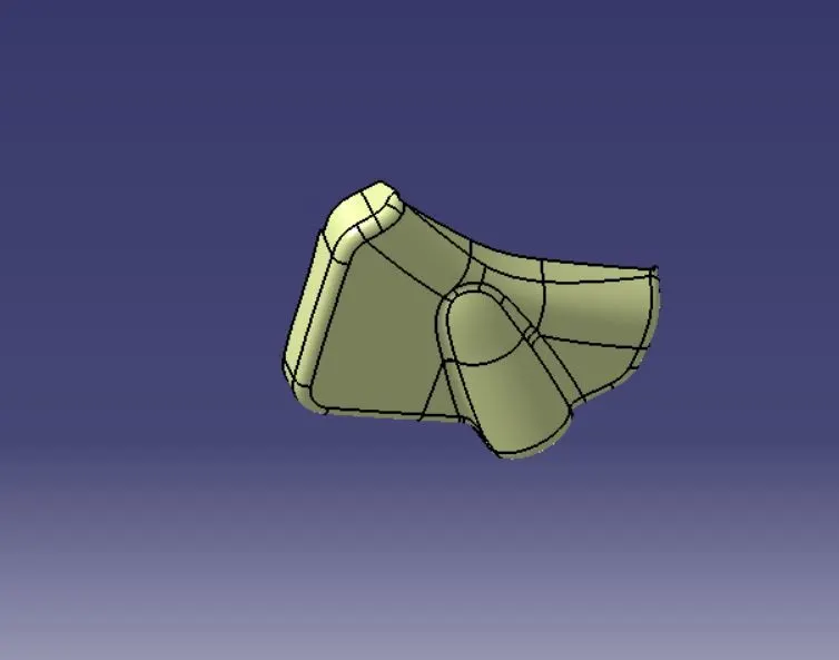
- After creating the Tooling axis, B surface is to be created which is nothing but the surface parellel to the A surface.
- B surface contain all the fillets and the edges which the A surface containsDepending on the geometry, the extraction and offset of the fillets might generate non-uniform thickness.
- So it is advisable to extract only the flat surfaces and then apply fillets at the end of Class B formation.
- The extrapolated parts are then made offset with reference to the class A with the thickness of the component, here thickness of the component for base bracket is 2.5 mm.
- The offset surfaces are then trimmed to attain the class B surface.
- You can even directly offset the class A for obtaining the class B surface.
- The final class B surface must have the edge fillets similar to the class A and fillets must be given properly with a thought of maintaining same thickness throughout avoiding the flow line defects.
These are the Class-B surface of all Individual Part :-
Lower Substrate :-
Arm Rest :-
Map Pocket :-
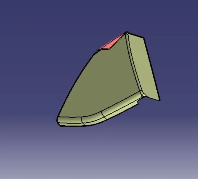
Bottle Holder :-
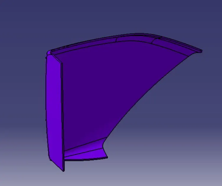
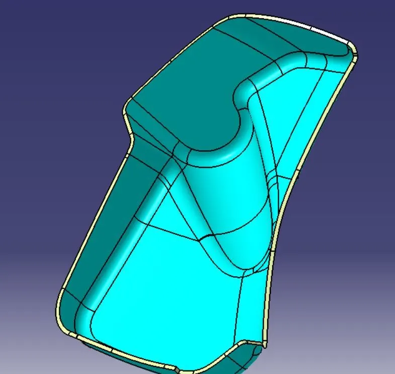
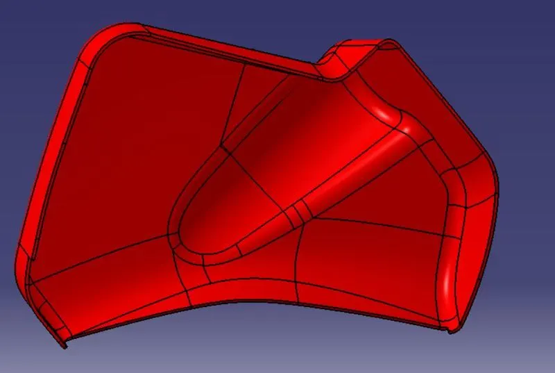
Class-C Surface Creation :-
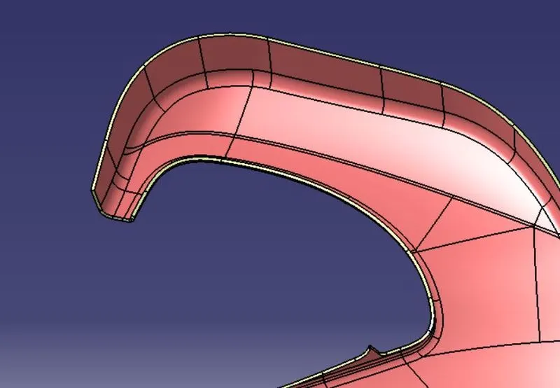
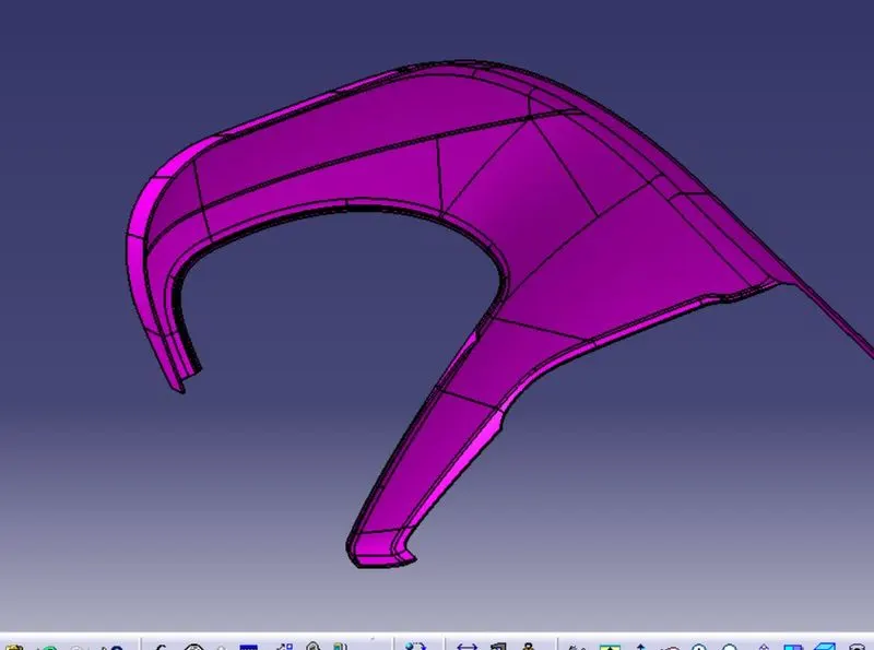
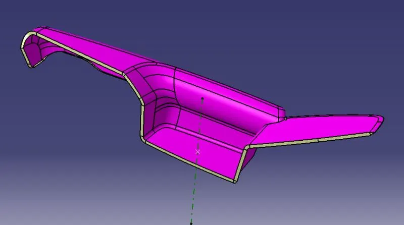
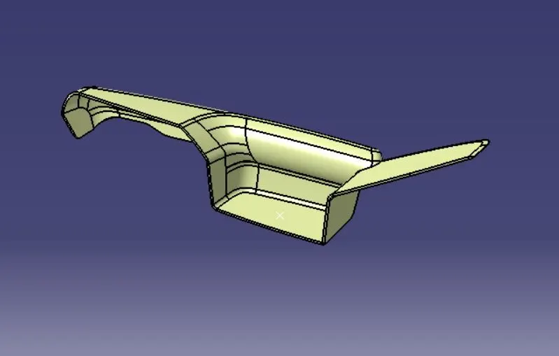
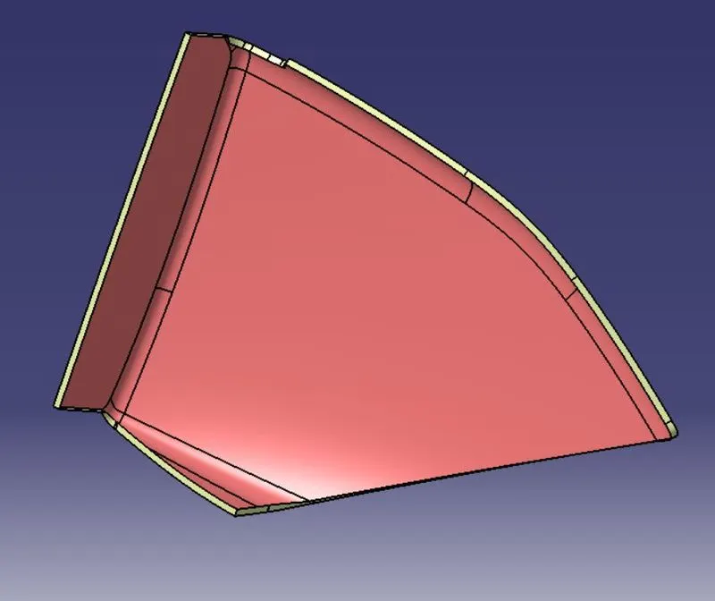
- The class C surface is the surface which is created to provide thickness to the class A surface with the help of class B surface.
- The class C surface is the middle portion of the class A and class B surfaces.
- The class C is created with the help of the sweep command in surface workbench.
- The class A surface's boundary is taken as profile (guide curve) and then tooling axis created is taken as direction of the sweep in subtype draft direction
- The draft angle for the sweep is 3 degrees.
- The attained sweep is joined with class A surface to obtain the class C surface.
- The final trim is obtained by trimming the class B with the class C surface.
- The final check to ensure the proper clossness of surface with the boundary command.
Lower Substrate :-
Arm Rest :-
Map Pocket :-
Bottle Holder :-
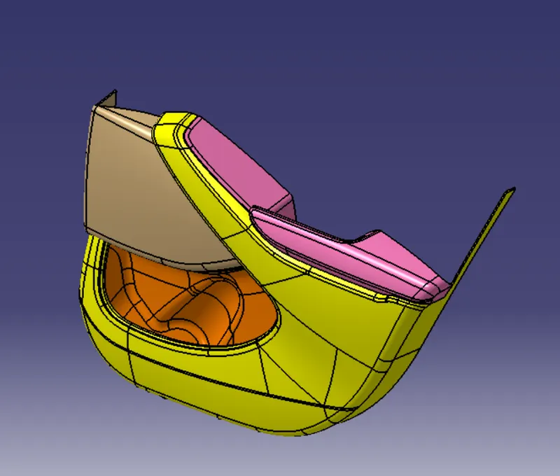
Create the Closed Surface Body :-
- Move to the part window and with the help of surface based feature close the surface to get the closed part body.
- Follow this for all the components.
Creatting The Attachment Features Using Master Section :-
Heat Stakes :-
- Heat Staking is a pulsed-heat process to join two or more parts out of which one at least is made of plastic.
- The process is to deform the plastic material using heat and force at a set process time.
- The bond is made by partially de-forming the plastic part in order to fix the other.
- Heat Staking makes it easy to bond metal to plastic and is commonly used in high volume/low cost applications such as automotive, IT and consumer appliances.
- Similar and dissimilar materials may be joined: metal to metal, plastic to plastic, metal to plastic
- Accurate control operating within a small process window
- Local heating resulting in no damage to surrounding materials
- Processing of glass-filled materials
- No mechanical vibration
- Many heat-stake shapes possible through custom designed tools.
Ribs :-
- The ribs provide economical stiffness and strength to the part without increasing the overall thickness of the part.
- The ribs are used as locating and arresting in the assembly as locators.
- Proper allignment in mating parts, slot and rib pair is long lasting other than screw pair which loosen up with time.
- Acting as stops or guide for mating the tilted headlamps.
- Rib designs includes.
- thickness, quantity, height , manufacturibility and location.
These are the some Screenshot of the Heat Stakes and Rib :-
Dog House :-
- Dog house is the attachment feature which helps you to assemble things at certain heights and also resolve the plastic defects.
- There are plenty dog house design which can be used for assembly purpose but we will be using the one provided to ous by the resources.
- The master section or the enginnering drawing must be followed for creating the dog house.
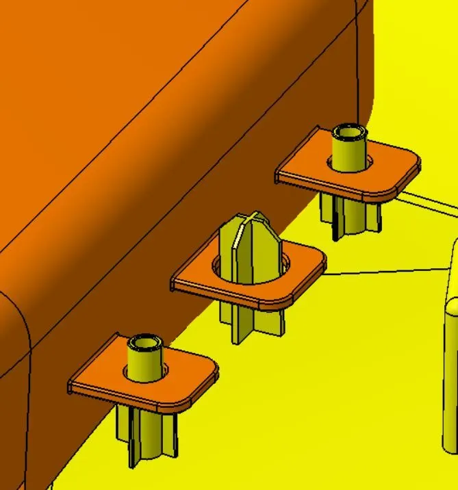
Push Pin :-
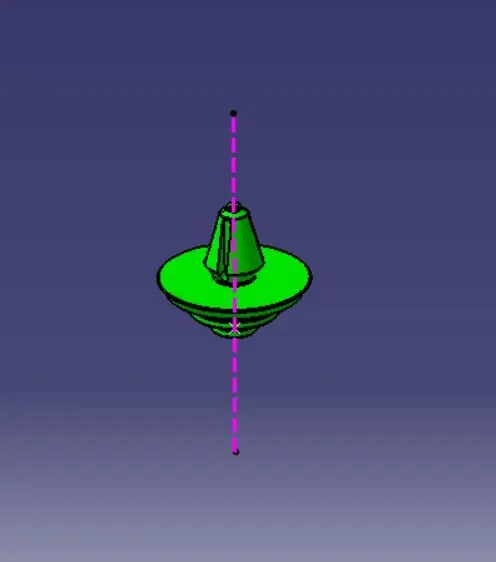
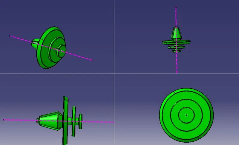
- These pins are used for the assembly purpose .
- These pins are guided into the sheet metal body.
- The pin is assembled over the dog house on one side and other into sheet metal.
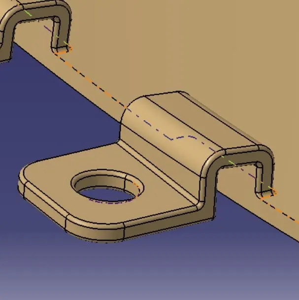
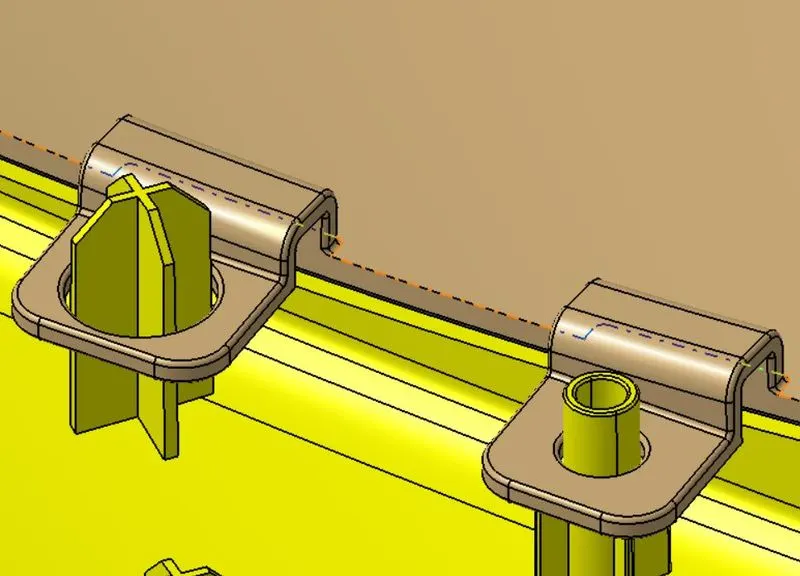
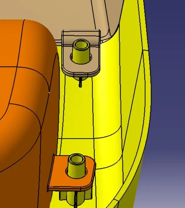
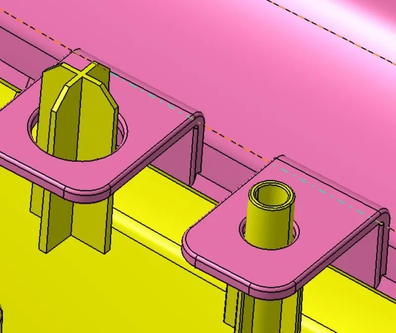
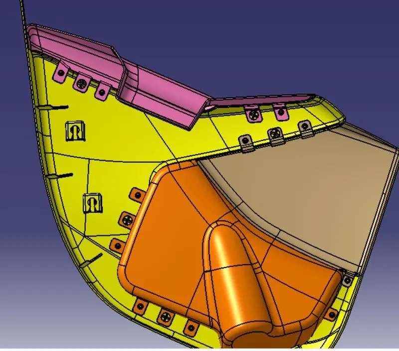
Flanges On The Component :-
- These flanges will be build on the components for the fittment purpose with lower substrate.
- The hole at center will be guided along the heat stakes.
- Later top portion of the heat stake will be melted over it.
- The flange should rest on the supporting ribs on side .
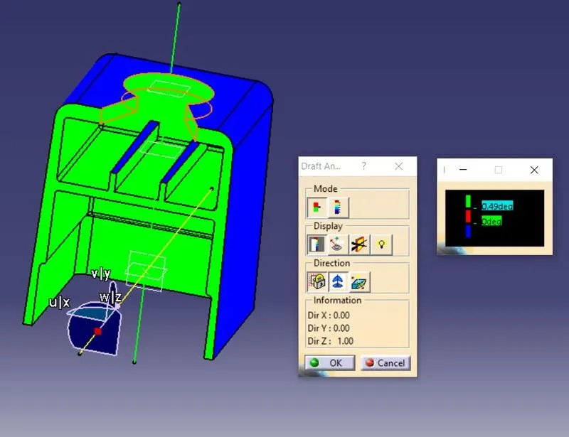
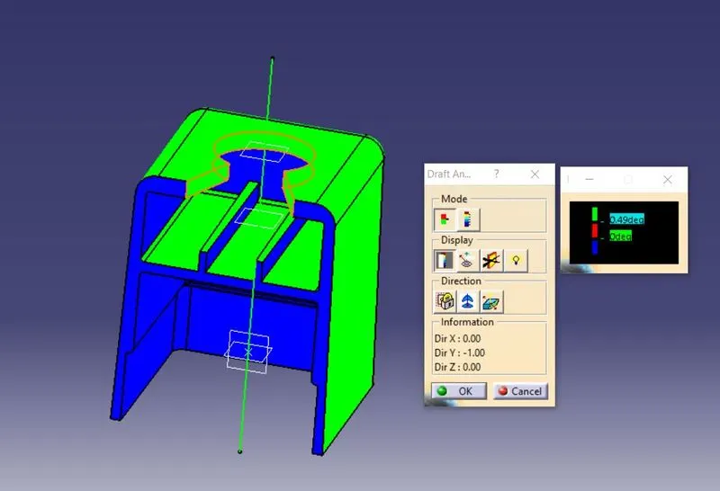
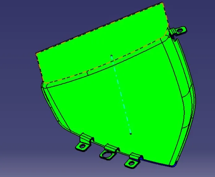
Draft Analysis Of The Component :-
- The draft analysis is done to ensure that the draft in permeasible with the design consideration.
- The draft analysis is done by changing the visualization mode to customize and select shading as material.
- The draft based feature enables us to visualize and examine the draft.
- The draft window is has two tables one is for examining the draft and other one is the colour code.
- The draft value is set in the colour code window with each colour having their own significance.
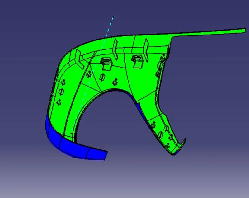
- The red colour indicates the positive draft less than minimum draft where as the green colour indicates the minimum draft.
- The blue colour indicates the negative draft.
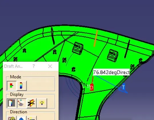
- For visualizing the draft the compass is aligned with the tool axis direction and the cursor is then made clicked upon the surface for viewing the draft.
- The quick view in display window enables to examine the draft value throughout the surface.
- Here both class A and closed body are given the minimum draft as 3 degrees.
- The attachment feature are given draft of 0.5 degrees.
Lower SubStrate :-
Dog House :-
Arm Rest :-
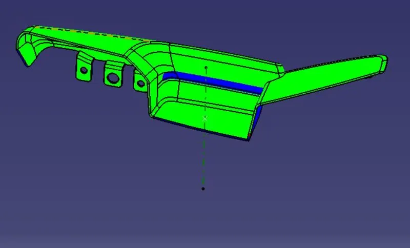
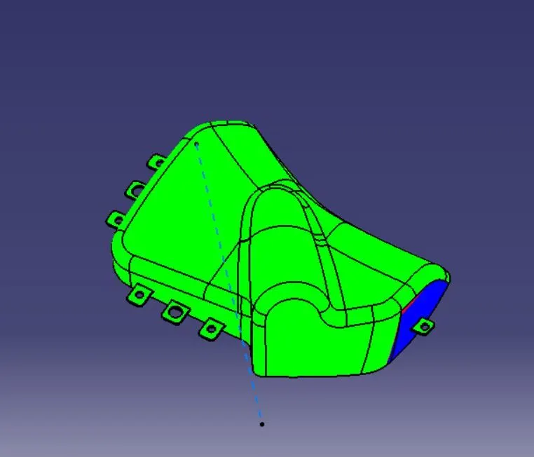
Here in the Arm Rest some area is not clearing the Draft angle this is due to the Class-A Surface, when we see such like of issue first inform to the Class-A surface team to rectify the Issue then improved the Draft angle otherwise it will create problem During Manufacturing.
Map Pocket :-
Bottle Holder :-
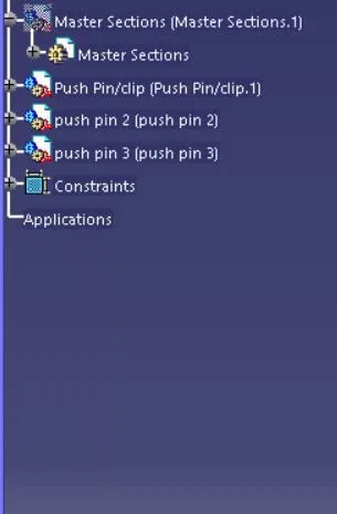
Assembly Constraint of Push pin Assembly over the Dog House :-
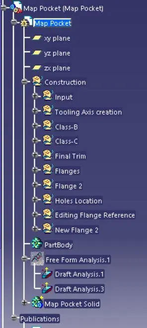
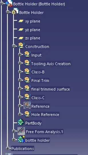
Tree Structure :-
Conclusion :-
Finally,the Interior trim of the Car interior door trim is designed using the given A Class Surface as the Input and B and C Class Surfaces are created with respect to the A Class Surface.