Week 11 - Final project
AIM:
To create a door interior part from the inputs of class A surface along with master section by following the design rules followed in tier 1 and OEM industries in CATIA v5.
STEPS:
- Check the connectivity of the Class A Surface. Ensure that there is no gap between the component, using join command check it or by clicking boundary command.
- Find the possible tooling direction for the given component, it is the direction of mould (core or cavity) opening and closing.
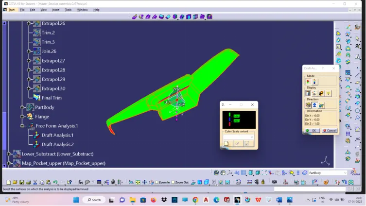
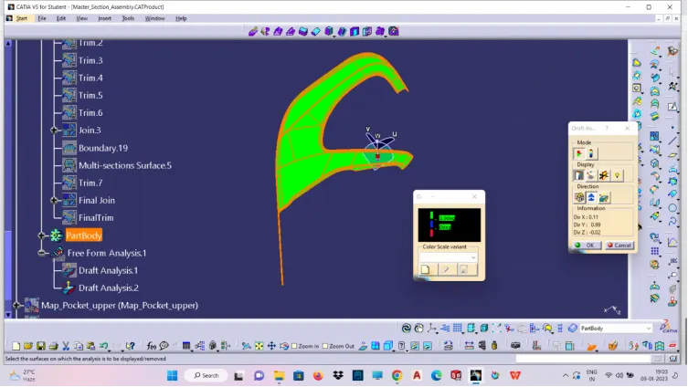
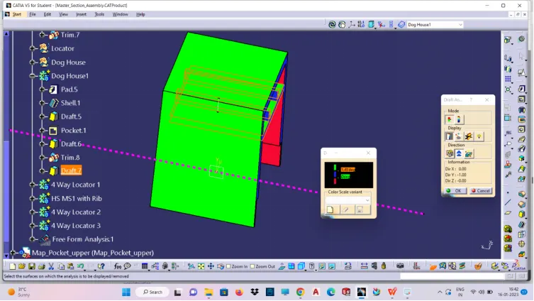
- Find THE DRAFT ANALYSIS, DRAFT IS required on all the parts in the direction of mould movement in order to allow parts to release (or) eject from the moulds properly
- DRAFT NOMINAL VALUE:3 degree is the nominal value,7 degree for textured faces
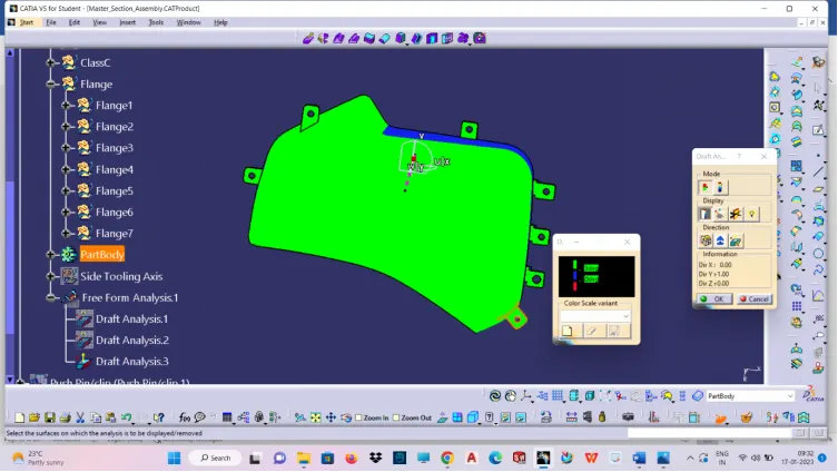
- colour ranges in draft analysis
green-draft above 3 degree
red-below 0 degree
blue-0 to 3 degree
Draft is providing angles or tapers on the product engineering features such as ribs, screw bosses, that lie parallel to the direction of release from the mould ease part ejection.
The draft is done based on the tooling direction.
CREATING TOOLING AXIS:
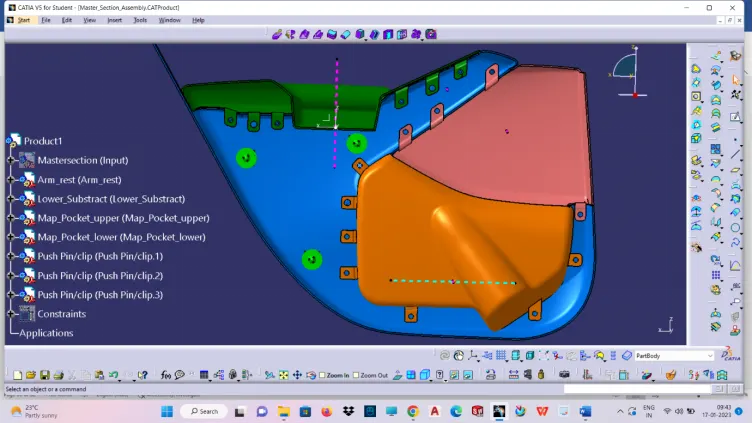
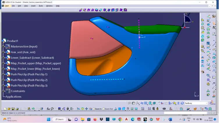
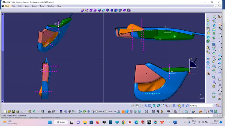
On the normal view of each and every component of door trim panel with respect to the created tooling axis , the tooling axis should clear all the area of the component. The tooling axis should designed in such a way. Tooling direction is the direction of mould opening and closing. In the below image pink coloured doted line is called main tooling axis.
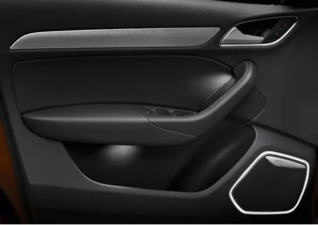
SOME OF THE COMPONENTS IN DOOR ASSEMBLY:
- Arm rest.
- Lower substrate.
- Map pocket upper.
- Map pocket lower.
- Push pin/clip.
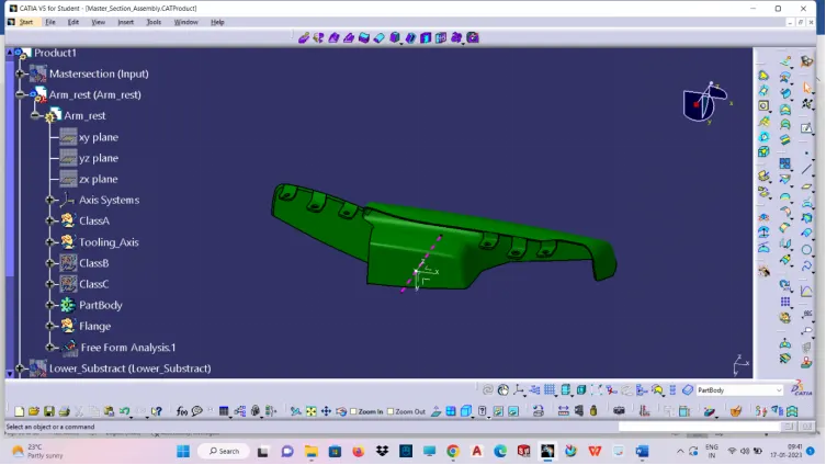
ARM REST:
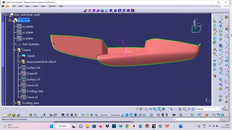
GIVEN CLASS A:
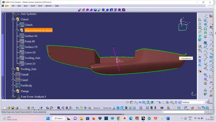
While performing or checking continuity in the given class A surface, it should be seem like a small discontinuity or patch on the surface.so we need to improve the surface quality of class A without doing any major modification.
IMPROVED CLASS A:
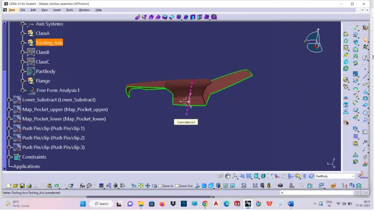
CREATION OF TOOLING AXIS:
The tooling axis is created by extracting a particular surface and place a point on the surface wherever required by point on surface method, then create a line through the point along the required direction(Z). The tooling must clear in all direction of class A, it should be created like that.
DRAFT ANALYSIS OF IMPROVED CLASS A:
CLASS B CREATION:
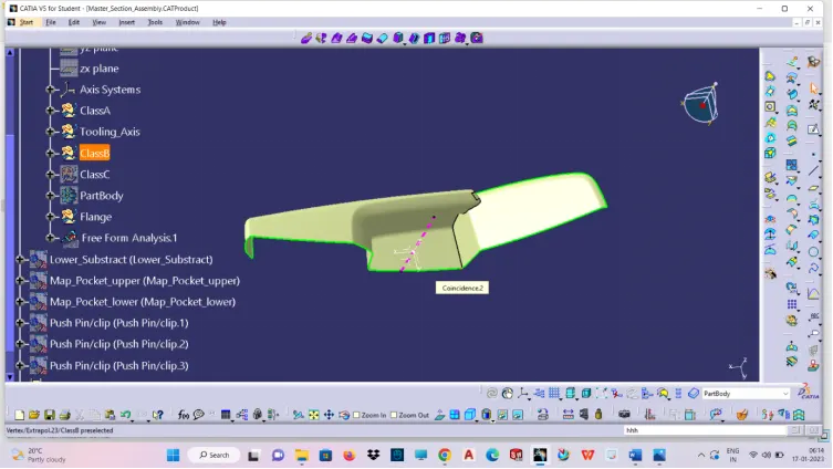
CLASS A AND B:
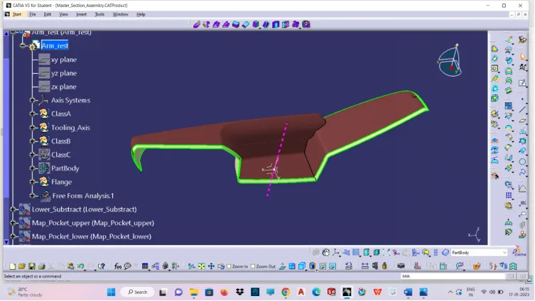
CLASS C CREATION:
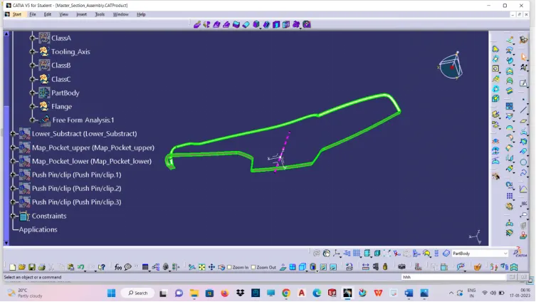
FINAL JION OF CLASS A & c:
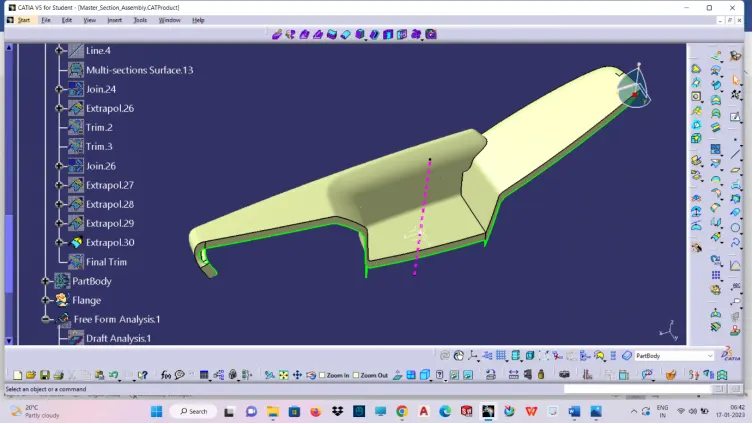
FINAL TRIM:
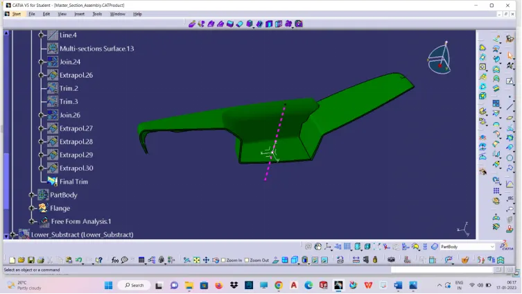
PART BODY OF FINAL TRIM:
DRAFT ANALYSIS OF PART BODY:
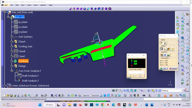
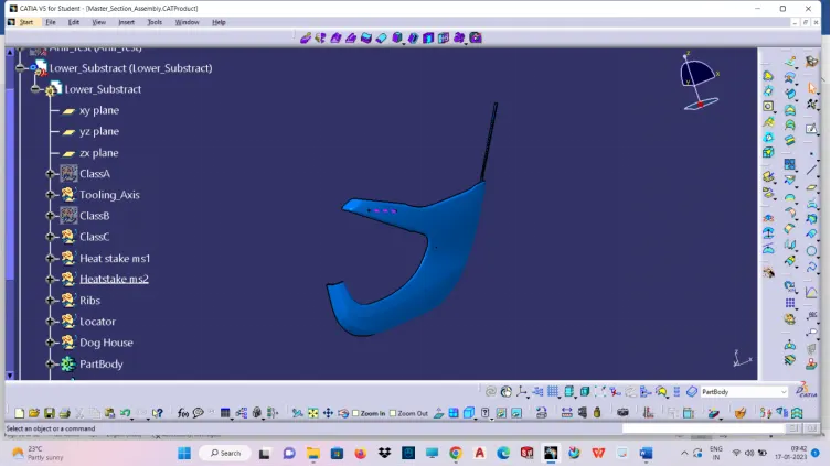
LOWER SUBSTRATE:
- Check the connectivity of the Class A Surface. Ensure that there is no gap between the component, using join command check it or by clicking boundary command.
- Find the possible tooling direction for the given component, it is the direction of mould (core or cavity) opening and closing.
GIVEN CLASS A:
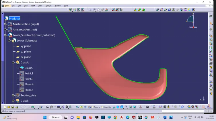
TOOLING AXIS:
The tooling axis is created by extracting a particular surface and place a point on the surface wherever required by point on surface method, then create a line through the point along the required direction(Z).The tooling must clear in all direction of class A and so it should be created in such a way.
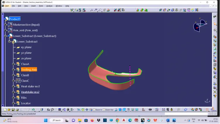
DRAFT ANALYSIS OF CLASS A:
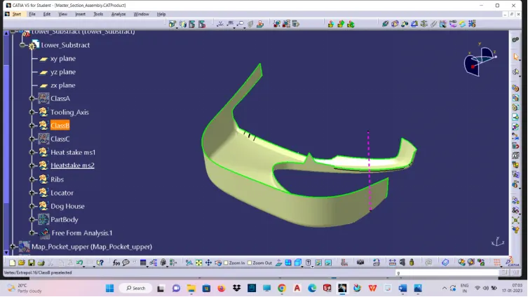
CLASS B:
CLASS C:
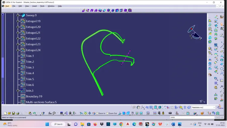
CLASS A & C JOIN:
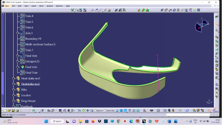
TRIM CLASS A & C JOIN WITH B:
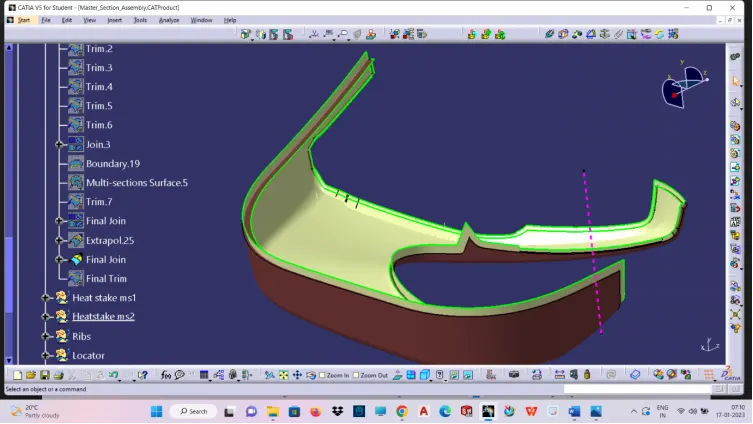
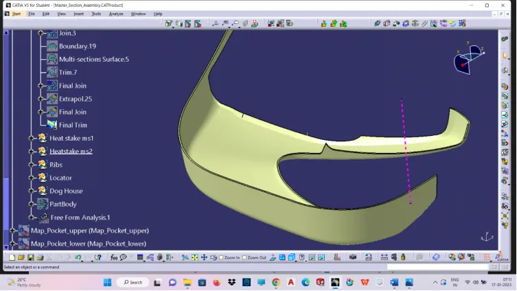
SKETCH FOR CREATING HEAT STAKE:
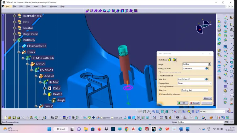
- Create a point wherever required and create a plane at that particular point by parallel through point option then make a positioned sketch at that created plane.
- Then insert body and pad it for appropriate distance as mentioned in master section by following the tooling direction. Then apply the draft with respect to tooling direction.
- Then make another sketch for creating ribs for heat stake then insert new body and pad it .
- Then apply draft, fillets as mentioned above.
- Then make union trim between heat stake and ribs
Then finally translate it wherever it required by translate option on the points already created.
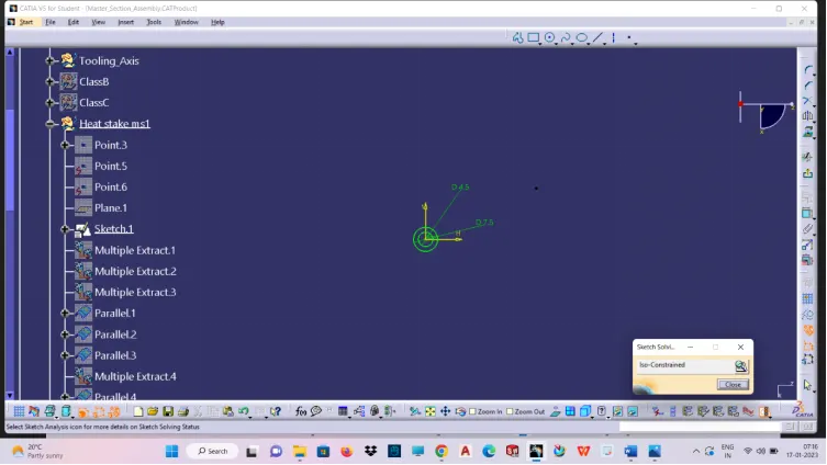
DRAFT APPLIED TO HEAT STAKE:
SKETCH FOR CREATING 4 WAY LOCATOR:
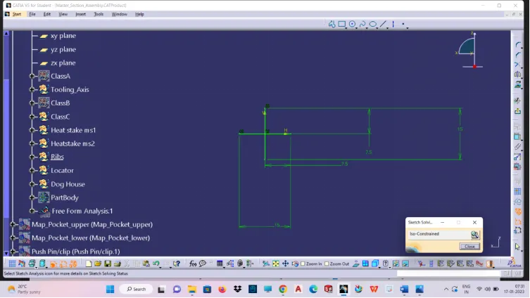
- Create a point wherever required and create a plane at that particular point by parallel through point option then make a positioned sketch at that created plane.
- Then insert body and pad it for appropriate distance as mentioned in master section by following the tooling direction. Then apply the draft with respect to tooling direction.
- Finally apply necessary fillets and chamfers and translate it wherever it required.
SKETCH FOR CREATING DOG HOUSE:
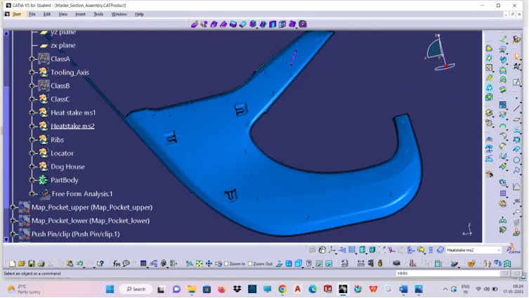
SKETCH FOR CREATING RIBS IN DOG HOUSE:

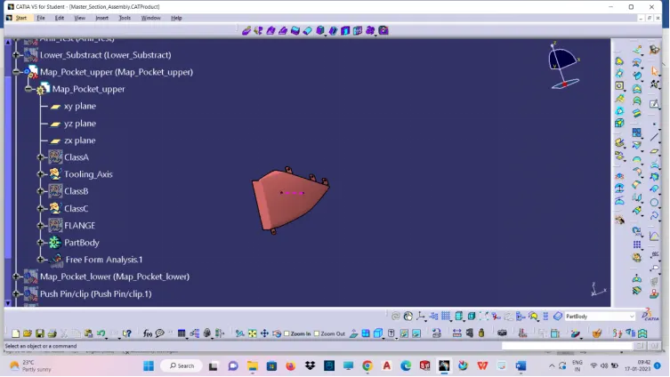
MAP POCKET UPPER:
- Check the connectivity of the Class A Surface. Ensure that there is no gap between the component, using join command check it or by clicking boundary command.
- Find the possible tooling direction for the given component, it is the direction of mould (core or cavity) opening and closing.
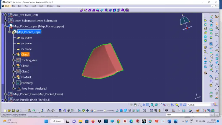
GIVEN CLASS A:
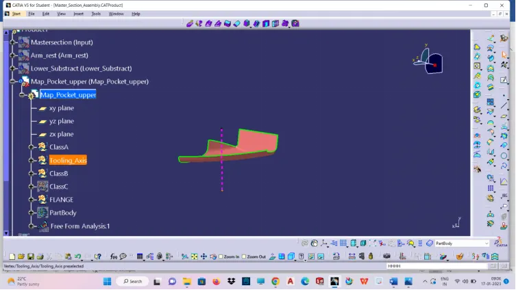
TOOLING AXIS:
The tooling axis is created by extracting a particular surface and place a point on the surface wherever required by point on surface method, then create a line through the point along the required direction(Z).The tooling must clear in all direction of class A and so it should be created in such a way.
DRAFT ANALYSIS OF CLASS A:
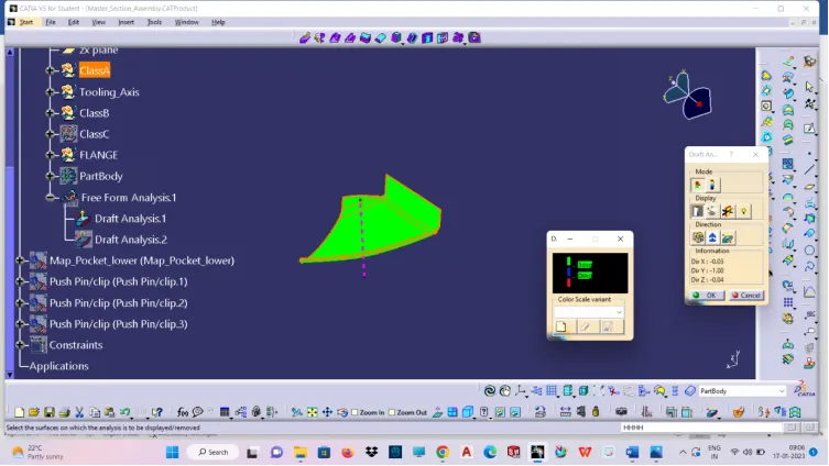
CLASS B:
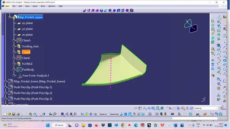
CLASS C:
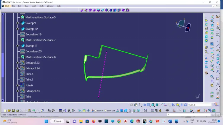
CLASS A & C JOIN:
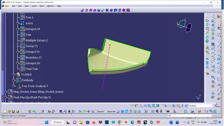
TRIM CLASS A & C JOIN WITH B:
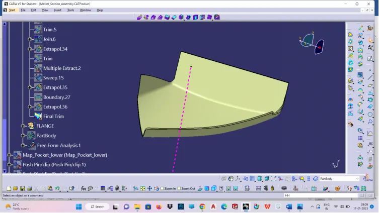
SIDE TOOLING AXIS:
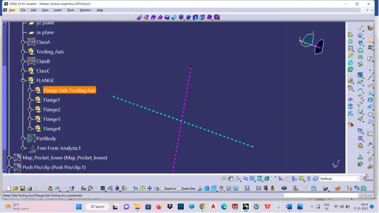
SKETCH FOR CREATING FLANGE:
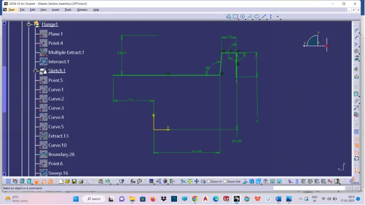
MAP POCKET UPPER WITH FLANGE:
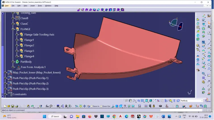
DRAFT ANALYSIS OF MAP POCKET UPPER WITH FLANGE:
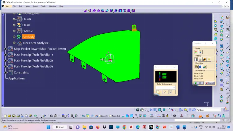
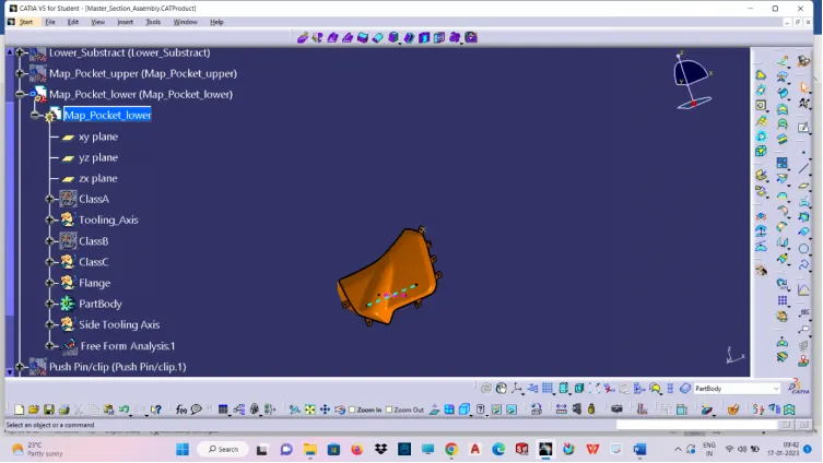
MAP POCKET UPPER:
- Check the connectivity of the Class A Surface. Ensure that there is no gap between the component, using join command check it or by clicking boundary command.
- Find the possible tooling direction for the given component, it is the direction of mould (core or cavity) opening and closing.
GIVEN CLASS A:
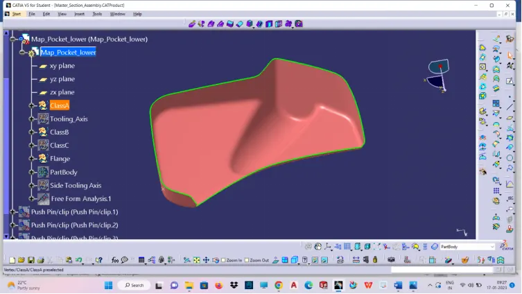
TOOLING AXIS:
The tooling axis is created by extracting a particular surface and place a point on the surface wherever required by point on surface method, then create a line through the point along the required direction(Z).The tooling must clear in all direction of class A and so it should be created in such a way.
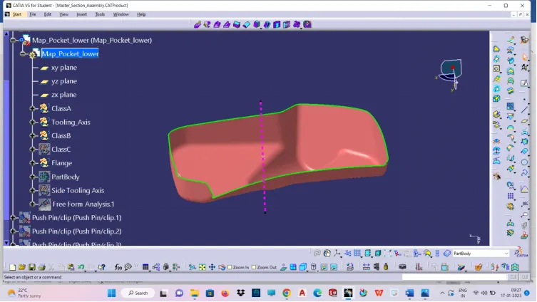
DRAFT ANALYSIS OF CLASS A:
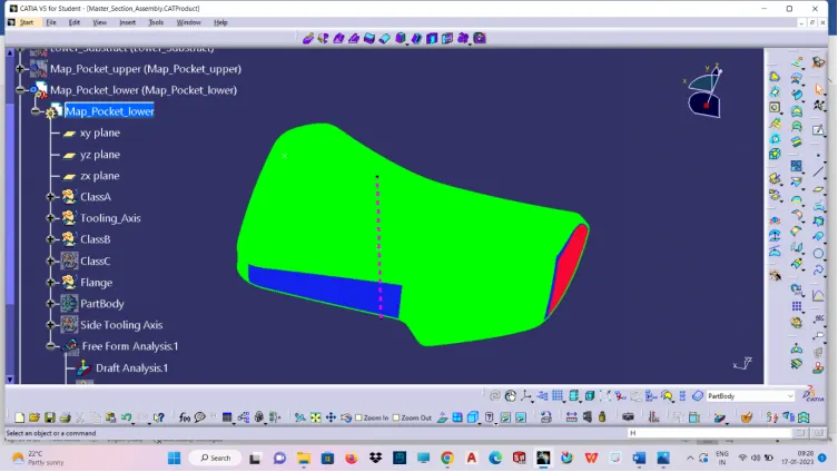
CLASS B:
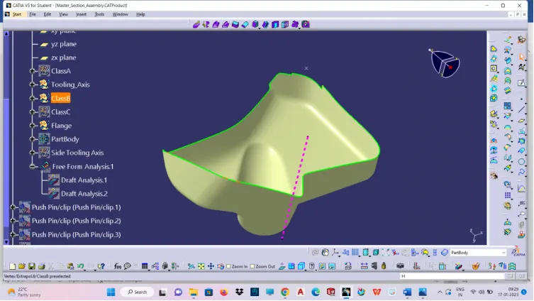
CLASS A & B:
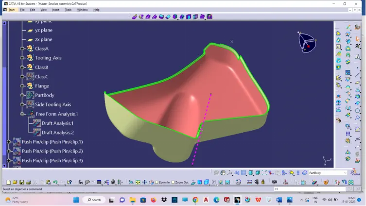
CLASS C:
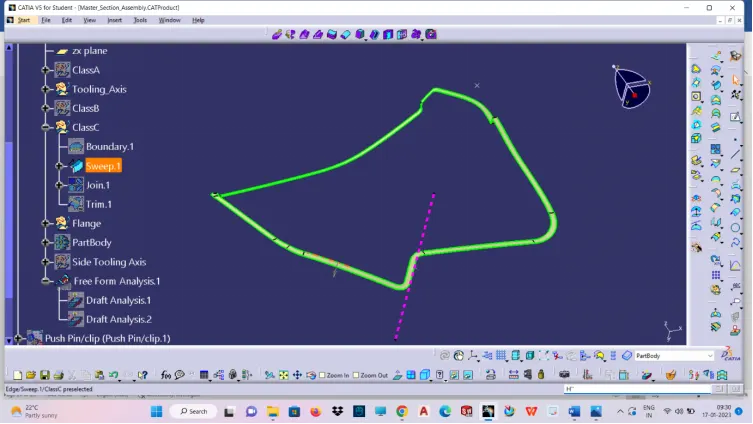
CLASS A & C JOIN:
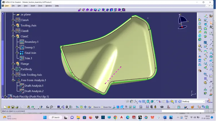
TRIM CLASS A & C JOIN WITH B:
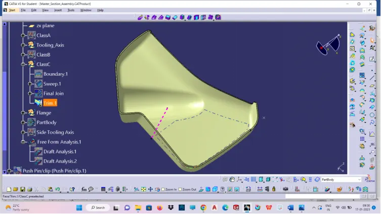
SIDE TOOLING AXIS:
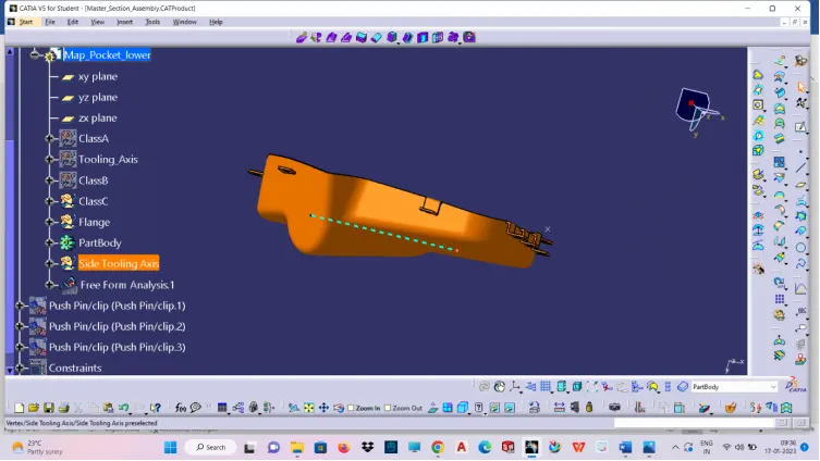
SKETCH FOR CREATING FLANGE:
- Create a point wherever required and create a plane at that particular point by parallel through point option then make a positioned sketch at that created plane.
- Then insert body and pad it for appropriate distance as mentioned in master section by following the tooling direction. Then apply the draft with respect to tooling direction.
- Finally apply necessary fillets and chamfers and translate it wherever it required.
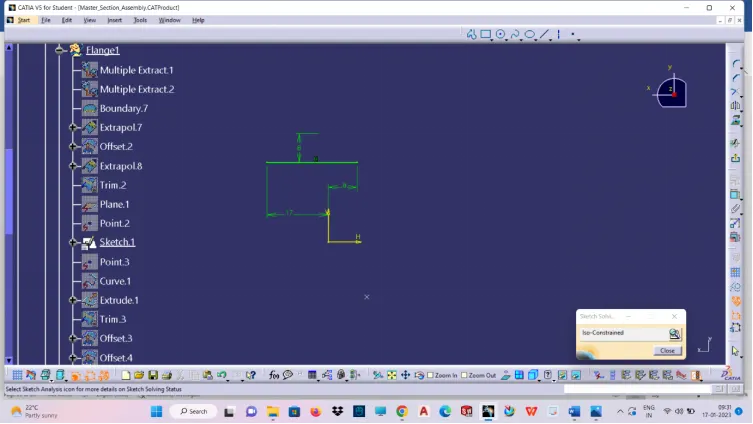
SKETCH FOR CREATING HEAT STAKE HOLE ON FLANGE:
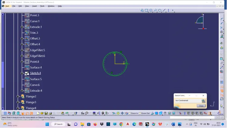
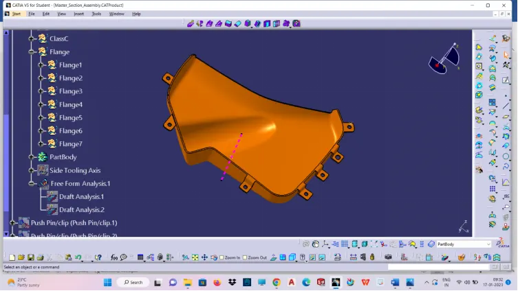
DRAFT ANALYSIS OF MAP POCKET UPPER WITH FLANGE:
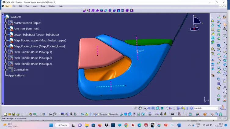
TREE STRUCTURE: