Week 11 - Final project
Aim: - Creation of CAD model (Car Door Inner Panel ) with reference to given class A surface by using a given master section, create attachment (Heat Stake, Ribs, Flanges etc…) and perform a draft analysis to check the manufacturing feasibility of the component.
Abstract: - The project deals with the explanation of steps and procedures followed while developing the Door Trim inner Panel of a car using CATIA V5. By Using a class A surface need tto create the Tooling Axis, Class B surface, Class C surface, and create a close surface component and after it need to create a close solid component after forming the close solid component from that I was able to create the flanges and the B side features such as Dog house, push pins, Heat stakes, etc. And finally, the draft analysis is also done on the components to check the manufacturability of the components.
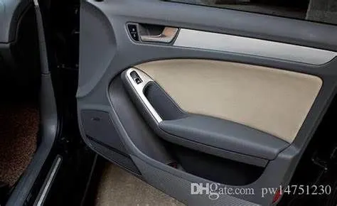
INTRODUCTION - The Inner Door Panel is an aesthetic and functional component in a car, it is the interface between the car interior and the inner working of door. Inner door panel usually consists of armrest, map pocket, bottle holder, handle bar, other switches, upper and lower substrate, storage compartments, convenience (puddle) lights and locking mechanism. Now days door panel is made of plastic material like polypropylene, ABS etc. which helps in making lightweight and complicated shapes of door panels.
The manufacturing Process of plastic door panel is called Injection moulding In this manufacturing process the heated molten plastic material is injected into the mould between core and cavity and cooled down to form a solid plastic component.
METHODOLOGY: -
- Check Surface Quality by Using Join/Boundary.
- Creation Of Tooling Axis.
- Do Draft Analysis on Class A.
- Creation Of Class B.
- Creation Of Class C.
- Create Close Surface By using Class A, Class B &Class C.
- Create Close Solid.
- Do Draft Analysis on Solid Component.
- Create B Side Features as Required.
- Do Draft Analysis.
INPUT GIVEN (CLASS A SURFACE & MASTERSECTION) :-
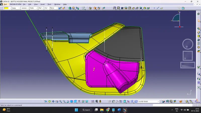
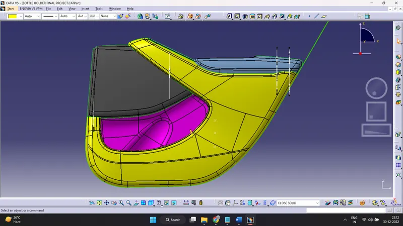
Since the Input Class A surface is containing four different parts. So Class B and Class C need to create for all the surface in separate CAT part. Also need to create tooling Axis & perform Draft Analysis separately. Finally, all the surface have assembled together in one CAD product.
Check Surface Quality & Direction of tooling Axis:-
- Check the surface quality by using Join/Boundary.
- A model should be enclosed and check surface continuity should be proper.
- Check all the boundary whether it has connected or not.
- Check the component Visually & analyse for best Tooling
Creation Of Tooling Axis:-
The next step is to create the tooling axis for the part which will determine the direction in which the core and cavity of the mould will move/open.
The mould is built in two separate pieces, basically. You have a Core side and Cavity side. The Core pulls apart from the Cavity and that's the Dye line or the Tooling Direction.
Designer must ensure that all holes and slots are covered in the main tooling and thus side core must be avoided whenever possible
After analysing visually for the best possible tooling axis, an axis system is created on the centre of one of the surfaces.
There are three Method For Creation of Tooling Axis.
- Point & Direction
- Normal to Surface
- Bisecting Method
For creating a tooling Axis Firstly Extract a surface and create a point on it.
1. Choose a line in Point & direction and Create Line It will First Tooling Axis.
2. Choose a Line in Normal to Surface And create line It will second Tooling Axis.
3. Create a line by using Bisecting Method and It will third Toolin Axis.
Select the Best one tooling Axis which is covering/clearing large area in draft analysis.
First of all analyse a component for best tooling axis
After analyse extract a one surface from class A.
By use that surface & create a point on it.
Use Line with point-Direction and create a line.
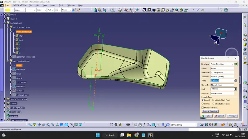
Use Line with Normal to Surface and create a line.
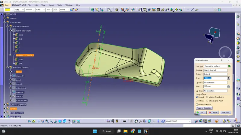
If our tooling axis is in Y direction then we need to find a tooling axis angle with X & Z Axis.
So Use a Bisecting method for it.
Firstly create a intersection from with class A and XY plane
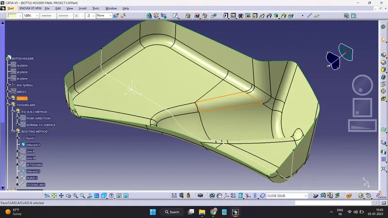
Now create a line in a intersection
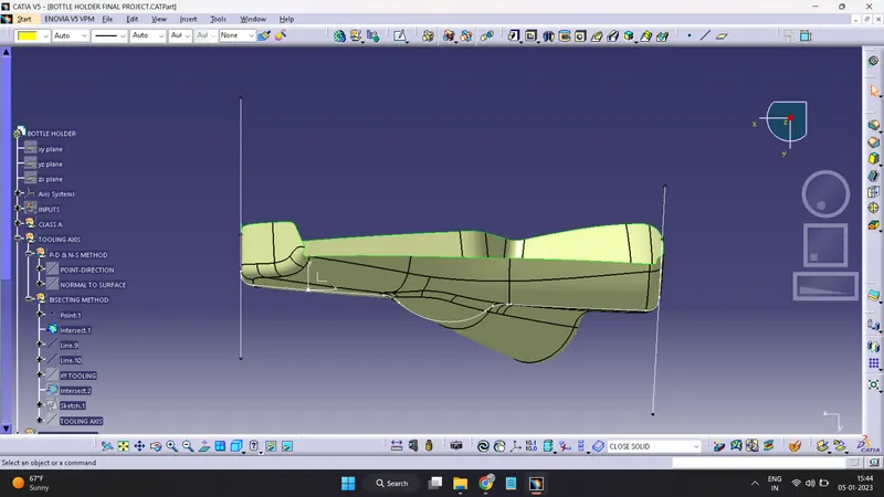
then create bisecting line of these two line. It will be XY plane tooling Axis.
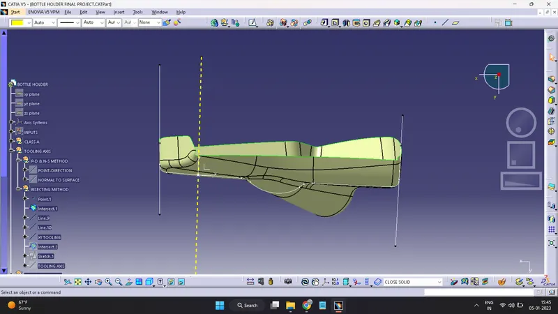
This same procedure needs to follow for YZ plane tooling axis
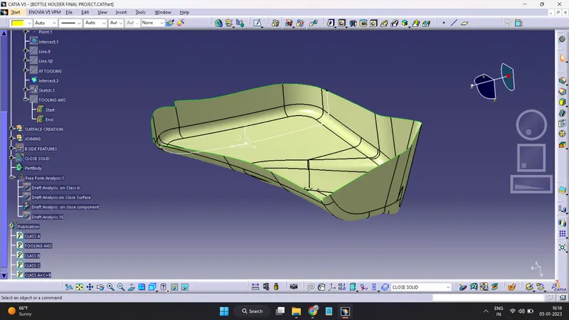
But this procedure isn't enough for getting a tooling Axis
So, now create a line by using Position Sketct with some angle.
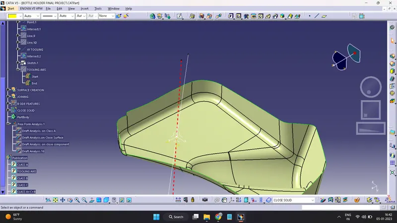
Now find the bisecting line between the both plane toolng Axis & It will bw final tooling Axis.
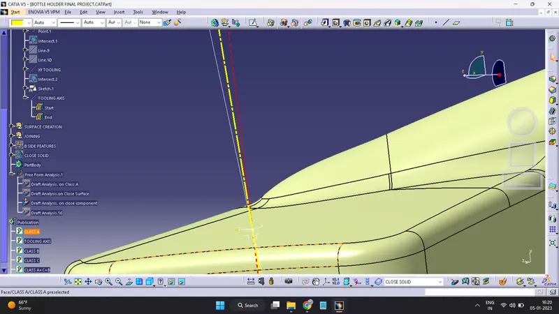
Tooling Axis For Bottle Holder:-
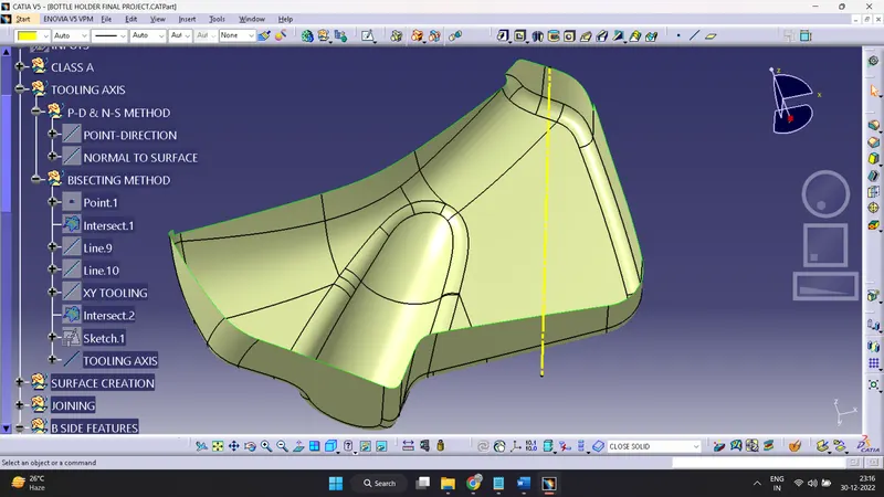
Tooling Axis For Lower Substract:-
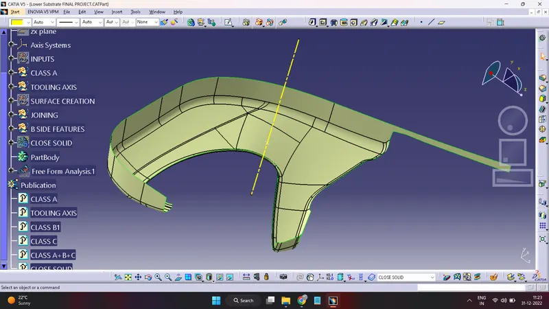
Tooling Axis For Map Poccket:-
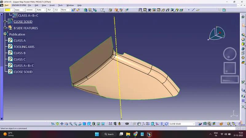
Tooling Axis For Arm Rest:-
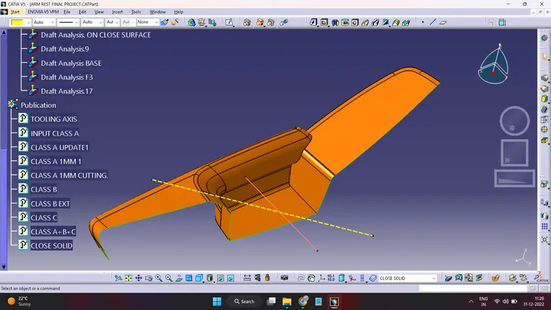
DRAFT ANALYSIS:
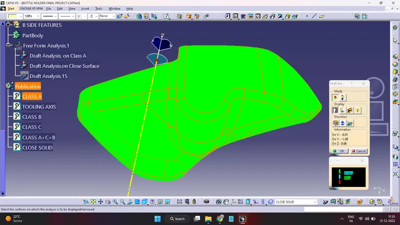
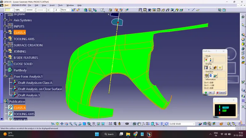
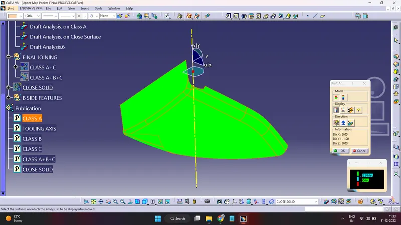
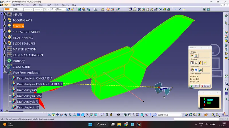
Draft analysis is done on the class A surface after the tooling axis has been obtained
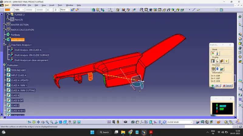
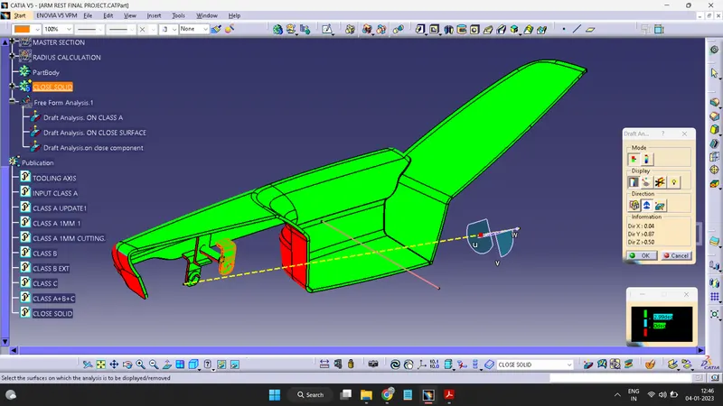
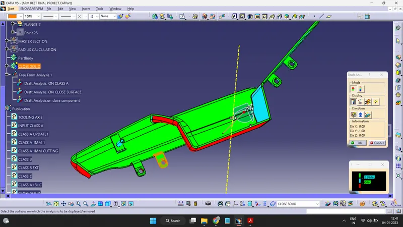
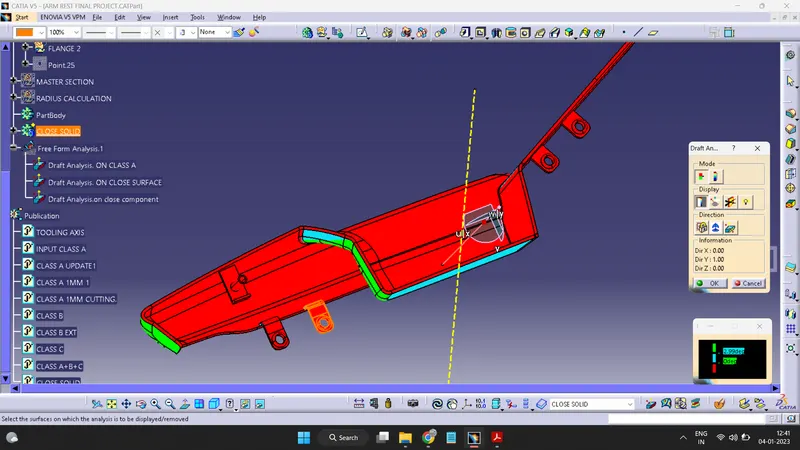
Draft Analysis command enables you to detect if the part you drafted will be easily removed or not. This type of analysis is performed based on colour ranges identifying zones on the analysed element where the deviation from the draft direction at any point, corresponds to specified values.
The part must have a minimum draft angle of 0.5degrees on all the tapered faces.
Using the feature draft analysis tool and the compass the part surface is validated for the minimum draft criteria
The Before going to drat analysis go to customized view parameter >under mesh >check material and then click ok.
Now for draft analyses go to insert » analysis » feature draft analysis.
Use the compasss to define the draft direction.
In the colour scale change the draft angle to 3 degree.
The component changes to green in indication of passing draft angle.
Use running point to check the angle on the component.
Draft Analysis For Bottle Holder:-
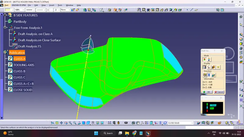
Draft Analysis For Lower Substract:-
Draft Analysis For Upper Map Pocket:-
Draft Analysis For Arm Rest:-
CLASS B SURFACE:-
After all the validation has been done, Check the thickness of the component by using a Master section. Class B surface is created by offsetting the class A surface to a distance of 2.5 mm
After offsetting many openings in the surfaces are found which are closed with the help of sweep, multi sections-surface, extrapolate tools etc…
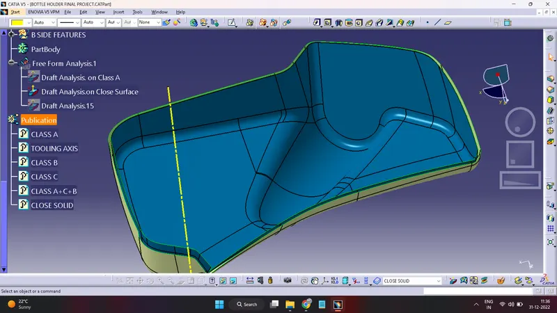
CLASS B SURFACE of Bottle Holder:-
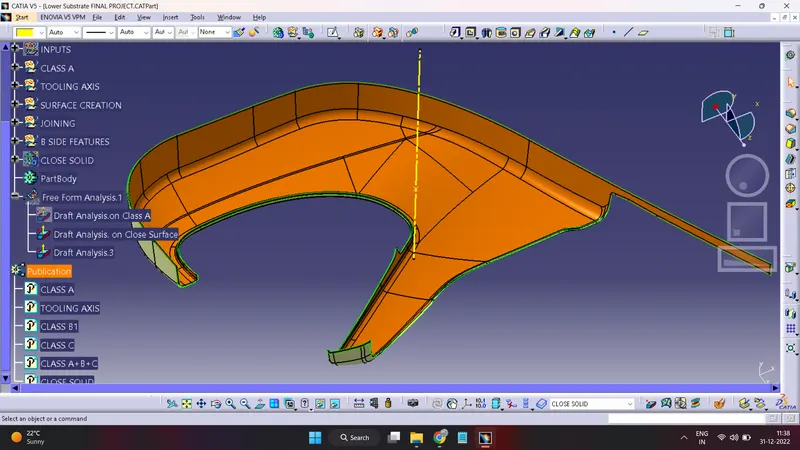
CLASS B SURFACE of Lower Substract:-
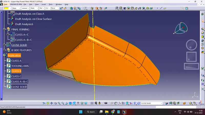
CLASS B SURFACE of Upper Map Pocket:-
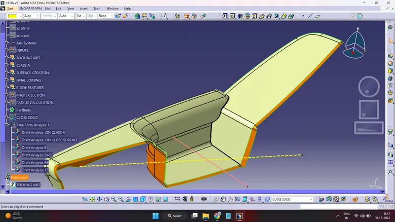
CLASS B SURFACE of Arm Rest:-
CLASS C SURFACE:-
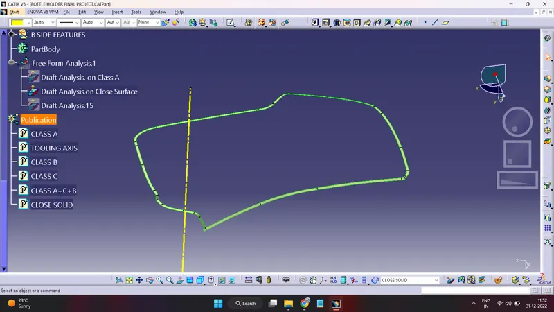
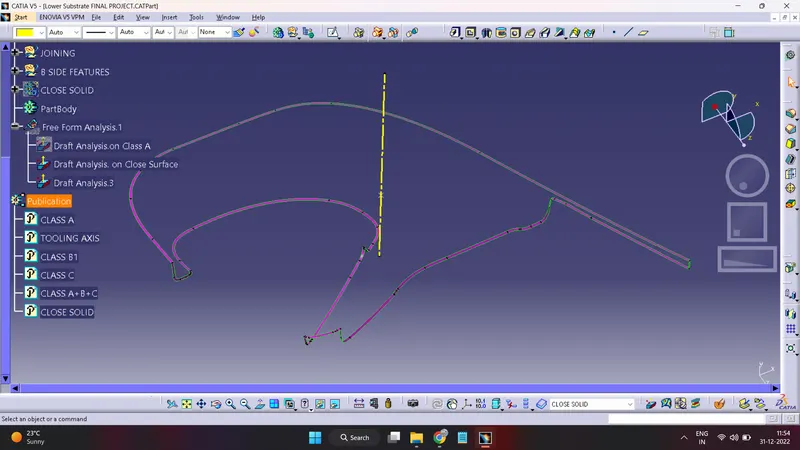
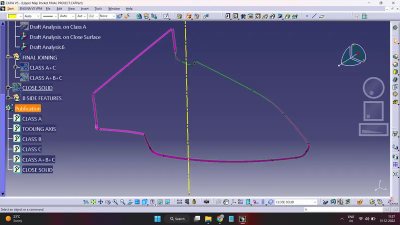
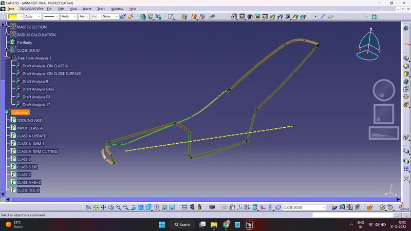
The class C surface which connects the class A and class B surface is created by using sweeping the boundary of the class A and it use the class A as a reference.
The sweep is divided into several parts in order to avoid complexity
Surfaces which are parallel to the tooling direction are swept with the tooling axis as reference and with a draft angle of 3degrees.
CLASS C SURFACE of Bottle Holder:-
CLASS C SURFACE of Lower Substract:-
CLASS C SURFACE of Upper Map Pocket:-
CLASS C SURFACE of Arm Rest:-
Joining of CLASS A, CLASS C & CLASS B
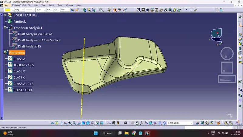
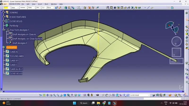
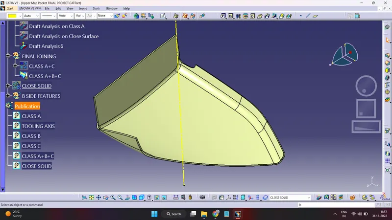
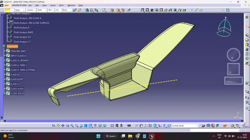
For creation of close surface component need to join of all the surface which are created.Firstly join the class A with Class C and after joining successfully trim it (Class A+ Class C) with Class B surface. And a Close Surface Component Created.
Final Close Surface Component of Bottle Holder:-
Final Close Surface Component of Lower Substract:-
Final Close Surface Component of Upper Map Pocket:-
Final Close Surface Component of Arm Rest:-
CREATION OF SOLID COMPONENT:-
goto Start>Mechenical Design> Part Design
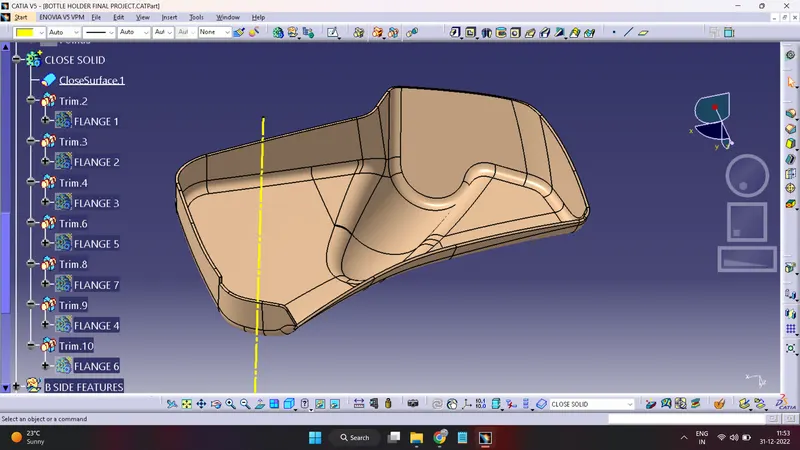
Surface Based Features> Close Surface> Select close surface>OK
& hide surface
Final Close Solid Component of Bottle Holder:-
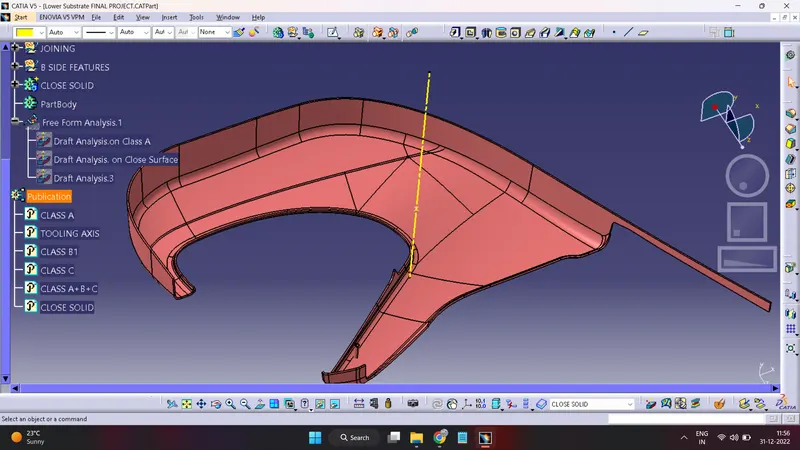
Final Close Solid Component of Lower Substract:-
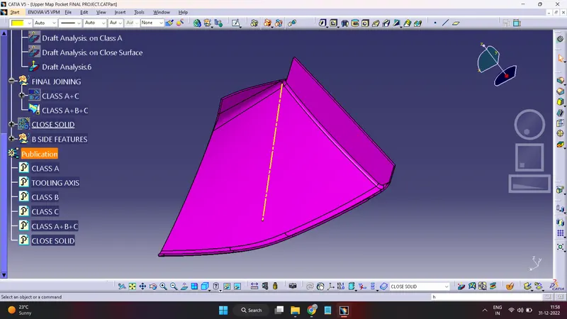
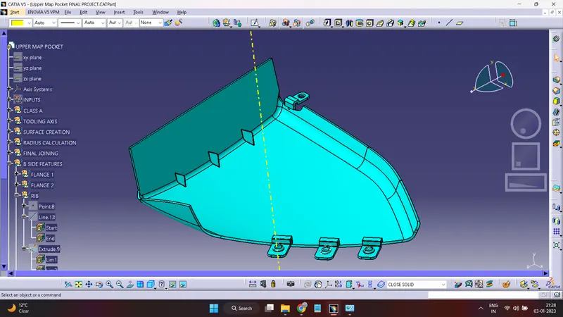
Final Close Solid Component of Upper Map Pocket:-
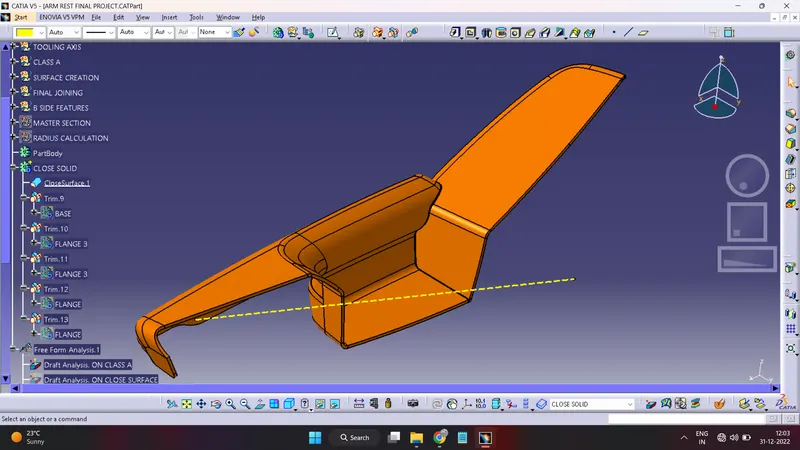
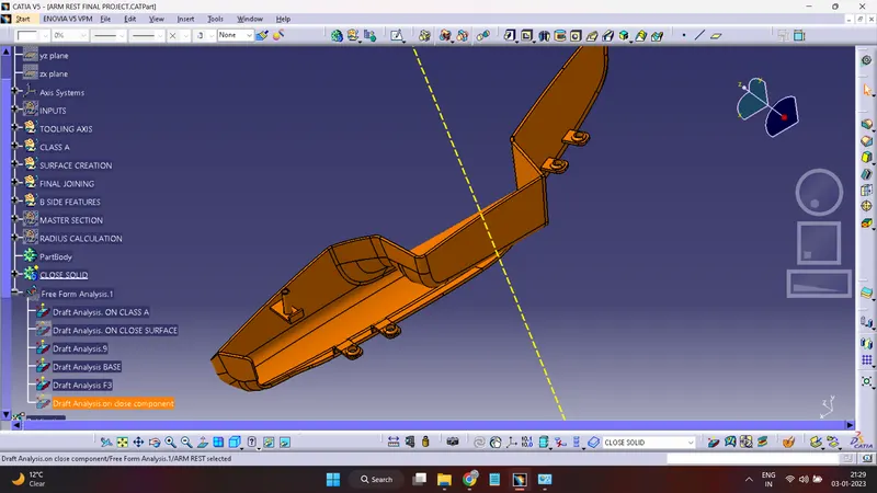
Final Close Solid Component of Arm Rest:-
B SIDE FEATURES:-
RIBS.
Ribs are indispensable functional structures on many plastic parts. It can effectively improve the rigidity and strength of plastic parts like the H beam. By using ribs, it is not necessary to greatly increase the wall thickness of the plastic parts, and ribs are not undercut structures like the H beam whose structure will be difficult to make for plastic injection molding. So ribs work well for plastic parts that are subject to pressure, torsion and bending. Ribs can also act as internal flow passages to aid in the plastic melt filling flow, which is of great help to the formation of complex and large plastic parts.
Ribs are generally designed on the non-appearing surface of the plastic part, and its direction is as close as possible to the flow direction of plastic melt filling. Ribs should neither be too long nor too thick, otherwise, it will increase the difficulty of injection molding, causing problems such as voids and sink marks on the back.
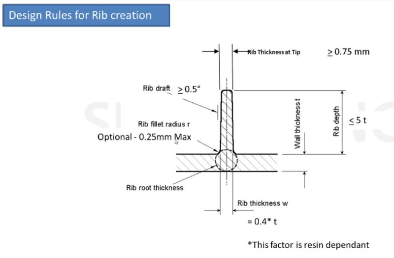
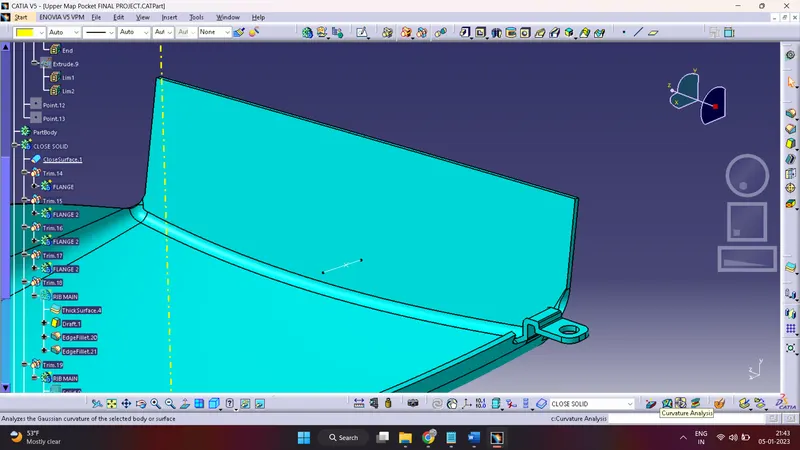
Creation of ribs:
create a line on surface by using Normal to Surface line Method
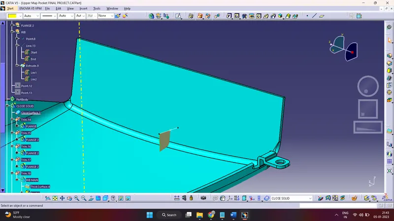
Now use Extrude and extrude it with design Rules
Use a thicken tool for provide thickness
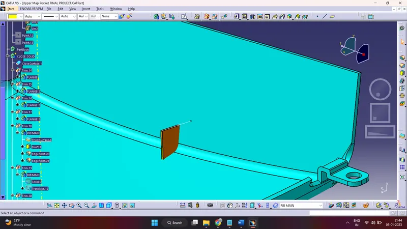
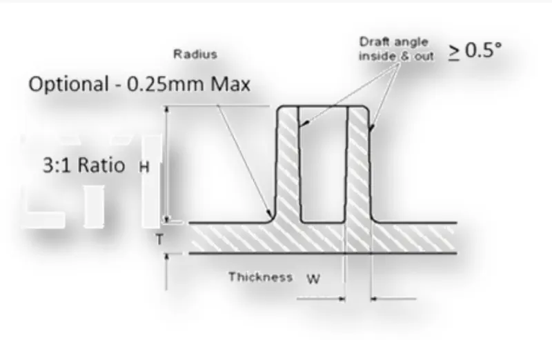
Make a Draft of 0.5 degree in all side
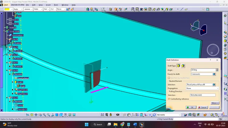
Fillet the Corners
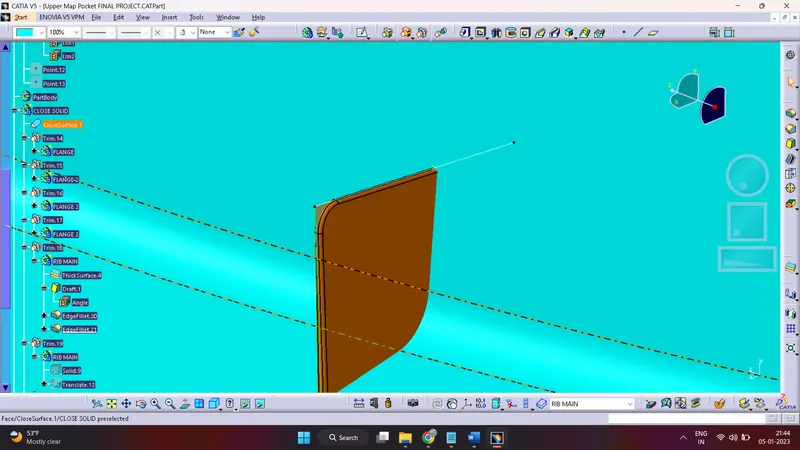
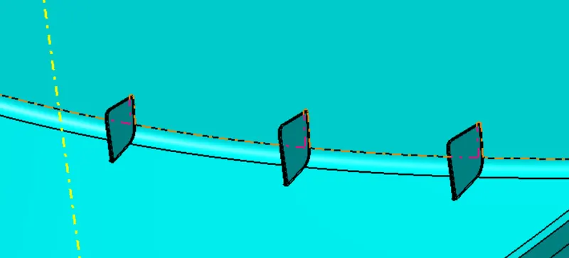
Rib Hase been Created...
Screw bosses:-
They are used to aid in the assembly of molded parts by providing a channel for a screw. Designing plastic screw bosses is fairly straightforward but there are a few considerations to ensure a strong connection between parts and mitigate cosmetic defects.
bosses are typically used to assist in assembly, as a receptacle for a screw or threaded insert or as the locator for a mating pin on another part. Because of its function, a boss must have sufficient strength to do its job. This dictates a minimum size for the feature.
Heat Stake:-
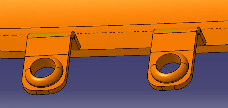
Heat staking also known as thermoplastic staking is the process of joining two dissimilar materials together. In heat staking we use local heating and cooling to raise the temperature of plastic components and allow plastic reforming to be carried out. This reforming can be used in a wide variety of applications.
Applications range from staking plastic bosses for assembly of car door panels to joining PCB’s to plastic housings. Benefits of this technique include; no vibration damage, no particulates, the ability to stake metalized coated applications and the capability to stake in difficult to access or restricted areas.
Industry Applications
Automotive : Reliable solution for interior parts, welding bumpers, tail light assemblies, dashboards & many more parts
Textile : Creates durable seals without the need for glues, clips and yarns in product designs
Appliances : Component welding for large or small household appliances
Creation of Heat Stakes:-
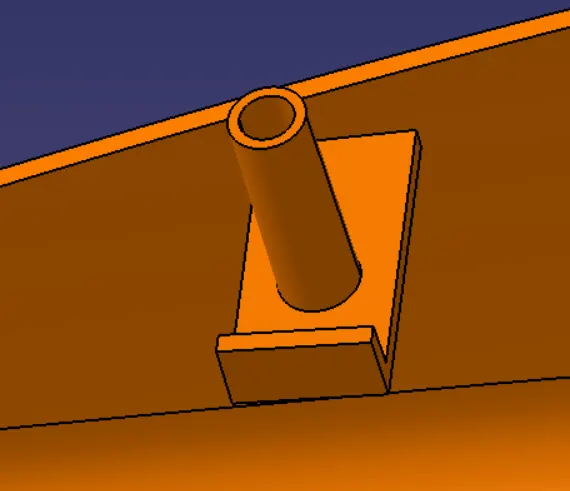
Select a surface where heat stake need to be created, Extract the Surface and create a point
Use a position sketch for create a sketch
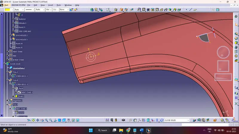
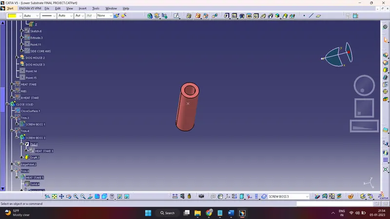
do pad on sketch
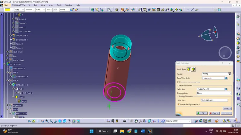
do a draft of 0.5 degree in both inner and outer sude of heat stake
Heat stake has been created
Locators:-
Locators provide a positive stop for the workpiece. Placed against the stop, the workpiece cannot move. Clamps, on the other hand, rely only upon friction between the clamp and the clamped surface to hold the workpiece. Sufficient force could move the workpiece.
- Locators are use to arres the degree of freedom , If it a xy,yx based component we will able to arres the x,y freedom
- we are having 12 number of degree of freedom so using of locators to lock it.
- It is having two different types ,they are two way locator and four way locator.
4 way locator:-
A round locating pin located concentrically in a hole is a common application of a 4-way pin, and helps to further secure the piece. 4-WAY LOCATORS: 4-way mean you prevent movement at 2 axes (+X, -X, +Y and -Y) on the plane. Generally, you have cylindrical pin on the fixture and circular hole at workpiece part.
2 Way Locator:-
A 2-way locating pin restricts motion along 1 axis (or 2 degrees of Freedom), like a round pin in a slot. Likewise, a 4-way pin restricts 4 degrees of freedom along 2 axes.
Dog House:-
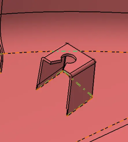
Dog house is an engineering feature used in plastic trim design. Dog houses are used as supporting feature. Sometimes other engineering features like snaps; locators etc. are mounded on them to increase their strength. Dog houses are subjected to draft analysis to prevent breakage of the component during ejection from mould cavity. Dog house and other engineering components are built on B-surface.
Design Rules:-
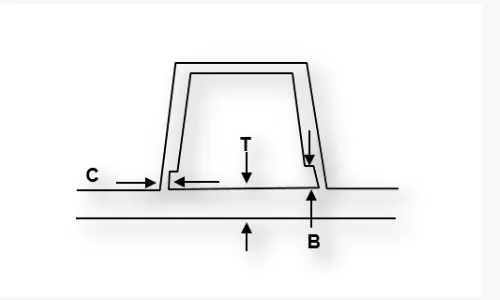
"C" is where the doghouse contacts the backside of the surface
-
Doghouse wall thickness at the intersection of the part wall ( C ) should be 40% or less than the main wall stock ( T ).
-
The height of ( B ) should be between 3.0 – 6.0 mm
By using all the design rules need to create all the B Side Features is close solid component.
CREATION OF Dog house
- Extract the surface that we going to create a dog house
- Insert a axis system. use positioned and draw a dog house sketch
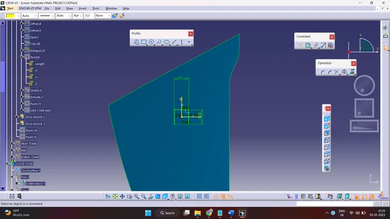
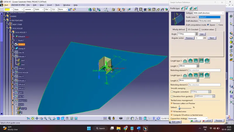
- Sweep the sketch to 1.5 degree on the direction of main tooling axis
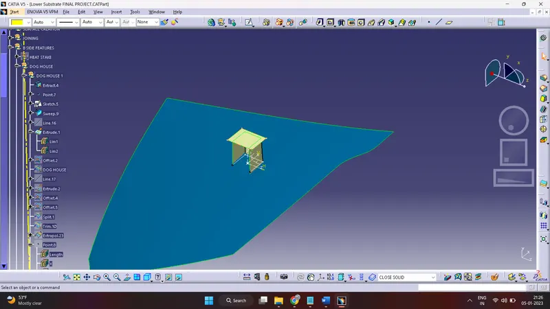
Create surface for upper part
offset it with Some Distance
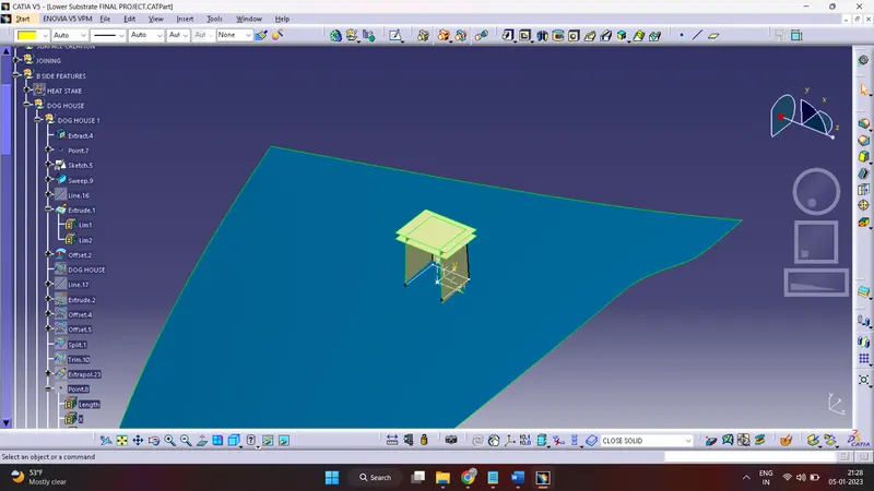
Trim the surface and remove unwanted surface
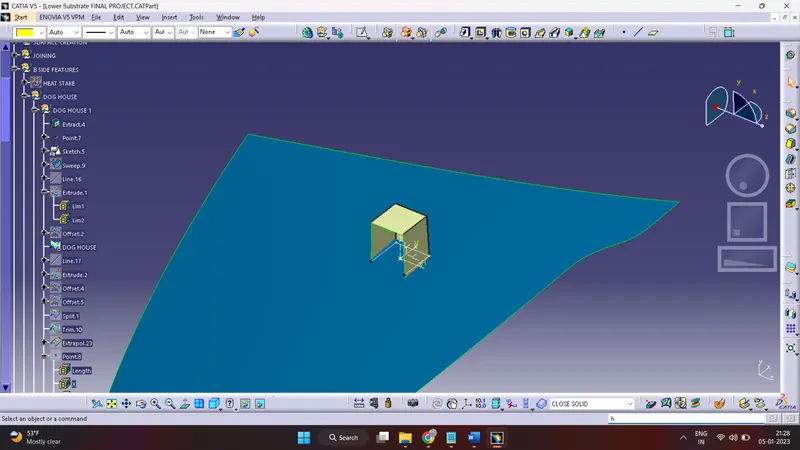
Use a thicken for create thick solid dog house
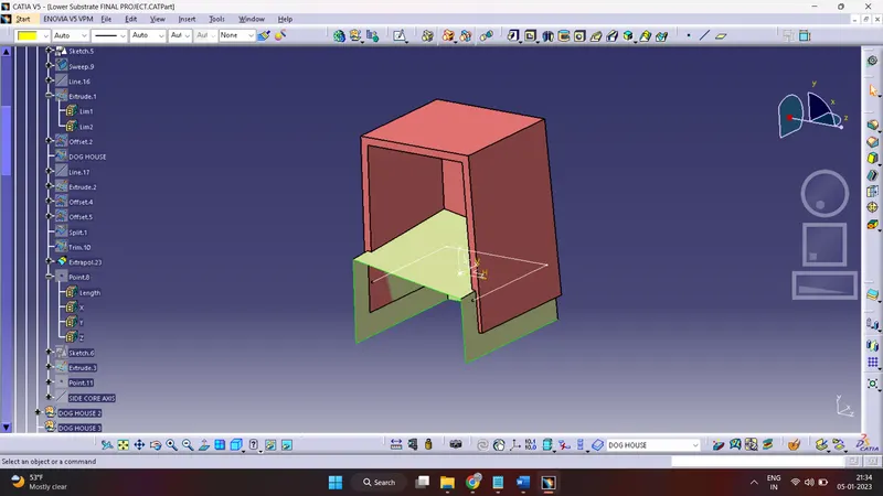
Now need to create a Sink Saver with Design Rules & by offseting doghouse Surface & Base Surface
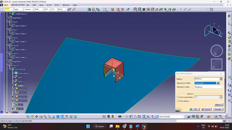
After creation of it give fillet in both side

Create a Sketch on top of Dog House for Key Holder/Push Pin Holder
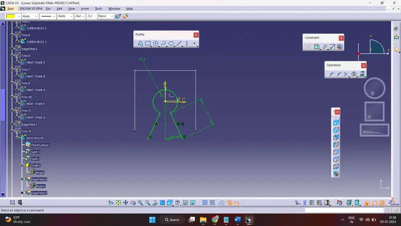
Split for remove remaining part
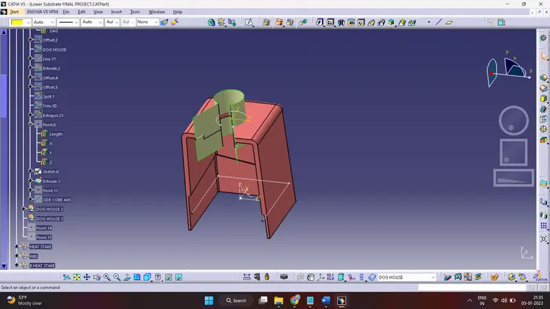
And Dog House Has Created......
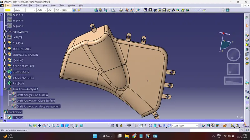
Final Close Solid Component with Engineering Attachment Features:-
Bottle Holder
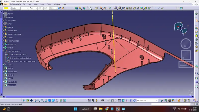
Lower Substract
Upper Map Pocket
Arm Rest
Attachment Features:-
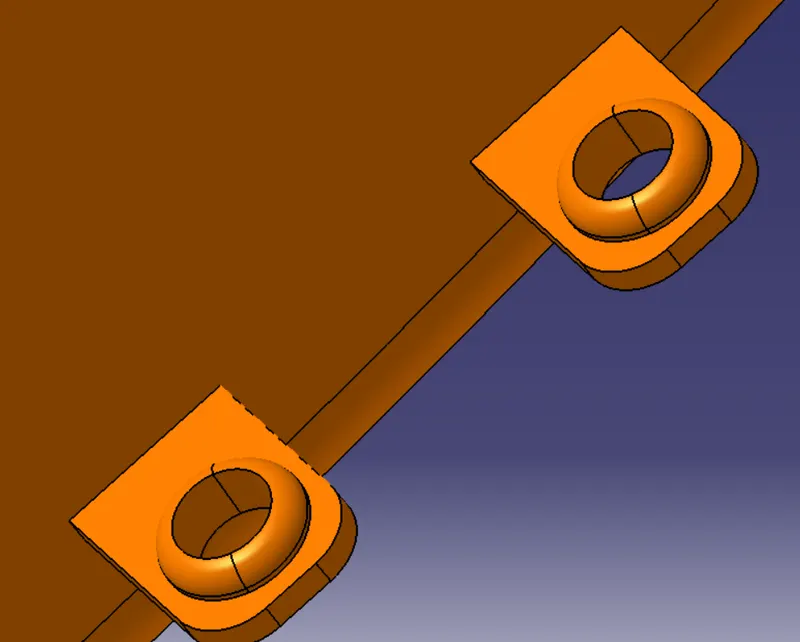
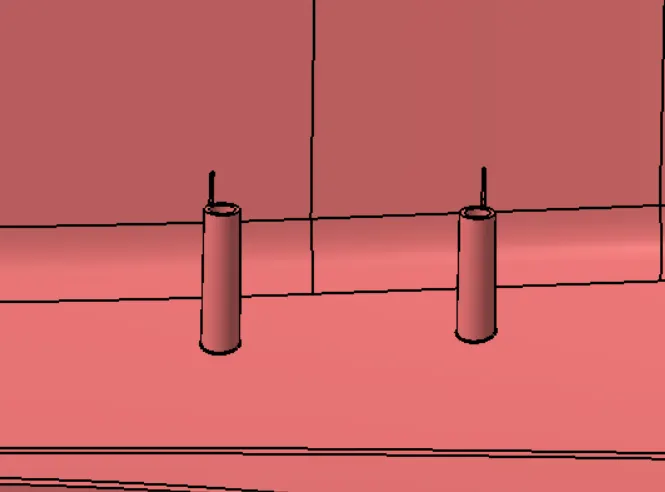
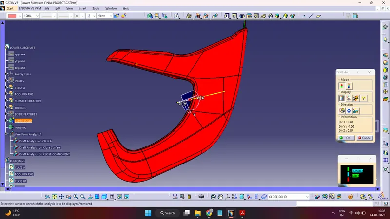
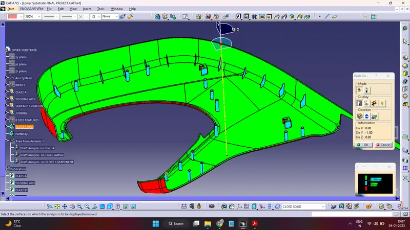
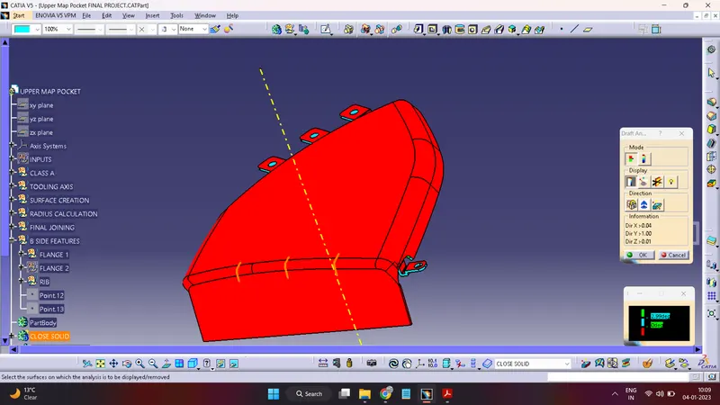
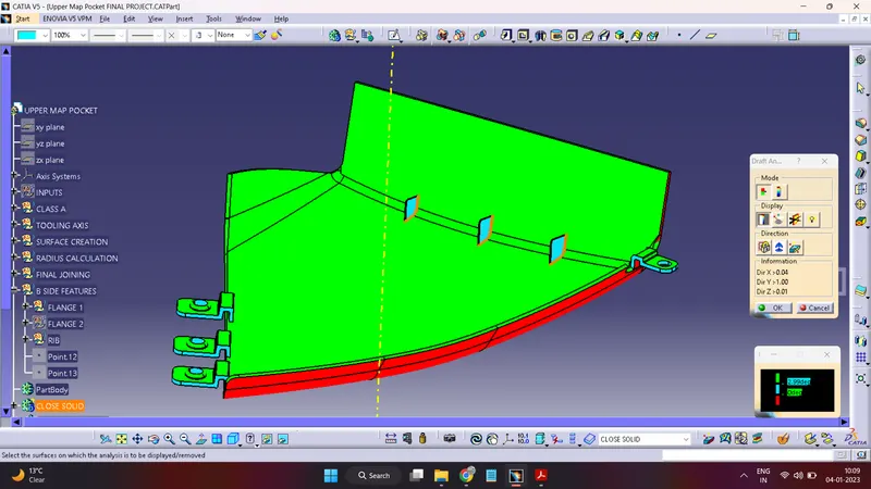
DRAFT ANALYSIS:
Draft analysis need to be done on close solid with attachment features.
Draft Analysis command enables you to detect if the part you drafted will be easily removed or not. This type of analysis is performed based on colour ranges identifying zones on the analysed element where the deviation from the draft direction at any point, corresponds to specified values.
The part must have a minimum draft angle of 0.5degrees on all the tapered faces.
Using the feature draft analysis tool and the compass the part surface is validated for the minimum draft criteria
The Before going to drat analysis go to customized view parameter >under mesh >check material and then click ok.
Now for draft analyses go to insert » analysis » feature draft analysis.
Use the compasss to define the draft direction.
In the colour scale change the draft angle to 3 degree.
The component changes to green in indication of passing draft angle.
Use running point to check the angle on the component.
Draft Analysis For Bottle Holder:-
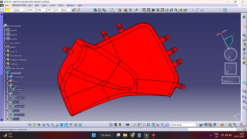
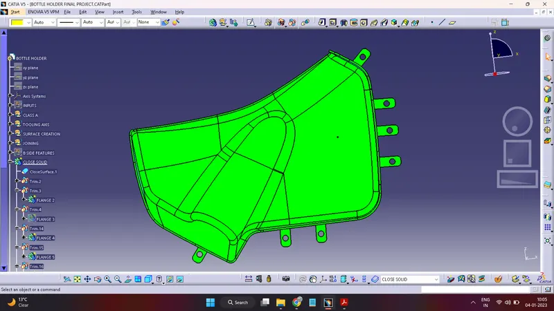
Draft Analysis For Lower Substract :-
Draft Analysis For Upper Map Pocket:-
Draft Analysis For Arm Rest:-
FINAL DOOR TRIM COMPONENT WITH DIFFERENT VIEWS:-
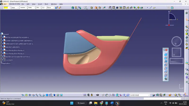
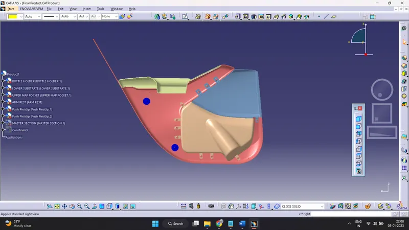
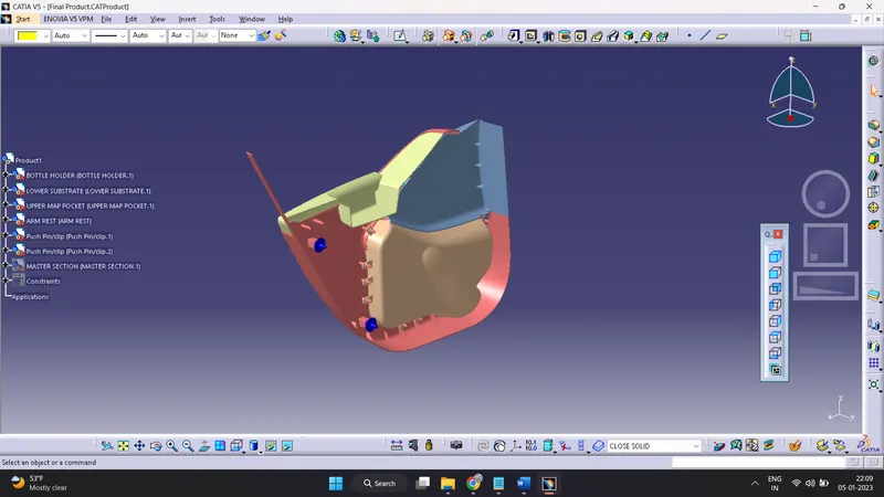
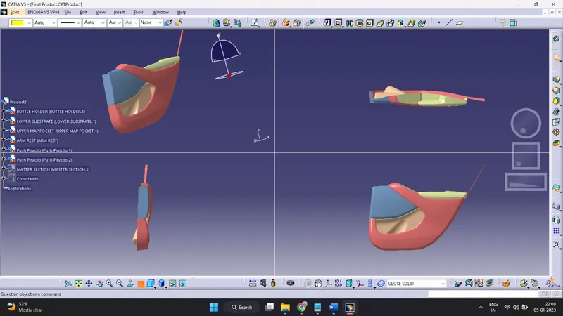
Conclusion:
Creation of the car interior door trim is designed using the given class A surface as the input and Class B and C surface created with the help of Class A surface. By using the given master section attachment features I.e. Heat stakes, Flanges, Dog House and Push Clips are created using the design rules. The draft analysis has been performed to analysis the draft of the component to manufacture easily applying draft to the surface by 3 degree and 0.5 degree to the attachment features. With all data and report we can conclude that draft analysis is very important to design any plastic component to mold the plastic easily. The analysis will verify that all surfaces are favorable for being pulled from a cavity. It may also highlight or given insight to defect areas