Week 11 - Final project
Aim :
To create a door interior part from the inputs of class A surface along with master section by following the design rules By Using CATIA V5.
ObJectives :
- Development of a Door Trim panel
Creation of CAD model considering following inputs as like in OEM and tier1 companies
- a) Class A surface
- b) Nominal thickness : Refer master sections
- c) Attachment strategy :
Find a attachment strategy for the door panel complete work.
Use Push pin with Dog house for Lower substrate – Door panel attachment
Use heat stakes for part to part attachment
- Create thickened part using master section for reference
- Create the mounting features as per design guidelines in the industry and with master sections
- Apply material details :
- Draft analysis & Tooling analysis
- Creation of parting lines and check tooling feasibility
INTRODUCTION:
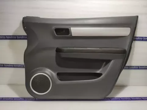
Next to the dashboard, the door trims are the interior parts that contain the most controls and decorative parts. As such, there is a necessity for balancing gap between parts, as well as an overall sense of unity between the numerous parts.
Procedure :
Carefully Observe The Master Section As Shown in fig Given below.
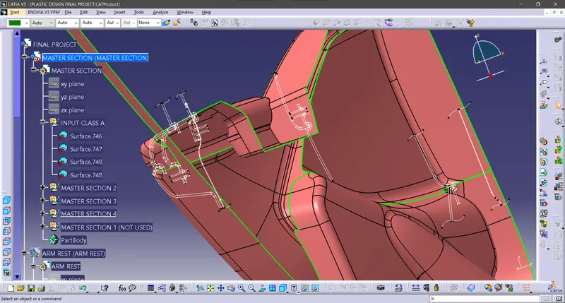
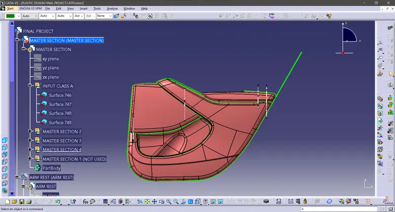
First Thing Is To Load The Mater Section File Into Catia & Then Copy & Clase A Part Surfaces & Paste or Load Them Properly Into The CatProduct.
Then Work On Separately To Create Class A,B,C & Add Engineering Features To Them.
Let We Discuss in Detail Manner in Step By Step :
1.ARM REST
Class A Surface :
We Know that The Class A surfacing is the art in front of the engineering. It is the styling process brought in to digital life.
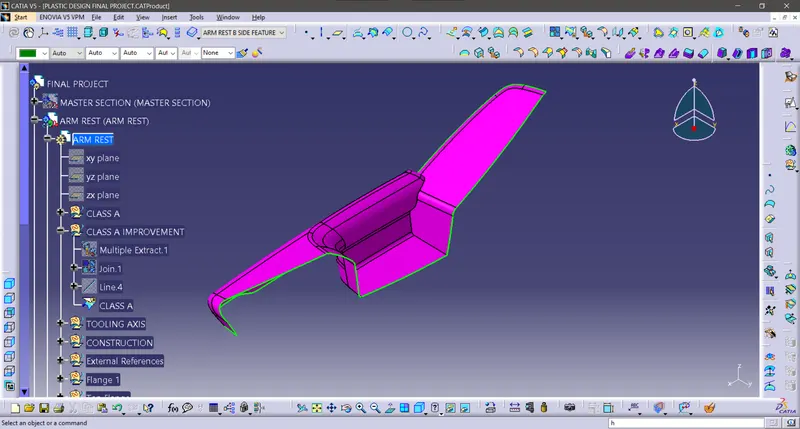
According to the given task we have to thickneed Class A Surface before that we need observe the Class A Surface carefully as shown in figure below.
Tooling Axis :
The tooling axis is a rotated an Angle 1 about the x-axis, then rotated an Angle 2 about the y-axis. Angle 1 about Z, Angle 2 about X. The tool axis is a rotated an Angle 1 about the z-axis, then rotated an Angle 2 about the x-axis.
In Practical based on the removal metal from core & Cavity we need a Centre of the surface that is we called as tooling axis.
Create A line on A Bush or hole or Surface With Respect To point & Plane walls.
(or Else,)
Bisecting Line:
In Geometry, a 'Bisecting line' that divides the line into two different or equal parts. It is applied to the line segments and angles.
Then Create a bisecting line on those 2 lines Which we calles as bisecting line & Hide unwanted surfaces As sown in fgure below.
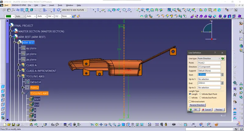
So Lets Begin With The Class B Surface Creation
Insert the Geometrical set respectively,
Class B Surface :
OFFSET OF CLASS A:
By Taking The Offset of Class A Surface to 2.5mm As Shown in Figure Given Below.
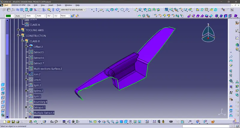
B Surface :
Give Swept,Extract & Extrapolate to the Offset Of A Then we got the B Surface As shown in the figure below.
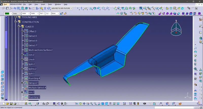
Class C Surface :
The Class C finish allows more imperfections than Class A or B. Class C is often specified for interior surfaces not readily visible, surfaces that will be covered by another part when assembled.
while constructing the C Surface We have to take the Boundaries Of Class A & Swept them & Trim & Join them then we Got the C Surface as shown in figure below.
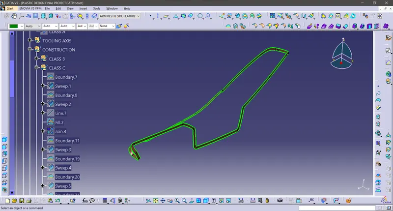
Final Joint :
Join the Class A & B Surfaces & then trim with Class C then we Got the Final component as shown in figure below.
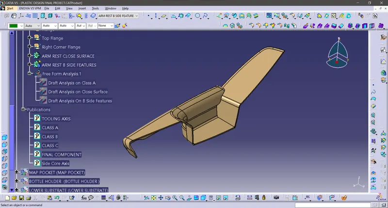
CLOSE SURFACE SOLID BODY :
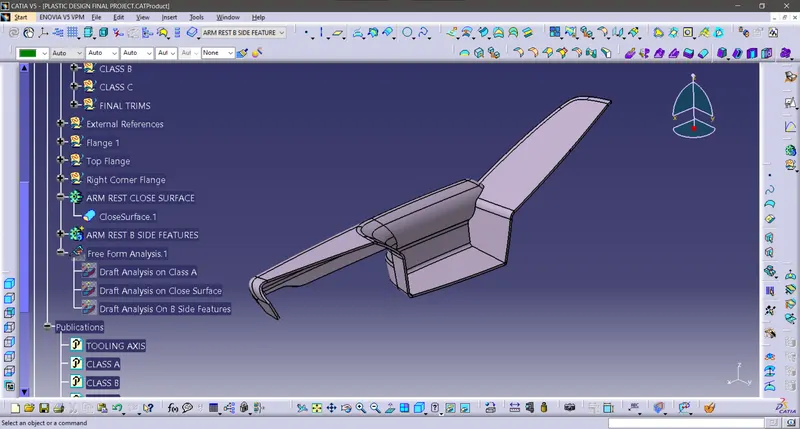
A closed surface contains a volume of space, enclosed from all directions.
Go to the part design workbench & Click the close surface command & click the final trim surface component then the close surface solid body formed as shown in figure below.
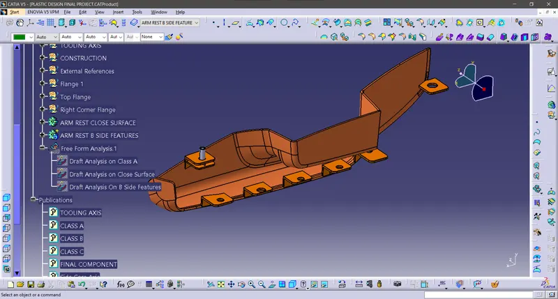
Now Coming To The Creation Of B Side Features :
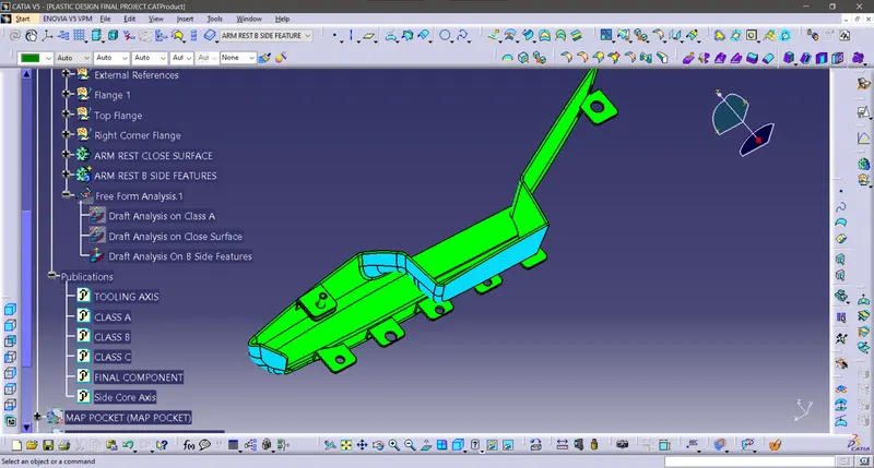
By Following The Design Rules For Heat Stakes & Locators Are with Flange Support As As shown In figure Given Below.
Draft Analysis :
So lets discuss about the draft analysis
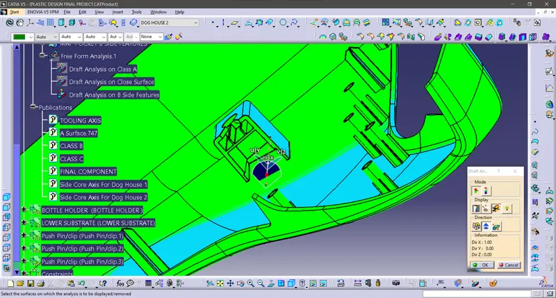
The Draft Analysis allows the user to easily analyze a part for proper draft angle. A Draft Angle describes the amount of taper for molded or cast parts perpendicular to the parting line.
We have 2 modes on the draft analysis Quick & Full analysis respectively.
Under the Display option we have Show are hidden the Color Scale, Analysis under the running point, No Highlight representation & Light effect.
Under the Direction option we have lock or unlock the direction, Compass & Invert.
So According to the practical Usage there Should be 1 to 3degree of angle mostly acceptable, by considering these option we have to test our given & Final Components Draft analysis.
Draft Analysis On Class A surface :
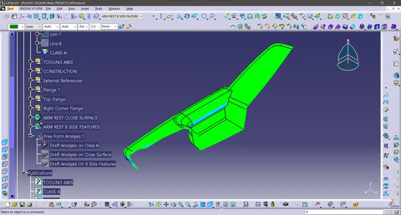
Draft Analysis On Close Surface :
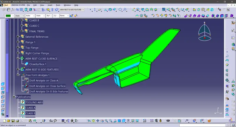
Draft Analysis On Arm engineering Features With Side Core Axis :
2.MAP POCKET
Class A Surface :
We Know that The Class A surfacing is the art in front of the engineering. It is the styling process brought in to digital life.
According to the given task we have to thickneed Class A Surface before that we need observe the Class A Surface carefully as shown in figure below.
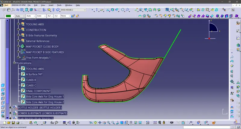
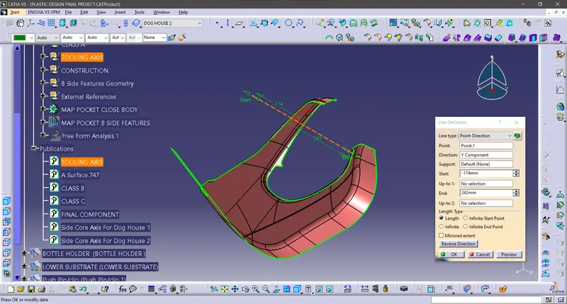
Tooling Axis :
The tooling axis is a rotated an Angle 1 about the x-axis, then rotated an Angle 2 about the y-axis. Angle 1 about Z, Angle 2 about X. The tool axis is a rotated an Angle 1 about the z-axis, then rotated an Angle 2 about the x-axis.
In Practical based on the removal metal from core & Cavity we need a Centre of the surface that is we called as tooling axis.
As sown in fgure below.
So Lets Begin With The Class B Surface Creation
Insert the Geometrical set respectively,
Class B Surface :
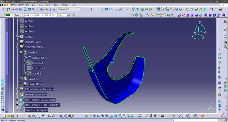
OFFSET OF CLASS A:
By Taking The Offset of Class A Surface to 2.5mm As Shown in Figure Given Below.
B Surface :
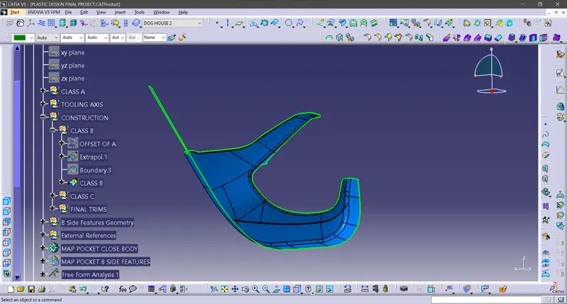
Give Swept,Extract & Extrapolate to the Offset Of A Then we got the B Surface As shown in the figure below.
Class C Surface :
The Class C finish allows more imperfections than Class A or B. Class C is often specified for interior surfaces not readily visible, surfaces that will be covered by another part when assembled.
while constructing the C Surface We have to take the Boundaries Of Class A & Swept them & Trim & Join them then we Got the C Surface as shown in figure below.
Final Joint :
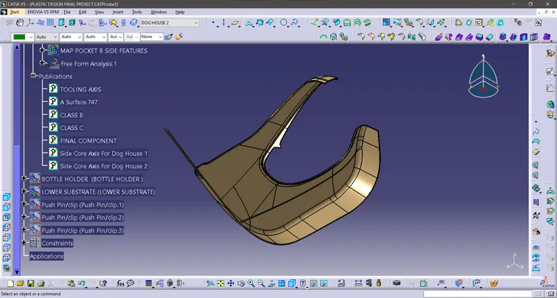
Join the Class A & B Surfaces & then trim with Class C then we Got the Final component as shown in figure below.
CLOSE SURFACE SOLID BODY :
A closed surface contains a volume of space, enclosed from all directions.
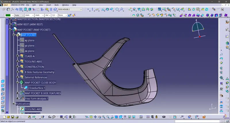
Go to the part design workbench & Click the close surface command & click the final trim surface component then the close surface solid body formed as shown in figure below.
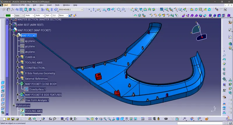
Now Coming To The Creation Of B Side Features :
By Following The Design Rules For Heat Stakes & Locators Are with Flange Support As As shown In figure Given Below.
Draft Analysis :
So lets discuss about the draft analysis
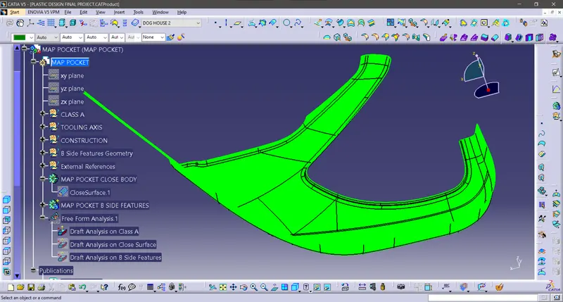
The Draft Analysis allows the user to easily analyze a part for proper draft angle. A Draft Angle describes the amount of taper for molded or cast parts perpendicular to the parting line.
We have 2 modes on the draft analysis Quick & Full analysis respectively.
Under the Display option we have Show are hidden the Color Scale, Analysis under the running point, No Highlight representation & Light effect.
Under the Direction option we have lock or unlock the direction, Compass & Invert.
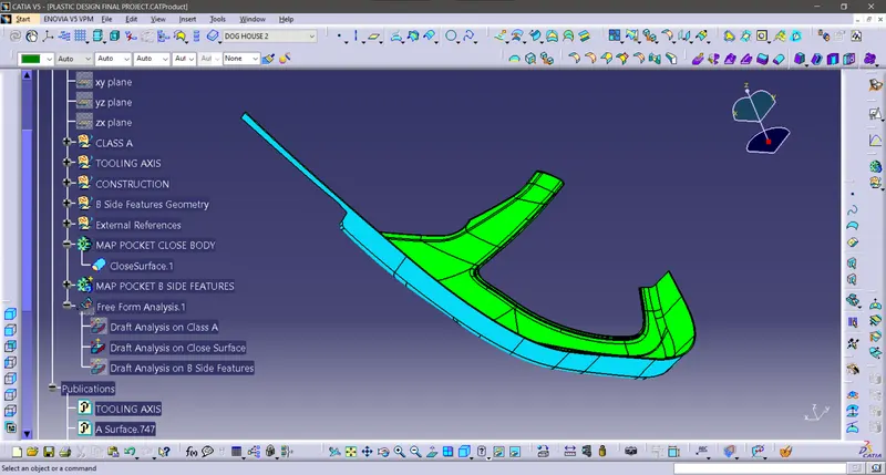
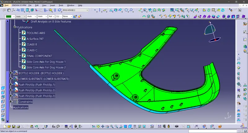
So According to the practical Usage there Should be 1 to 3degree of angle mostly acceptable, by considering these option we have to test our given & Final Components Draft analysis.
Draft Analysis On Class A surface :
Draft Analysis On CLOSE BODY :
Draft Analysis On ENGINEERING FEATURES :
3.BOTTLE HOLDER
Class A Surface :
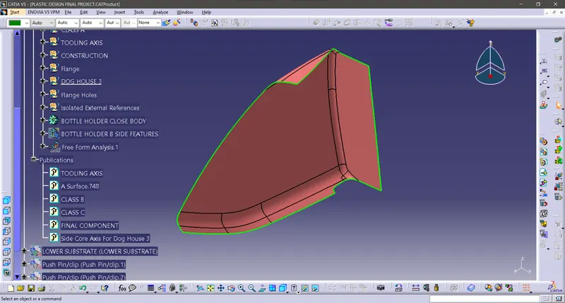
We Know that The Class A surfacing is the art in front of the engineering. It is the styling process brought in to digital life.
According to the given task we have to thickneed Class A Surface before that we need observe the Class A Surface carefully as shown in figure below.
Tooling Axis :
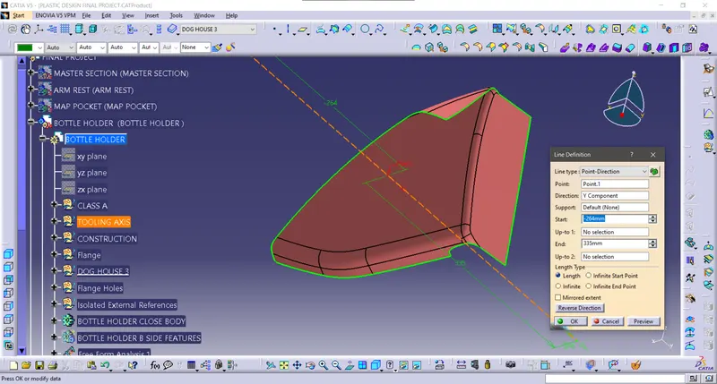
The tooling axis is a rotated an Angle 1 about the x-axis, then rotated an Angle 2 about the y-axis. Angle 1 about Z, Angle 2 about X. The tool axis is a rotated an Angle 1 about the z-axis, then rotated an Angle 2 about the x-axis.
In Practical based on the removal metal from core & Cavity we need a Centre of the surface that is we called as tooling axis.
Create A Dummy lines on A Bush or hole walls & Then Intersect them.
So Lets Begin With The Class B Surface Creation
Insert the Geometrical set respectively,
Class B Surface :
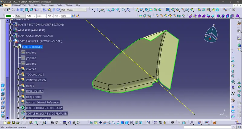
OFFSET OF CLASS A:
By Taking The Offset of Class A Surface to 2.5mm As Shown in Figure Given Below.
B Surface :
Give Swept,Extract & Extrapolate to the Offset Of A Then we got the B Surface As shown in the figure below.
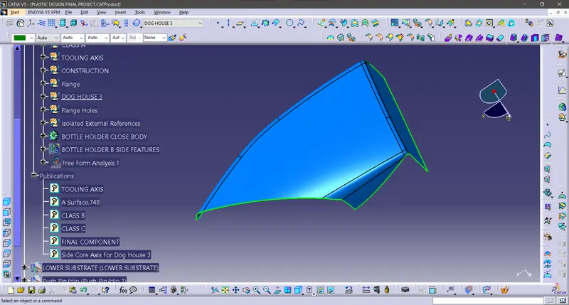
Class C Surface :
The Class C finish allows more imperfections than Class A or B. Class C is often specified for interior surfaces not readily visible, surfaces that will be covered by another part when assembled.
while constructing the C Surface We have to take the Boundaries Of Class A & Swept them & Trim & Join them then we Got the C Surface as shown in figure below.
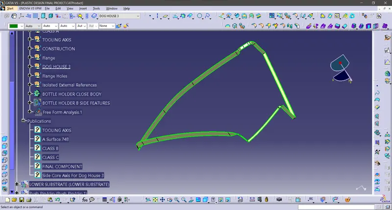
Final Joint :
Join the Class A & B Surfaces & then trim with Class C then we Got the Final component as shown in figure below.
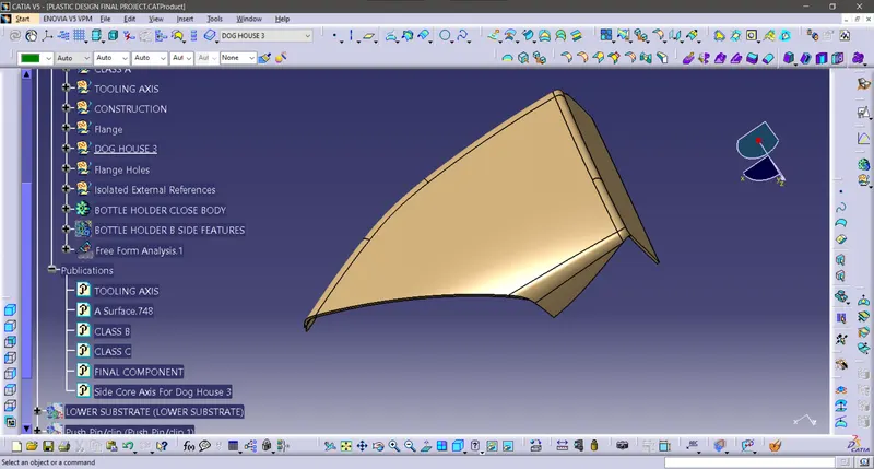
CLOSE SURFACE SOLID BODY :
A closed surface contains a volume of space, enclosed from all directions.
Go to the part design workbench & Click the close surface command & click the final trim surface component then the close surface solid body formed as shown in figure below.
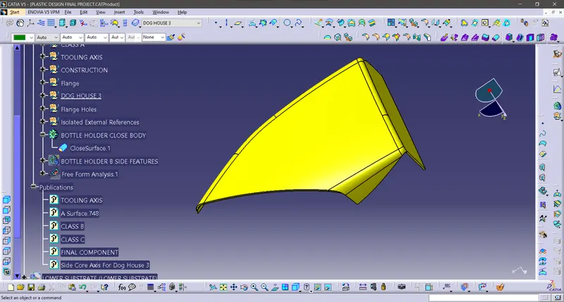
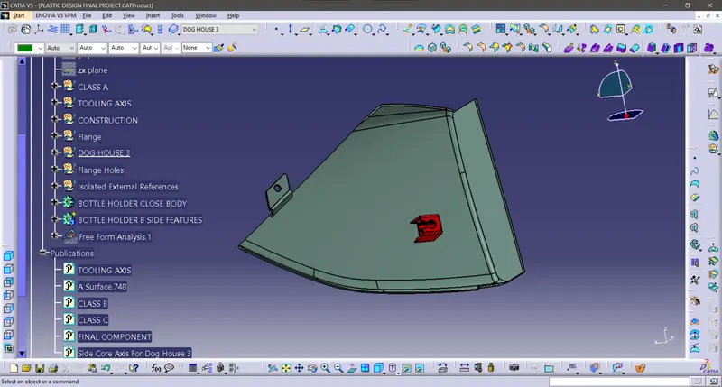
Now Coming To The Creation Of ENGINEERING FEATURES :
By Following The Design Rules For Heat Stakes & Locators Are with Flange Support As As shown In figure Given Below.
Draft Analysis :
So lets discuss about the draft analysis
The Draft Analysis allows the user to easily analyze a part for proper draft angle. A Draft Angle describes the amount of taper for molded or cast parts perpendicular to the parting line.
We have 2 modes on the draft analysis Quick & Full analysis respectively.
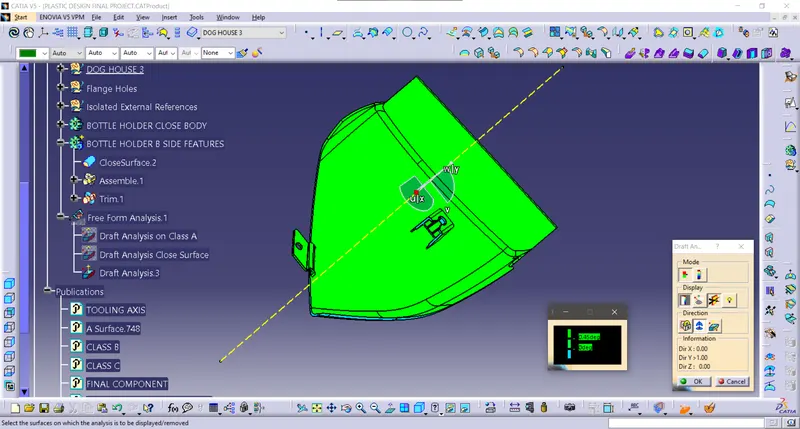
Under the Display option we have Show are hidden the Color Scale, Analysis under the running point, No Highlight representation & Light effect.
Under the Direction option we have lock or unlock the direction, Compass & Invert.
So According to the practical Usage there Should be 1 to 3degree of angle mostly acceptable, by considering these option we have to test our given & Final Components Draft analysis.
Draft Analysis On Class A surface :
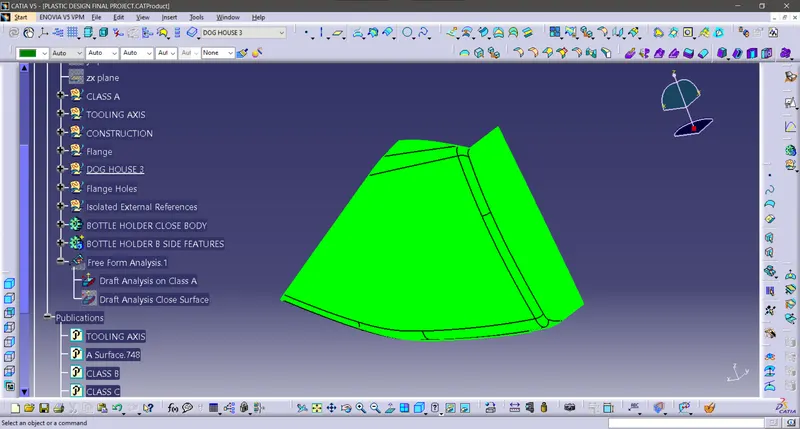
Draft Analysis On ClOSE BODY surface :
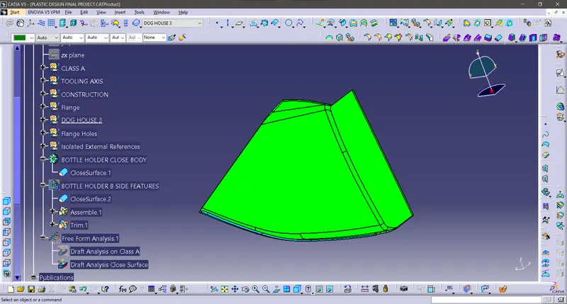
Draft Analysis On ClOSE BODY ENGINEERING FEATURES :
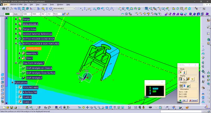
4. LOWER SUBSTRATE :
Let We Discuss in Detail Manner in Step By Step :
Class A Surface :
We Know that The Class A surfacing is the art in front of the engineering. It is the styling process brought in to digital life.
According to the given task we have to thickneed Class A Surface before that we need observe the Class A Surface carefully as shown in figure below.
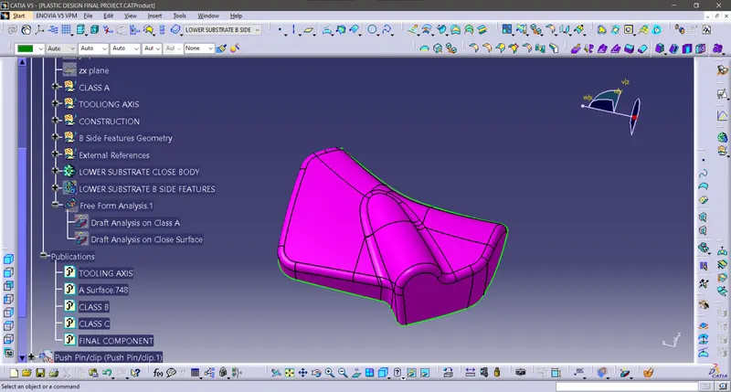
Tooling Axis :
The tooling axis is a rotated an Angle 1 about the x-axis, then rotated an Angle 2 about the y-axis. Angle 1 about Z, Angle 2 about X. The tool axis is a rotated an Angle 1 about the z-axis, then rotated an Angle 2 about the x-axis.
In Practical based on the removal metal from core & Cavity we need a Centre of the surface that is we called as tooling axis.
As sown in fgure below.
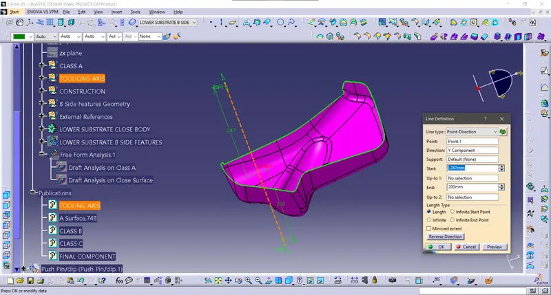
So Lets Begin With The Class B Surface Creation
Insert the Geometrical set respectively,
Class B Surface :
By Taking The Offset of Class A Surface to 2.5mm As Shown in Figure Given Below.
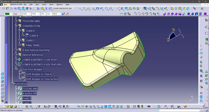
Class C Surface :
The Class C finish allows more imperfections than Class A or B. Class C is often specified for interior surfaces not readily visible, surfaces that will be covered by another part when assembled.
while constructing the C Surface We have to take the Boundaries Of Class A & Swept them & Trim & Join them then we Got the C Surface as shown in figure below.
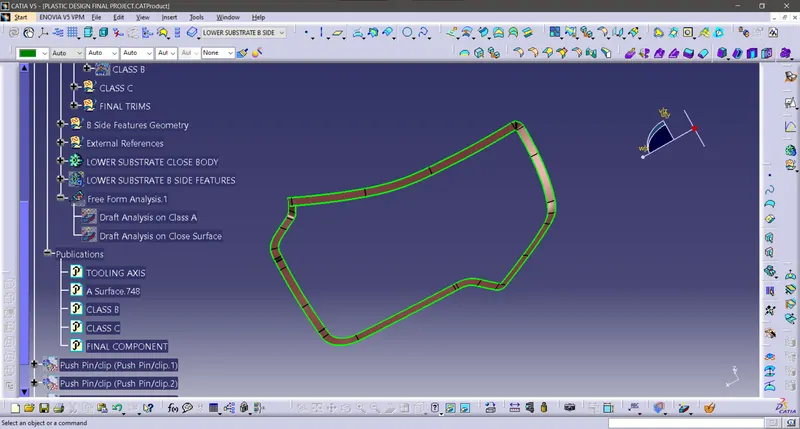
Final Joint :
Join the Class A & B Surfaces & then trim with Class C then we Got the Final component as shown in figure below.
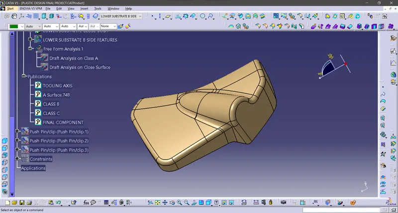
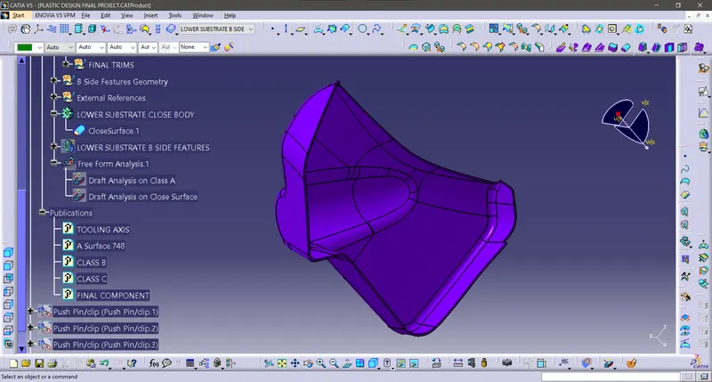
CLOSE SURFACE SOLID BODY :
A closed surface contains a volume of space, enclosed from all directions.
Go to the part design workbench & Click the close surface command & click the final trim surface component then the close surface solid body formed as shown in figure below.
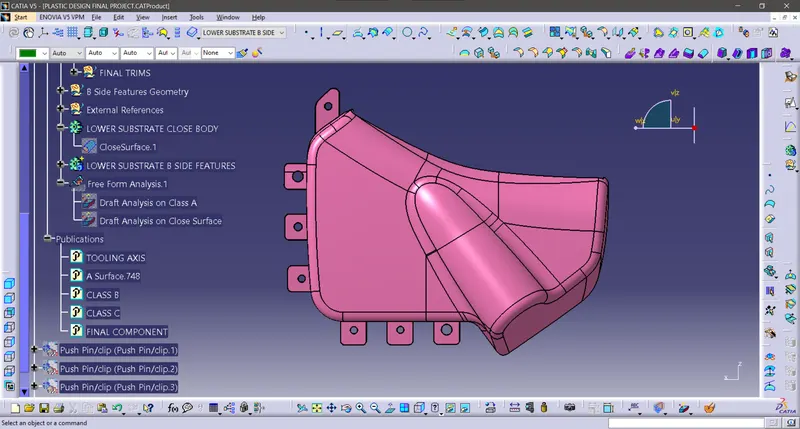
Now Coming To The Creation Of ENGINEERING FEATURES :
By Following The Design Rules For Heat Stakes & Locators Are with Flange Support As As shown In figure Given Below.
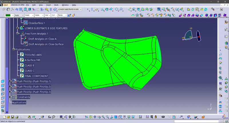
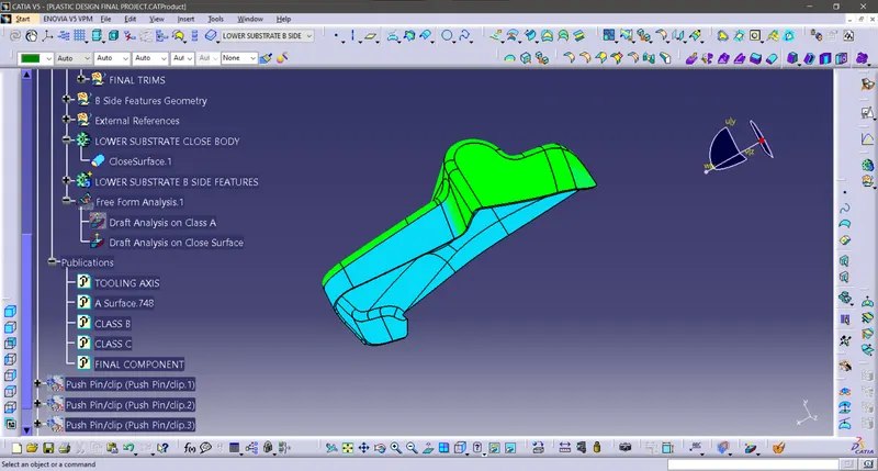
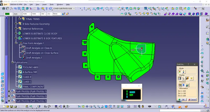
Draft Analysis :
So lets discuss about the draft analysis
The Draft Analysis allows the user to easily analyze a part for proper draft angle. A Draft Angle describes the amount of taper for molded or cast parts perpendicular to the parting line.
We have 2 modes on the draft analysis Quick & Full analysis respectively.
Under the Display option we have Show are hidden the Color Scale, Analysis under the running point, No Highlight representation & Light effect.
Under the Direction option we have lock or unlock the direction, Compass & Invert.
So According to the practical Usage there Should be 1 to 3degree of angle mostly acceptable, by considering these option we have to test our given & Final Components Draft analysis.
Draft Analysis On Class A surface :
Draft Analysis On CLOSE surface :
Draft Analysis On ENGINEERINF FEATURES :
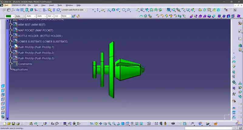
5. PUSH PIN :
It was Helps To Hold or strengthen the engineering features as shown in Figure given below.
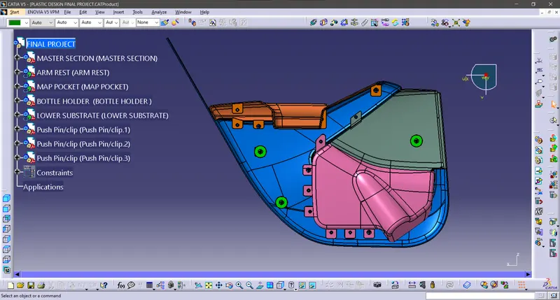
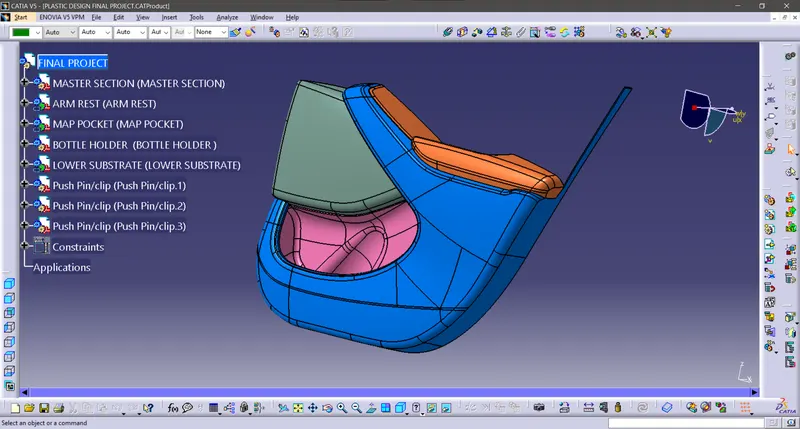
Final Assembly :
Fix All Parts & Constrain the Push Clips As As shown in figure given below :
CONCLUSION
Thus the door interior part has been created Sucessfully from the inputs of class A surface along with master section by following the design rules followed in tier 1 and OEM industries in catia v5.