Week 11 - Final project
FINAL PROJECT -
DOOR TRIM DEVELOPMENT -
INPUTS:
- CLASS A surfaces of the DOOR ARM REST, MAP POCKET, BOTTLE HOLDER and LOWER SUBSTRATE.
- Master section for the attachment features.
- Push clips for the assembly.
OBJECTIVES:
- Analysing the class A and performing necessary modification to obtain the modified class A.
- Creating the tooling axis for all the components .
- Performing draft analysis of class A surface.
- Creating the class B surface with the help of surface workbench.
- Creating the class C surface with necessary draft.
- Trimmimg the CLASS A,B AND C Surface for obtaining the final trim for all the components.
- Creating the closed body for all the components.
- Creating the attachments on the LOWER SUBSTRATE for assembly like DOG HOUSE, HEAT STAKES, AND RIBS.
- Creating the flanges on the other three components for the assembly purpose.
- Creating the Side core tolling axis.
- Performing the vigrous draft analysis and make sure all parts are clearing with positive and required draft.
- Assembly of the push pins over the dog house in assembly workbench.
- Final submission.
ANALYSING THE PROJECT:
- DOOR TRIM DEVELOPMENT IN CATIA V5.
About the software: CATIA V5
CATIA is the world’s engineering and design leading software for product 3D CAD design excellence.It is used to design, simulate, analyze, and manufacture products in a variety of industries including aerospace, automotive, consumer goods, and industrial machinery, just to name a few. It addresses all manufacturing organizations, from OEMs through their supply chains, to small independent producers.
If you stop and take a look around, CATIA is everywhere. CATIA is in the plane that just flew over, the car that just went silently by, the phone you just answered, and the bottle of water that you just finished.
Here, we have used the PART , SHAPE(GENERATIVE SHAPE DESIGN ) AND PRODUCT/ ASSEMBLY WORKBENCH.
The door panel is divided into four parts for -
- Door Arm Rest.
- Lower substrate.
- Upper Map Pocket.
- Lower Map Pocket.
1. DOOR ARM REST CREATION -
INTRODUCTION:
CLASS-A SURFACE: A surface made by the designer which is given as input to the plastic modeler to work on. It is an aesthetic surface
and the outermost surface.
CLASS-B SURFACE: A surface below a certain thickness from the class-A surface is a class-B surface. This is the surface that contains
engineering aspects of a model.
CLASS-C SURFACE: A surface that joins class-A and class-B surfaces is a class-C surface.
Methodology :
In this design we will focus on the following steps
- Tooling Axis
- Draft Analysis
- Class B Surface
- Class C Surface
- Making a solid model from Class A surface
Following tools were used to reach the final Solid Model :
- Extract
- Un - trim
- Trim
- Offset
- Extrapolate
- Boundary
- Edge Fillet
- Sweep
- Join
- Close Surface ( Part Design )
Class A Given -
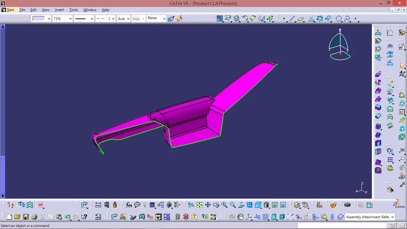
Design Check (Pre Check) on received Class A :-
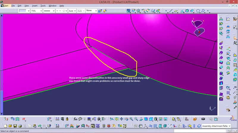
- After receiving the Class-A for the connectivity of the surfaces on it.
- Use boundary operation and disassemble.
- 2 discontinuities was found small gap and a sharp edge as shown in the figure below.
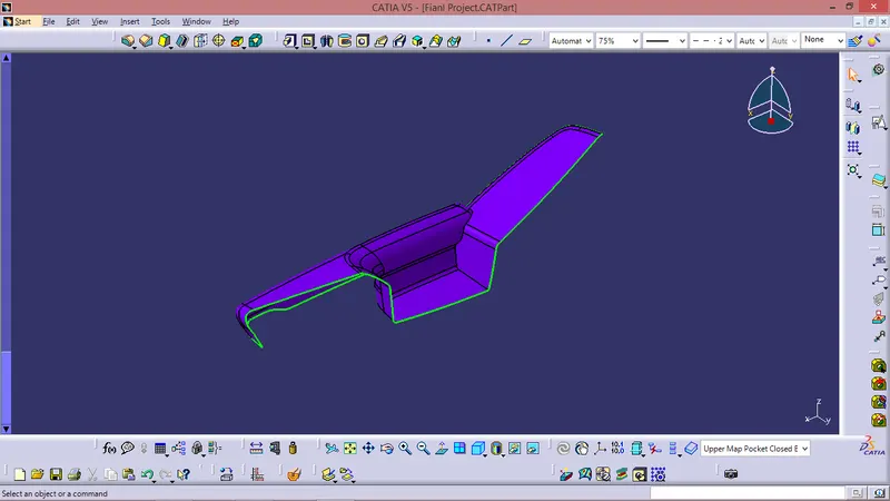
Corrected Class A Surface -
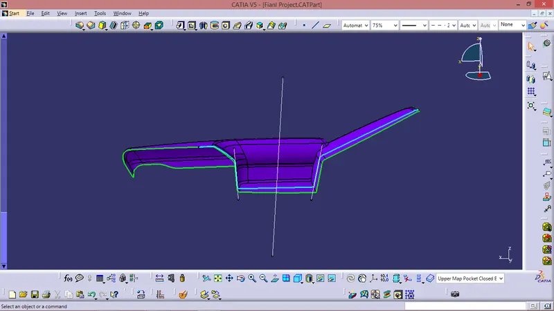
Tooling Axis Creation -
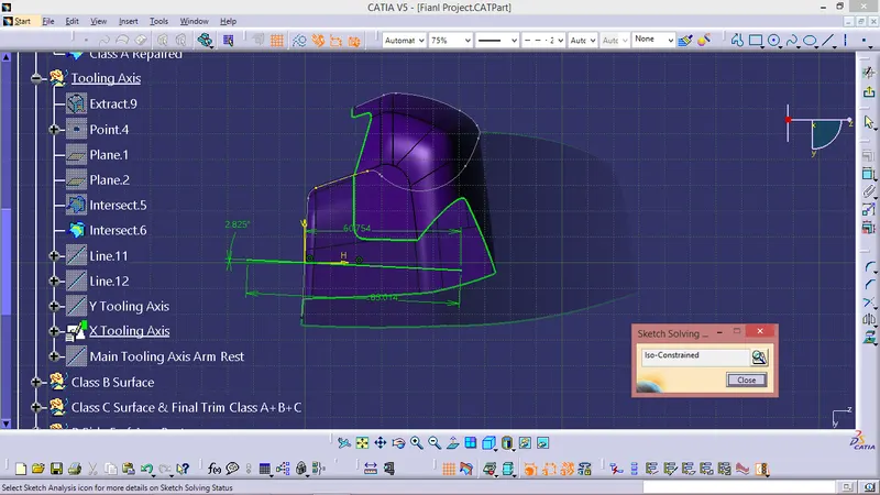
Tooling direction is main consideration for plastic part and mold parts because it defines movement of mold part and possibility of plastic part to come-out from mold part (Core and Cavity).
- In Molding machine arrangement is given to open the mold along a direction which is known as Tooling Direction.
- In other words. The mold is built from two separate halves (Core and Cavity) and tooling direction basically define the direction of mold pulls apart.
- Tooling direction is known as primary direction.
There are two methods to create Tooling Axis -
- Bisecting method &
- Inertia method
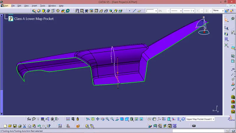
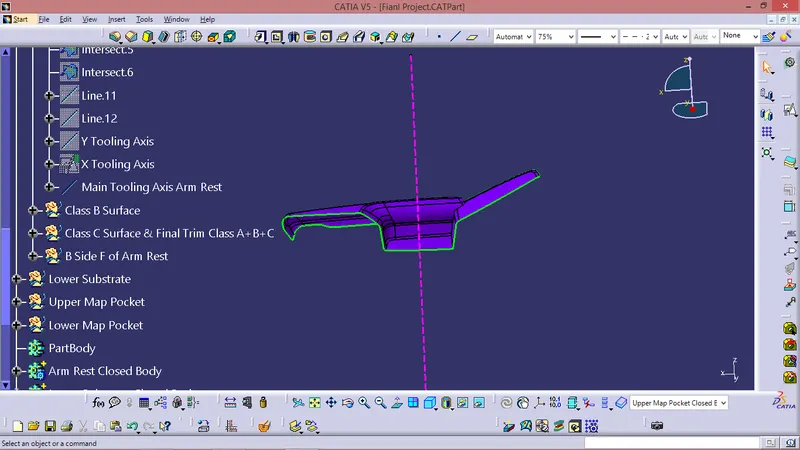
For this Component Tooling Axis is created by Bisecting method -
- By taking Extract of the base and creating a point on centre of the extact and then creating axis system or plane on that point .
- Intersecting the Class A with the point .
- Creating bisecting line using the extracts on the intersection .
- Checking the tooling axis created is clearing all the sides of the Class A by keeping it in Normal view mode.
FOR CLASS B SURFACE :
- Invisible Surfaces.
- Surface mostly don't have textures
- Surface needs to be created according to the class-A surface.
- Having all features in B-side surface only.
- Surfaces which is having TANGENT CONTINUITY IS CALLED class-B
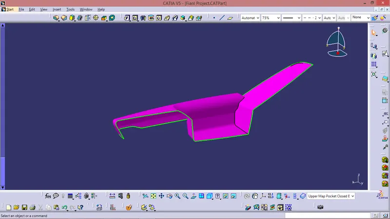
Just Offseted the Class A as per the Master Section given & performed some modifications as per requirement.
FOR CLASS C SURFACE:
Took boundries for class A in some sections and in other sections took Multiple extract for Class A Surface.
Sweept using boundries and Multiple Extract with Reference surface.
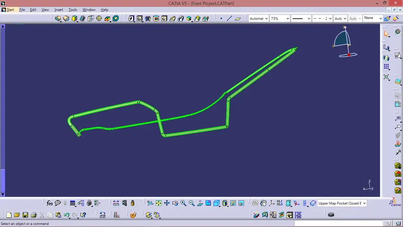
CLASS A CLASS C TRIM
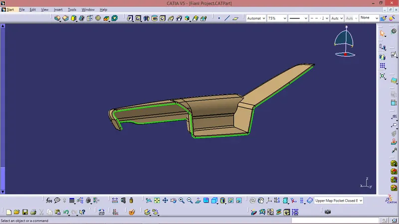
Final Trim -
Class A + Class B + Class C
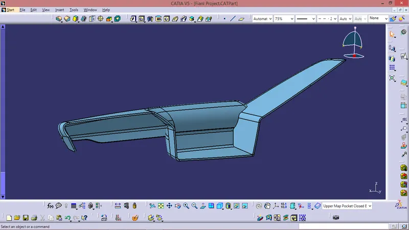
Closed Body -
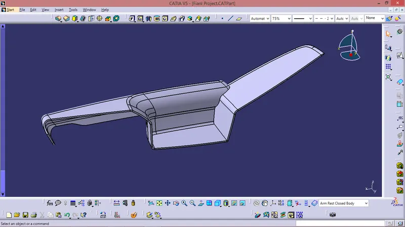
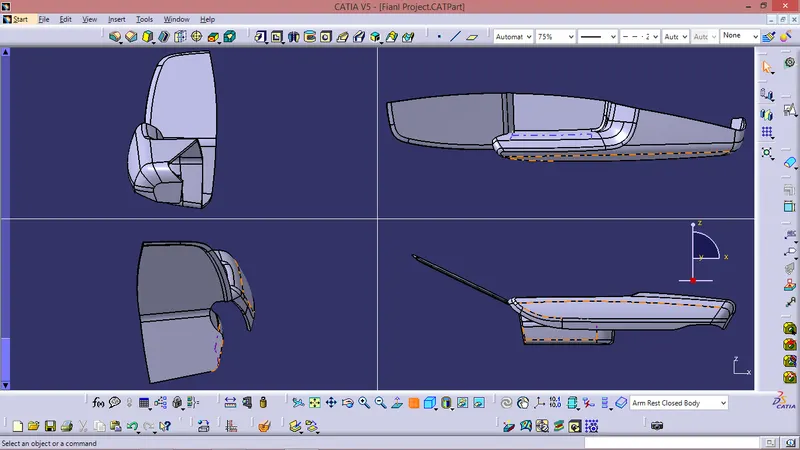
B SIDE FEATURES -
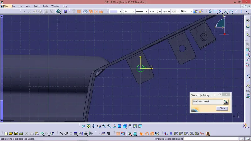
Sketches -
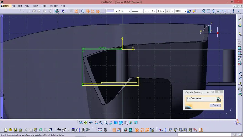
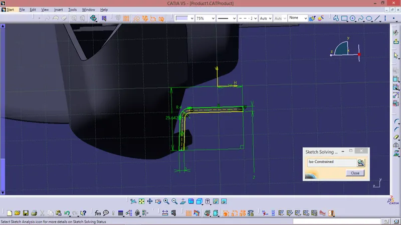
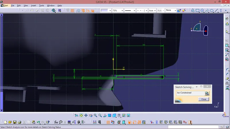
Components-
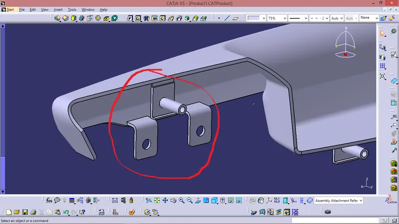
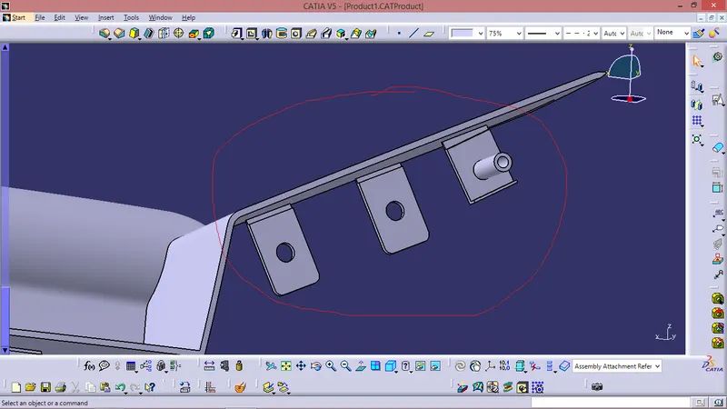
DRAFT ANALYSIS :
Class A surface draft analysis -
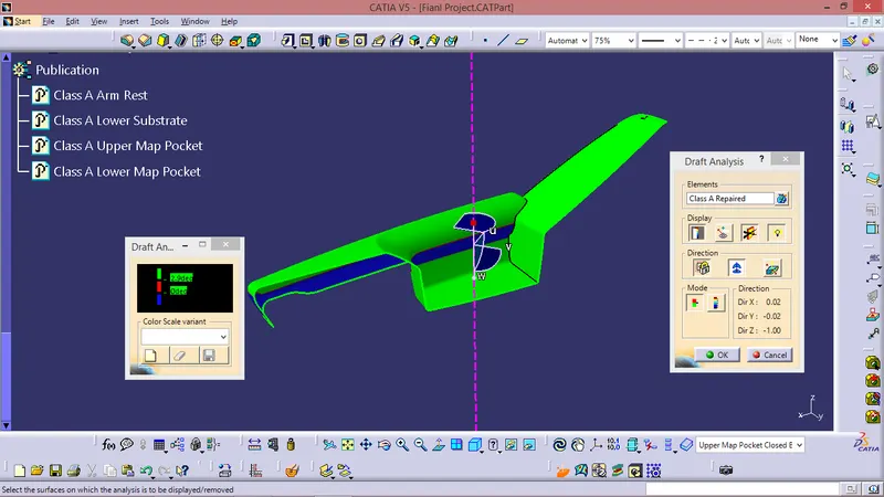
The above image shows the draft analysis in which green color surfaces shows that they are having an angle of more than 3 degrees but the surface in red color shows it is less than 3 degree. These are the results of the draft analysis which are very crucial for determining the feasibility of the product
Solid component draft analysis :
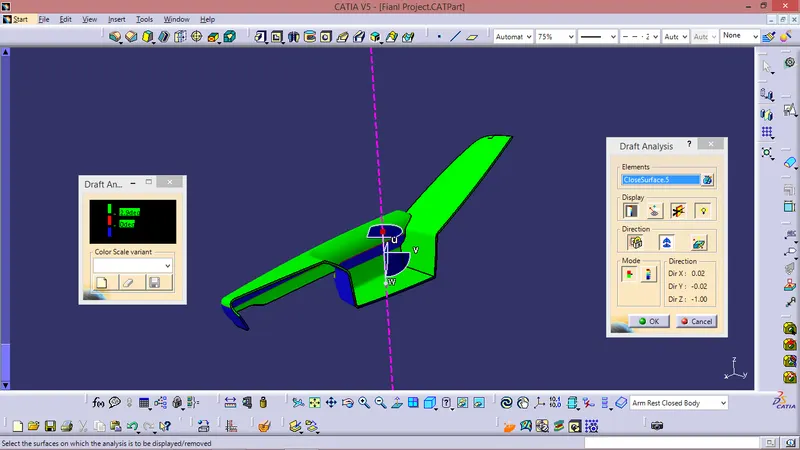
The draft analysis command enables you to detect if the part you drafted will be easily removed. This type of analysis is performed based on colour range identifying zones on the analysed element where the deviation from the draft direction at any point, corresponds to specified values. After draft analysis done we can observe that the green colour shows that the drafted walls of the switch bezel are above 3 degrees which is a permissible criteria to manufacture in injection moulding.
NOTE - Some tiny patches on the Class A surface was 0 deg draft same has been reflected on the Closed Body .
Draft Analysis. For Final Closed Body With Attachment Features -
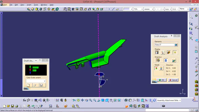
- Draft analysis is done on the final part with the tooling axis as reference
- Green surface indicates the areas where the draft is more than 0.5 degrees.
- Blue surface indicates the area having negative draft.
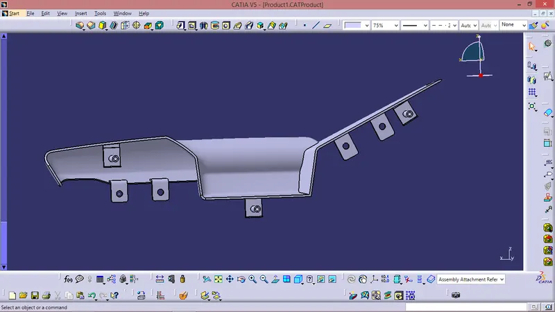
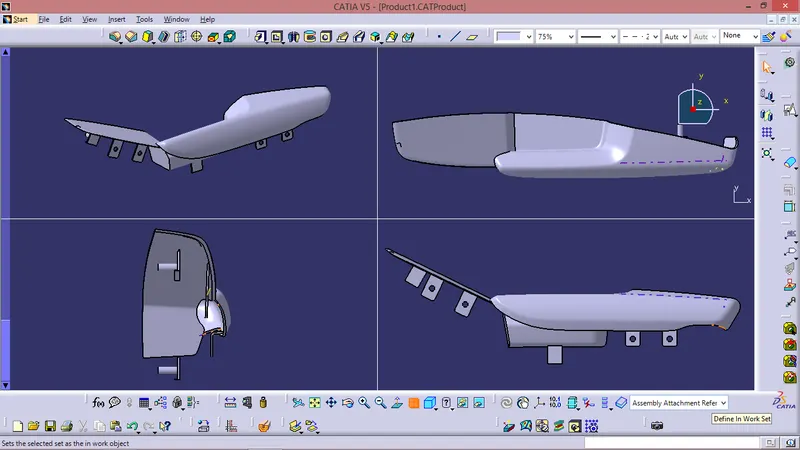
Closed Body With Attachment Features -
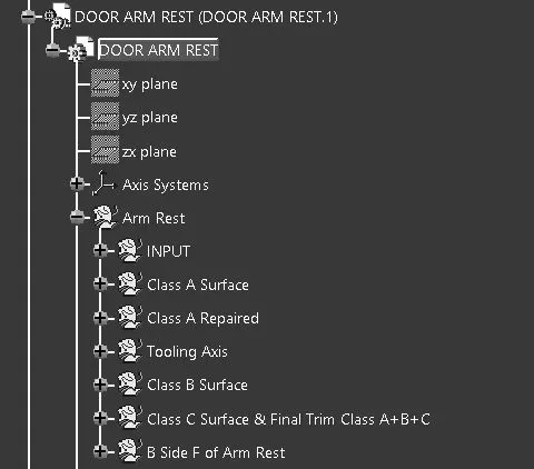
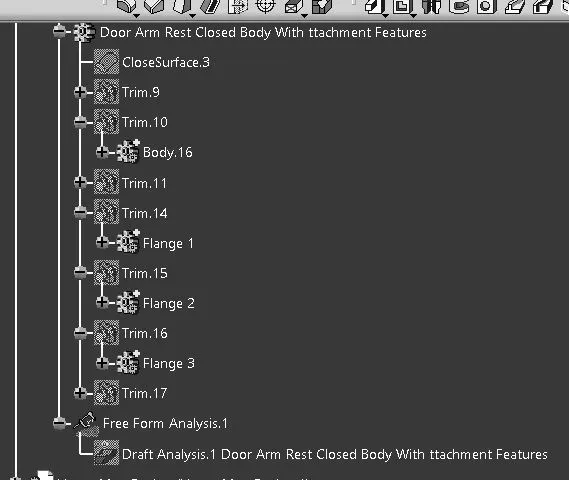
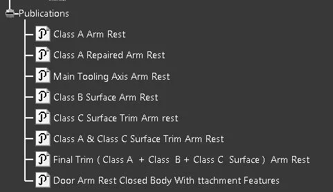
TREE STRUCTURE :
LOWER SUBSTARTE CREATION
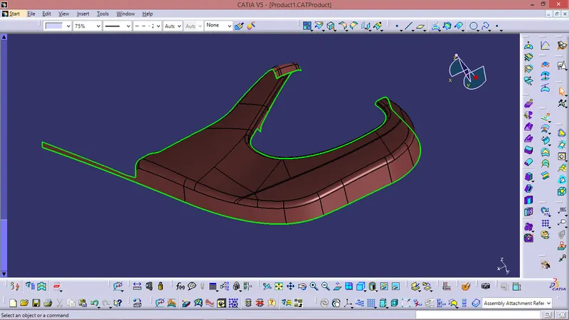
Class A Given -
Tooling Axis Creation -
Tooling direction is main consideration for plastic part and mold parts because it defines movement of mold part and possibility of plastic part to come-out from mold part (Core and Cavity).
- In Molding machine arrangement is given to open the mold along a direction which is known as Tooling Direction.
- In other words. The mold is built from two separate halves (Core and Cavity) and tooling direction basically define the direction of mold pulls apart.
- Tooling direction is known as primary direction.
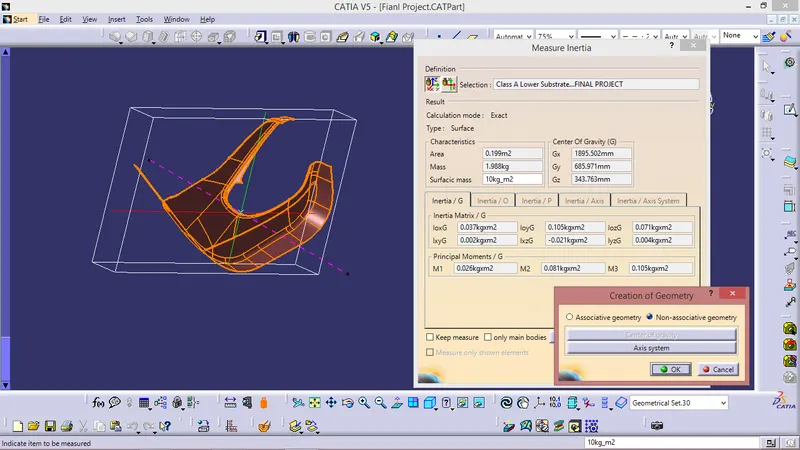
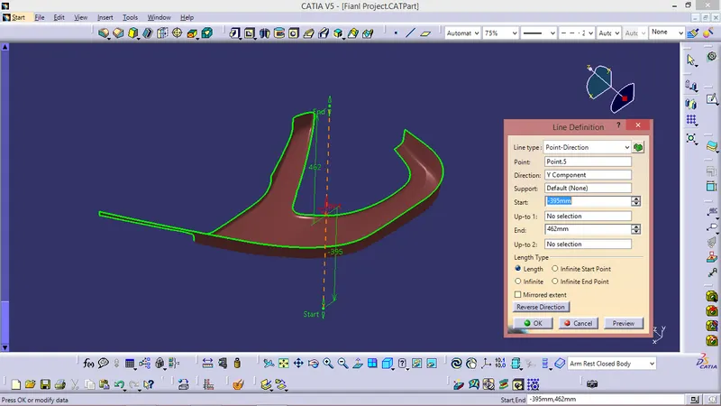
In this given Lower Substrate Class A surface the tooling axis is created using inertia method as shown in the fig below -
FOR CLASS B SURFACE :
- Invisible Surfaces.
- Surface mostly don't have textures
- Surface needs to be created according to the class-A surface.
- Having all features in B-side surface only.
- Surfaces which is having TANGENT CONTINUITY IS CALLED class-B
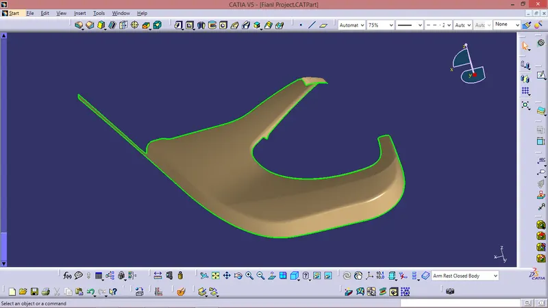
Just Offseted the Class A as permaster section & performed some modifications as per requirement.
FOR CLASS C SURFACE:
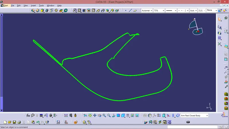
Took boundries for class A in some sections and in other sections took Multiple extract for Class A Surface.
Sweept using boundries and Multiple Extract with Reference surface.
CLASS A CLASS C TRIM
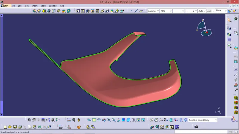
Final Trim -
Class A + Class B + Class C
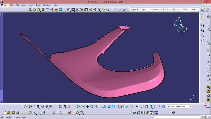
B SIDE FEATURES -
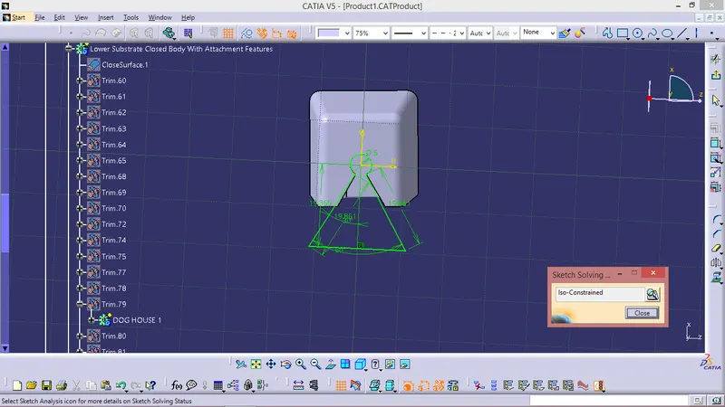
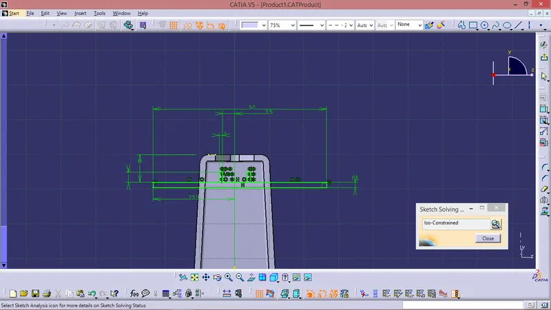
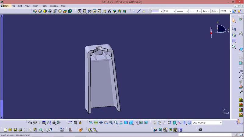
For Creating Dog house -
- Design Rules for Dog house
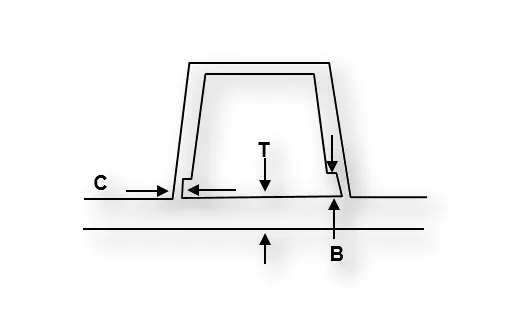
- "C" is where the doghouse contacts the backside of the surface
-
Doghouse wall thickness at the intersection of the part wall ( C ) should be 40% or less than the main wall stock ( T ).
- The height of ( B ) should be between 3.0 – 6.0 mm
Sketch-
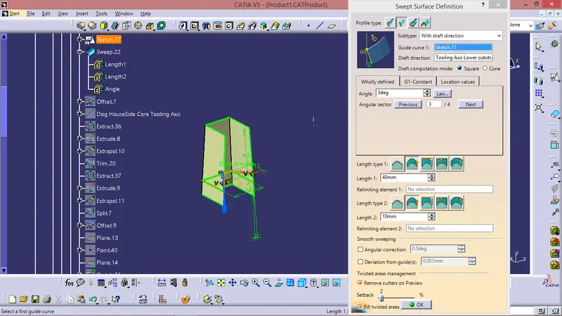
Inside Ribs And Hole upside -
Dog House -
LOCATORS & HEAT STAKES
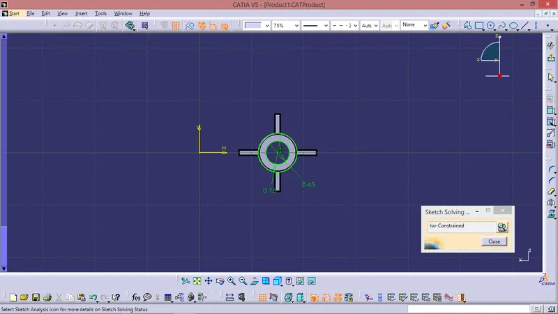
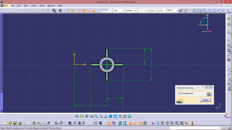
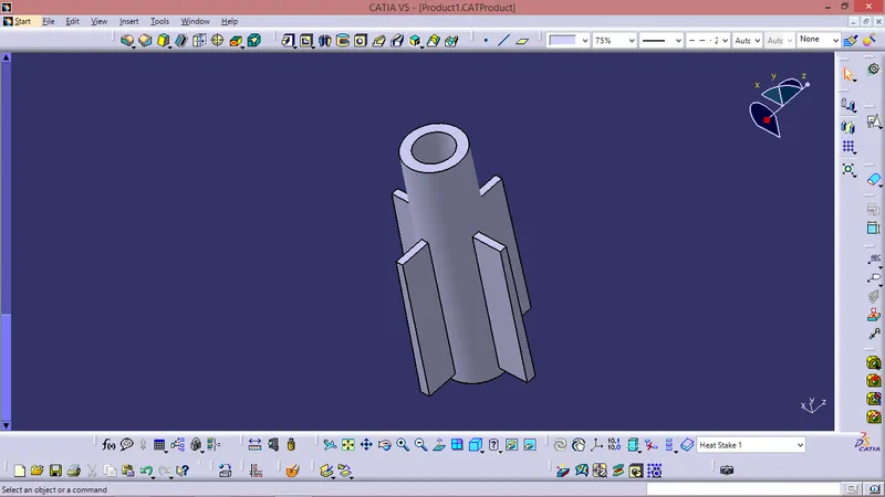
DESIGN OF HEAT STAKES WITH RIBS :
Take gemoetrical set and drawn a sketch with reference of plane and projection point apply PAD for the sketch with in the dimension limits by NEUTRAL FIBER.
DRAFT Value = 0.5
Apply Fillets where required - 0.3 mm or 0.5 mm .
There are 16 Heat stakes on 13 different points in the model as shown in the figure in question
Sketch -
Component-
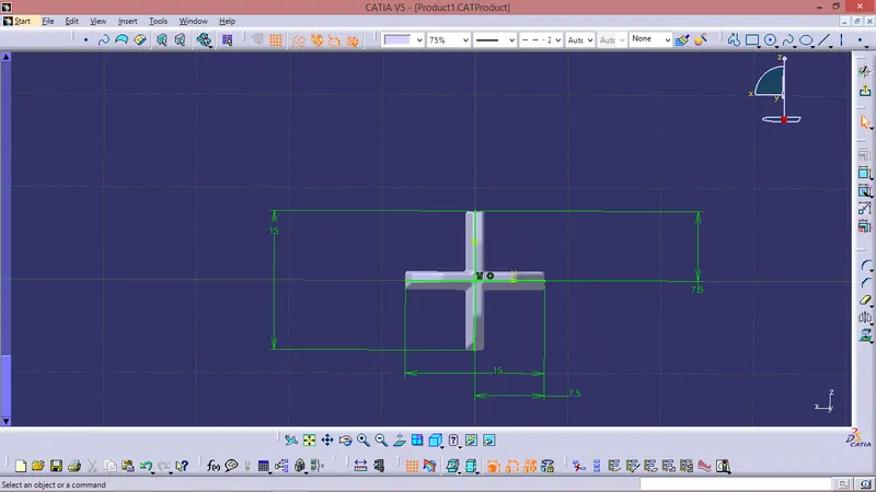
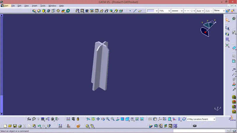
DESIGN OF 4 WAY LOCATORS :
Take gemoetrical set and draw sketch with reference of plane and projection point & then give PAD for the sketch with in the dimension limits selecting NEUTRAL FIBER .
Thickness = 1.3
Draft Value = 0.5
Apply Fillets where required - 0.3 mm or 0.5 mm
There are two 4 WAY LOCATOR on the model as shown in the figure in question .
Sketch-
Componenet -
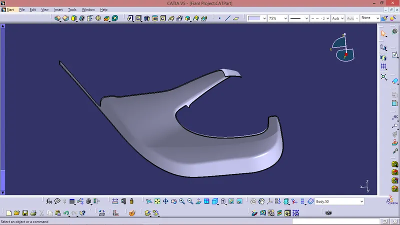
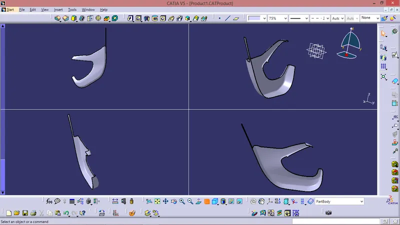
Closed Body -
DRAFT ANALYSIS :
Class A surface draft analysis -
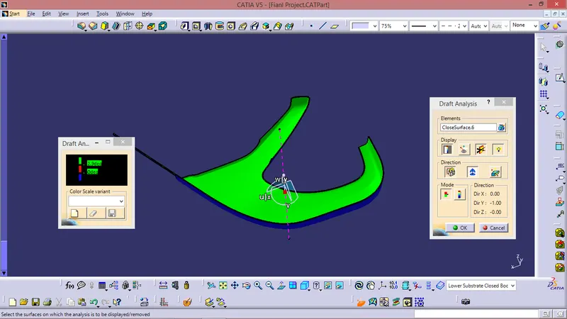
The above image shows the draft analysis in which green color surfaces shows that they are having an angle of more than 3 degrees but the surface in red color shows it is less than 3 degree. These are the results of the draft analysis which are very crucial for determining the feasibility of the product
Solid component draft analysis :

The draft analysis command enables you to detect if the part you drafted will be easily removed. This type of analysis is performed based on colour range identifying zones on the analysed element where the deviation from the draft direction at any point, corresponds to specified values. After draft analysis done we can observe that the green colour shows that the drafted walls of the switch bezel are above 3 degrees which is a permissible criteria to manufacture in injection moulding.
Draft Analysis For Dog House -
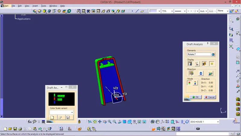
Draft Analysis. For Final Closed Body With Attachment Features -
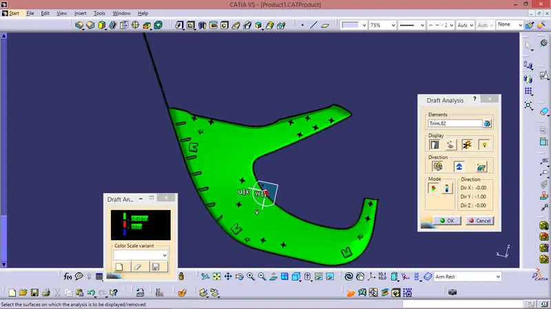
- Draft analysis is done on the final part with the tooling axis as reference
- Green surface indicates the areas where the draft is more than 0.5 degrees.
- Blue surface indicates the area having negative draft.
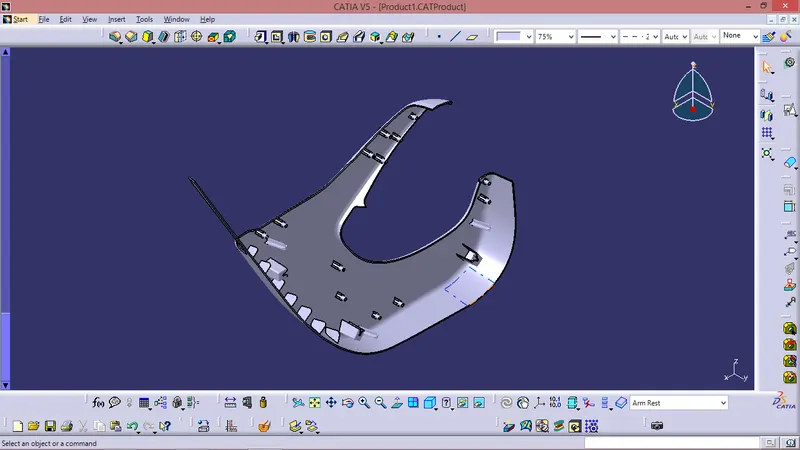
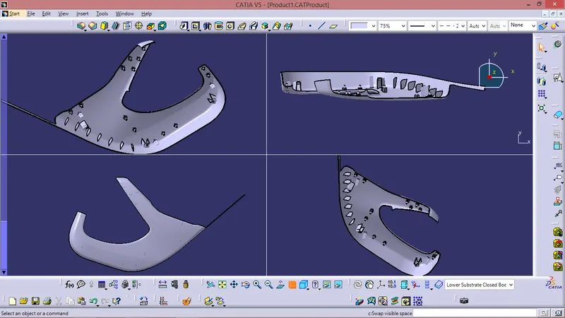
Closed Body With Attachment Features -
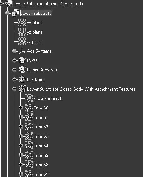
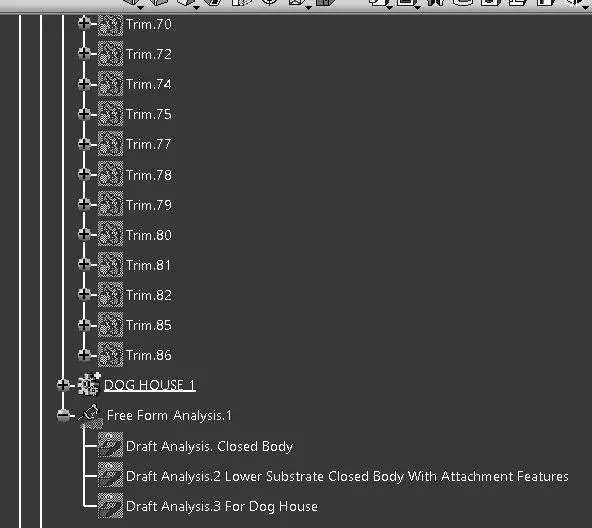
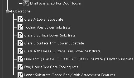
TREE STRUCTURE :
UPPER MAP POCKET
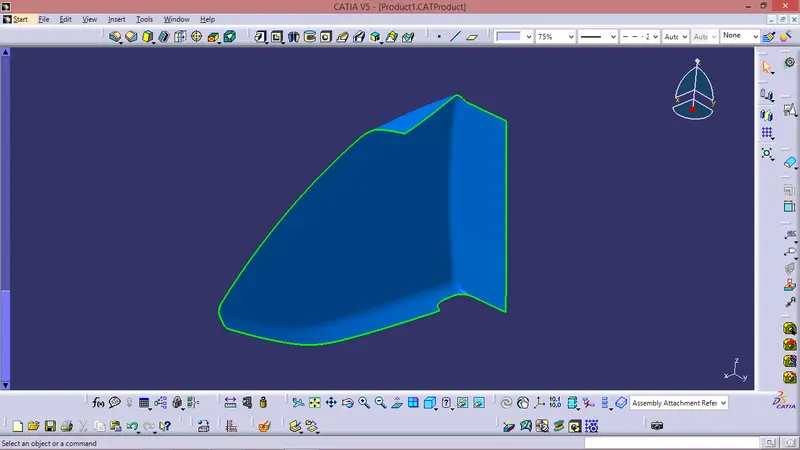
Class A Given -
Tooling Axis Creation -
Tooling direction is main consideration for plastic part and mold parts because it defines movement of mold part and possibility of plastic part to come-out from mold part (Core and Cavity).
- In Molding machine arrangement is given to open the mold along a direction which is known as Tooling Direction.
- In other words. The mold is built from two separate halves (Core and Cavity) and tooling direction basically define the direction of mold pulls apart.
- Tooling direction is known as primary direction.
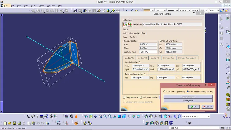
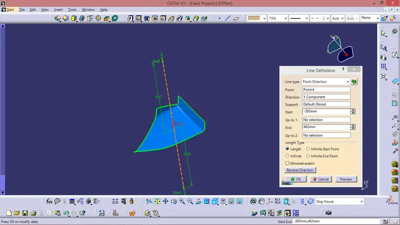
In this given Upper Map Pocket Class A surface the tooling axis is created using inertia method as shown in the fig below -
FOR CLASS B SURFACE :
- Invisible Surfaces.
- Surface mostly don't have textures
- Surface needs to be created according to the class-A surface.
- Having all features in B-side surface only.
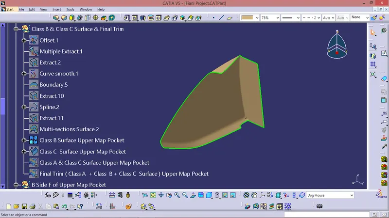
- Surfaces which is having TANGENT CONTINUITY IS CALLED class-B
Just Offseted the as per the master section & performed some modifications as per requirement.
FOR CLASS C SURFACE:
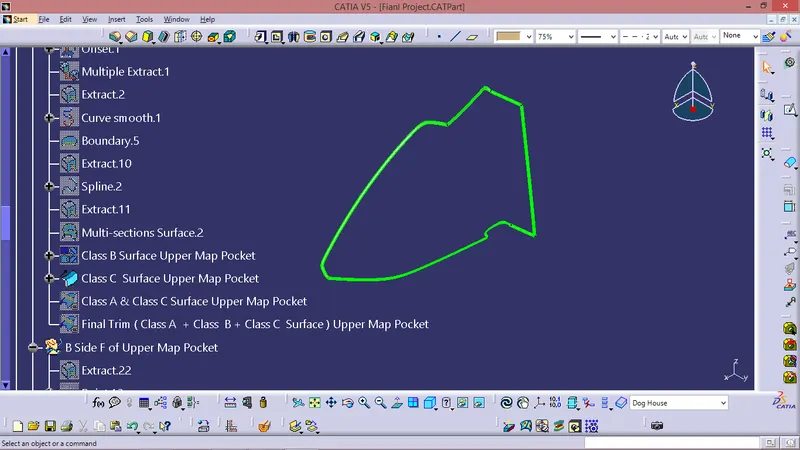
Took boundries for class A in some sections and in other sections took Multiple extract for Class A Surface.
Sweept using boundries and Multiple Extract with Reference surface.
CLASS A CLASS C TRIM
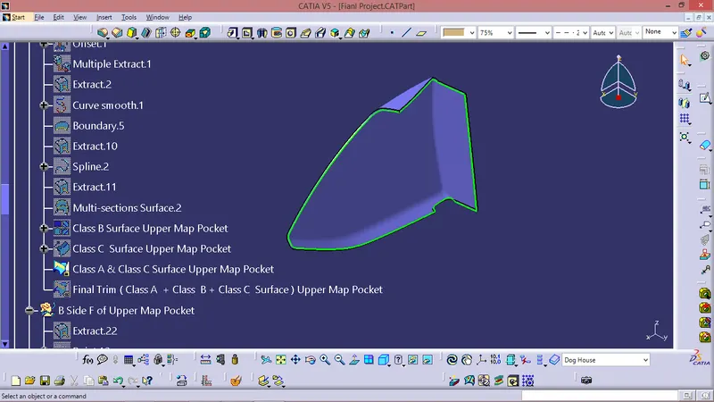
Final Trim -
Class A + Class B + Class C
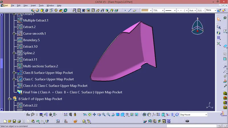
Closed Body -
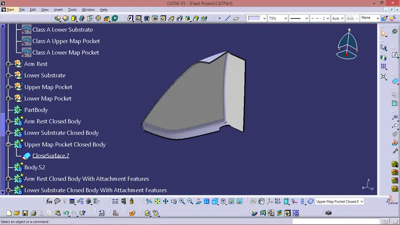
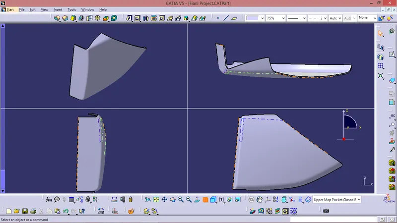
B SIDE FEATURES -
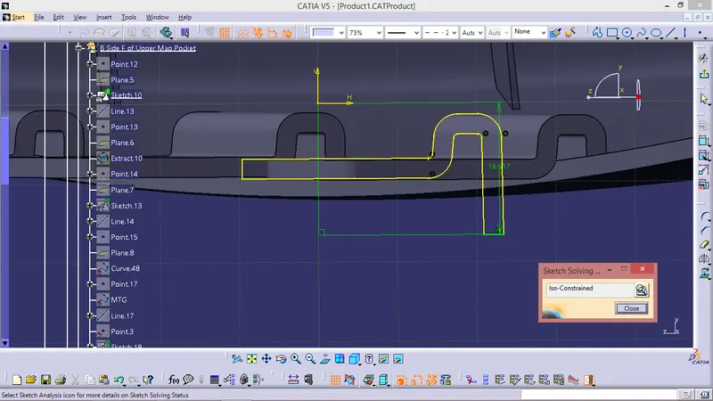
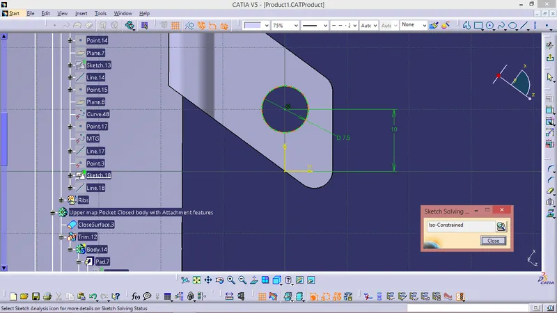
Sketch -
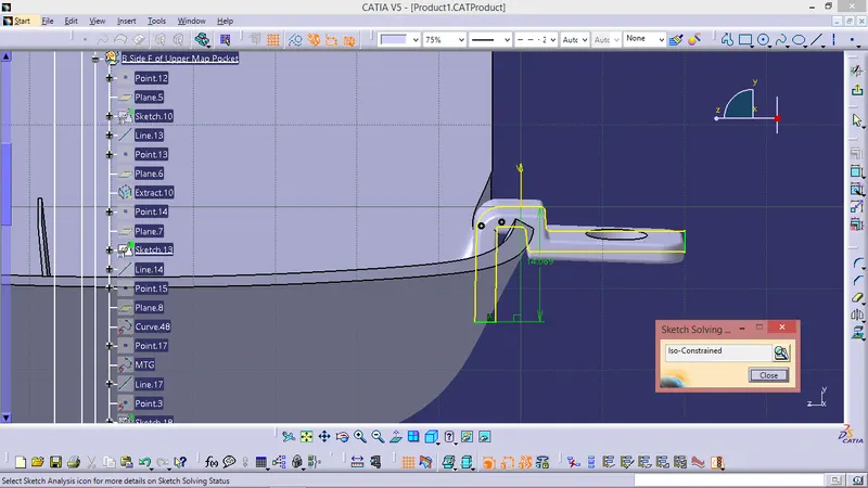
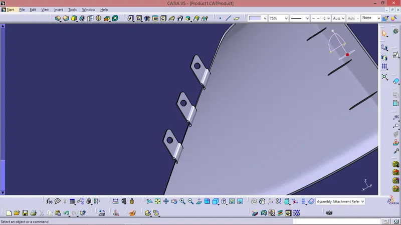
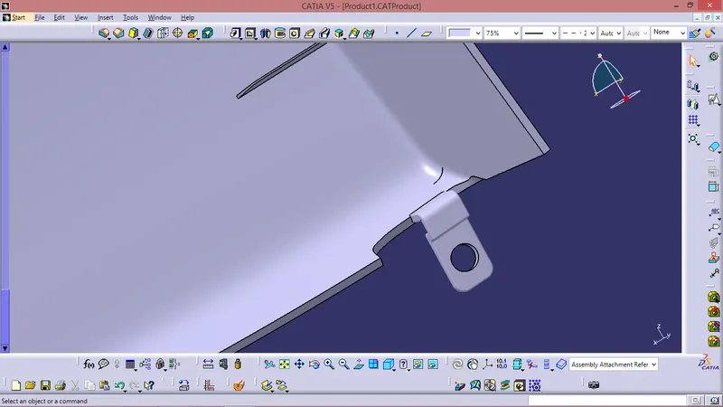
Components -
DRAFT ANALYSIS :
Class A surface draft analysis -
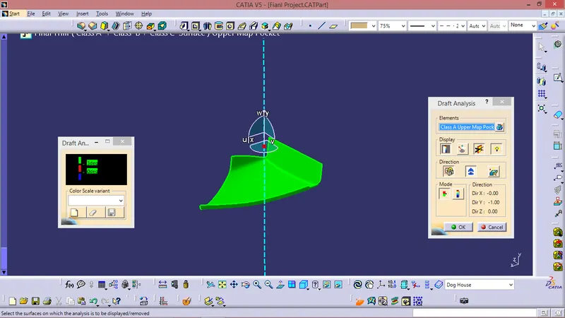
The above image shows the draft analysis in which green color surfaces shows that they are having an angle of more than 3 degrees but the surface in red color shows it is less than 3 degree. These are the results of the draft analysis which are very crucial for determining the feasibility of the product
Solid component draft analysis :
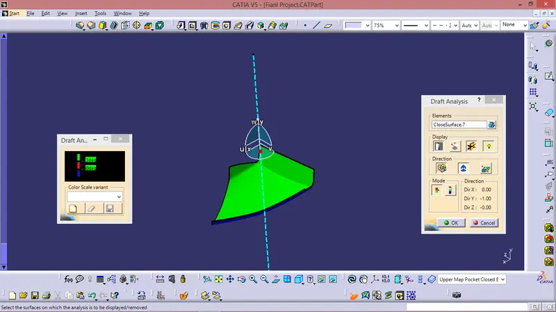
The draft analysis command enables you to detect if the part you drafted will be easily removed. This type of analysis is performed based on colour range identifying zones on the analysed element where the deviation from the draft direction at any point, corresponds to specified values. After draft analysis done we can observe that the green colour shows that the drafted walls of the switch bezel are above 3 degrees which is a permissible criteria to manufacture in injection moulding.
Draft Analysis. For Final Closed Body With Attachment Features -
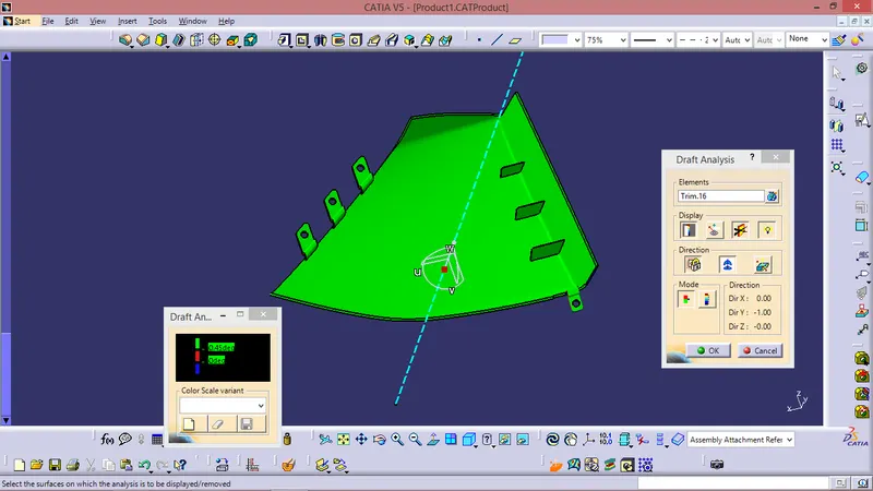
- Draft analysis is done on the final part with the tooling axis as reference
- Green surface indicates the areas where the draft is more than 0.5 degrees.
- Blue surface indicates the area having negative draft.
Closed Body With Attachment Features -
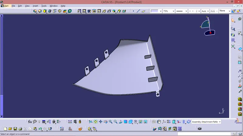
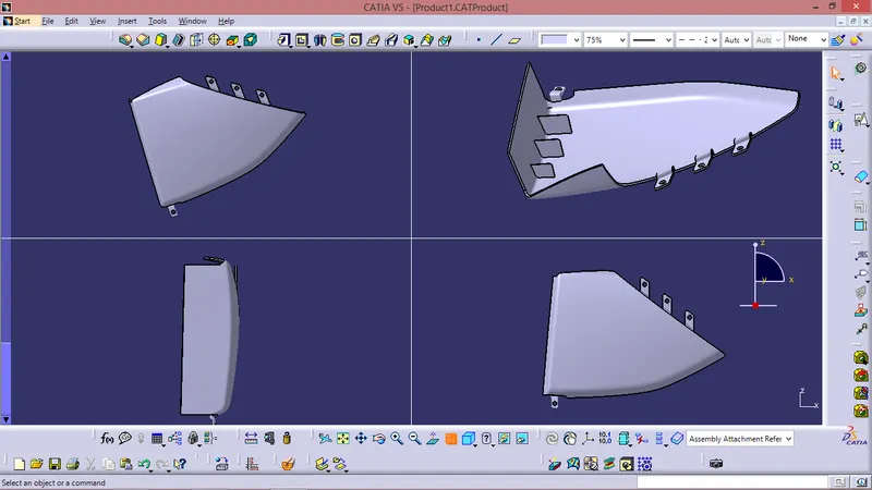
TREE STRUCTURE :
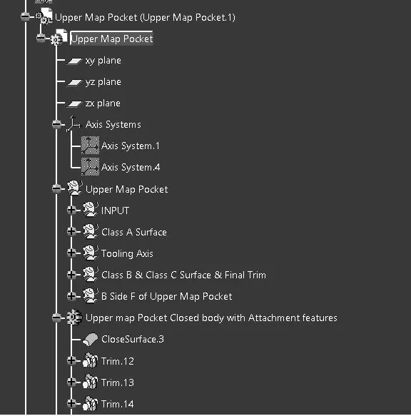
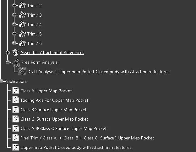
LOWER MAP POCKECT
Class A given -
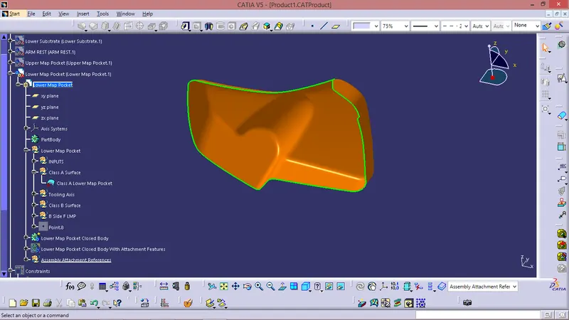
Tooling Axis Creation -
Tooling direction is main consideration for plastic part and mold parts because it defines movement of mold part and possibility of plastic part to come-out from mold part (Core and Cavity).
- In Molding machine arrangement is given to open the mold along a direction which is known as Tooling Direction.
- In other words. The mold is built from two separate halves (Core and Cavity) and tooling direction basically define the direction of mold pulls apart.
- Tooling direction is known as primary direction.
There are two methods to create Tooling Axis -
- Bisecting method &
- Inertia method
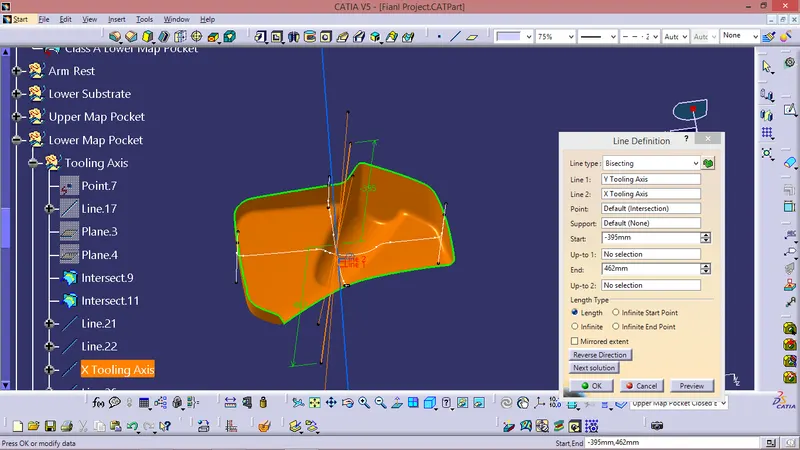
For this Component Tooling Axis is created by Bisecting method -
- By taking Extract of the base and creating a point on centre of the extact and then creating axis system or plane on that point .
- Intersecting the Class A with the point .
- Creating bisecting line using the extracts on the intersection .
- Checking the tooling axis created is clearing all the sides of the Class A by keeping it in Normal view mode.
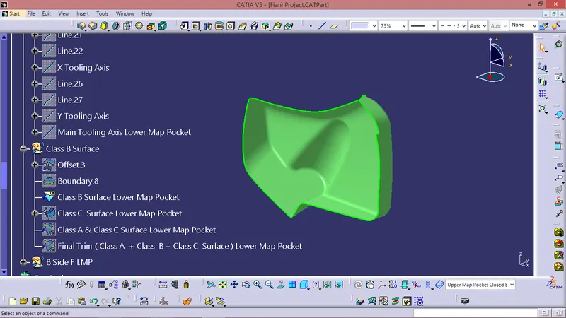
FOR CLASS B SURFACE :
- Invisible Surfaces.
- Surface mostly don't have textures
- Surface needs to be created according to the class-A surface.
- Having all features in B-side surface only.
- Surfaces which is having TANGENT CONTINUITY IS CALLED class-B
Just Offseted the as per the master section & performed some modifications as per requirement.
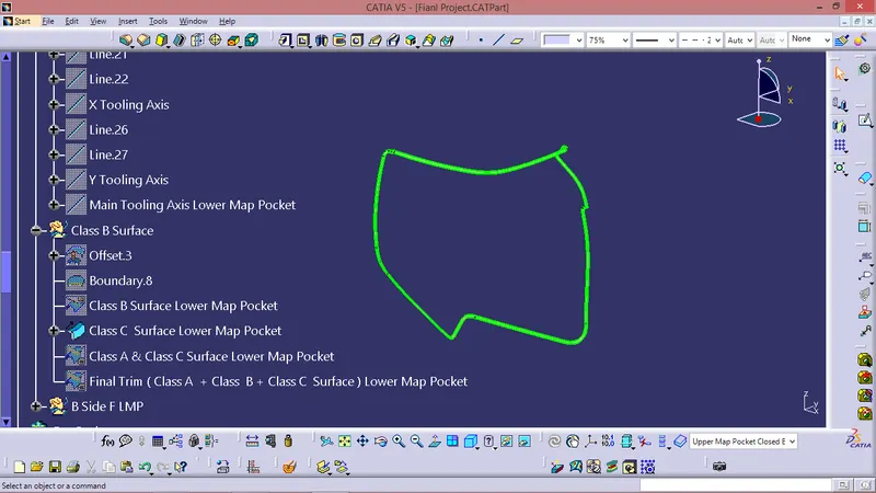
FOR CLASS C SURFACE:
Took boundries for class A in some sections and in other sections took Multiple extract for Class A Surface.
Sweept using boundries and Multiple Extract with Reference surface.
CLASS A CLASS C TRIM
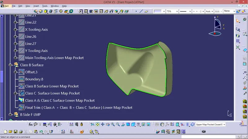
Final Trim -
Class A + Class B + Class C
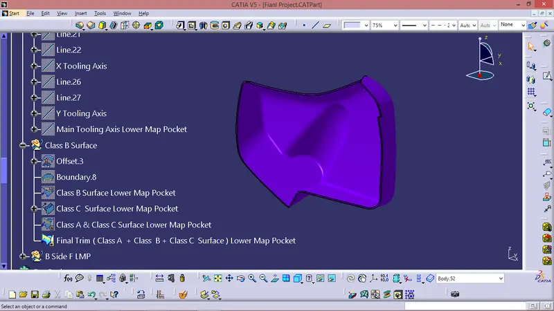
Closed Body -
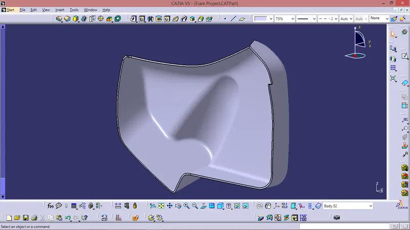
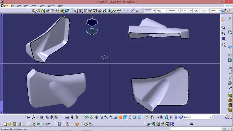
B SIDE FEATURES -
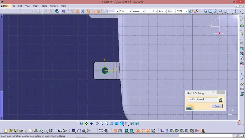
Sketch -
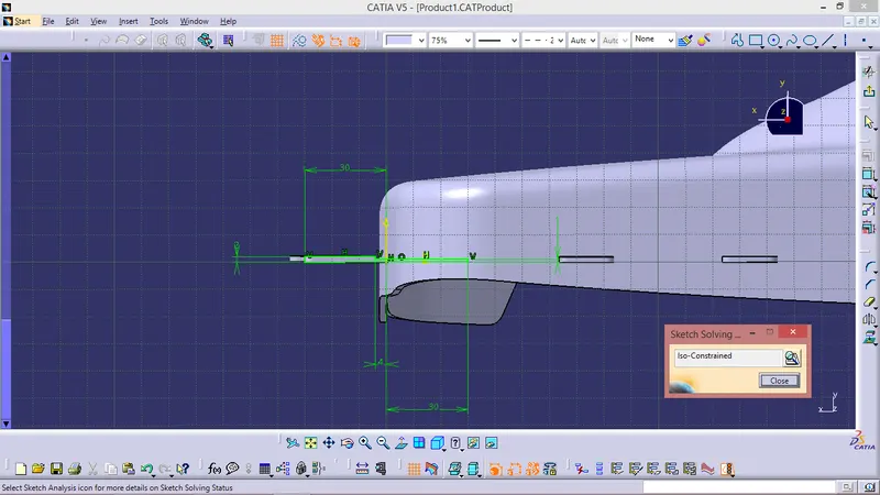
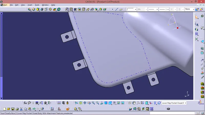
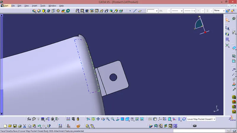
Component -
DRAFT ANALYSIS :
Class A surface draft analysis -
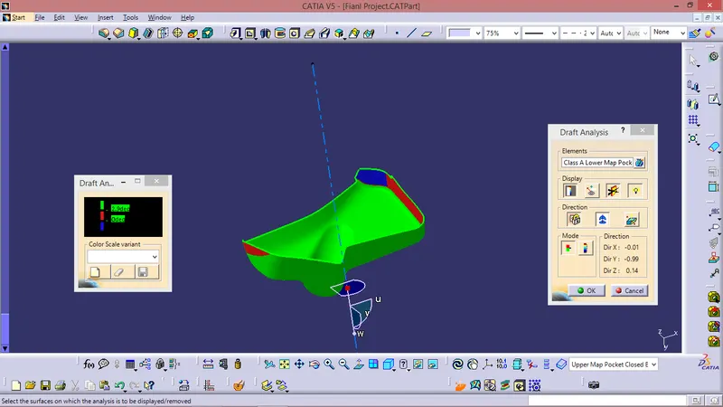
The above image shows the draft analysis in which green color surfaces shows that they are having an angle of more than 3 degrees but the surface in red color shows it is less than 3 degree. These are the results of the draft analysis which are very crucial for determining the feasibility of the product
Solid component draft analysis :
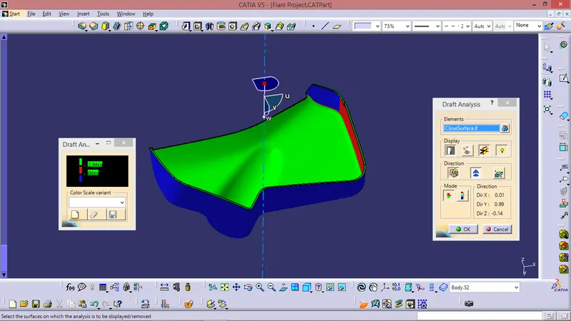
The draft analysis command enables you to detect if the part you drafted will be easily removed. This type of analysis is performed based on colour range identifying zones on the analysed element where the deviation from the draft direction at any point, corresponds to specified values. After draft analysis done we can observe that the green colour shows that the drafted walls of the switch bezel are above 3 degrees which is a permissible criteria to manufacture in injection moulding.
NOTE - Some patches on the Class A surface was 0 deg draft same has been reflected on the Closed Body.
Draft Analysis. For Final Closed Body With Attachment Features -
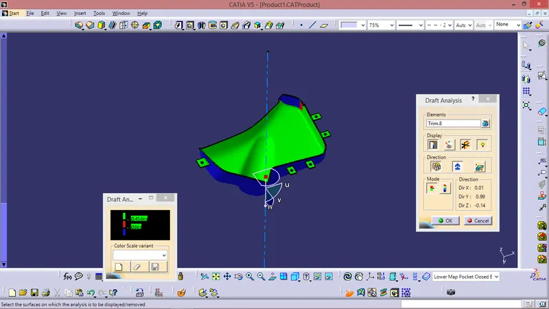
- Draft analysis is done on the final part with the tooling axis as reference
- Green surface indicates the areas where the draft is more than 0.5 degrees.
- Blue surface indicates the area having negative draft.
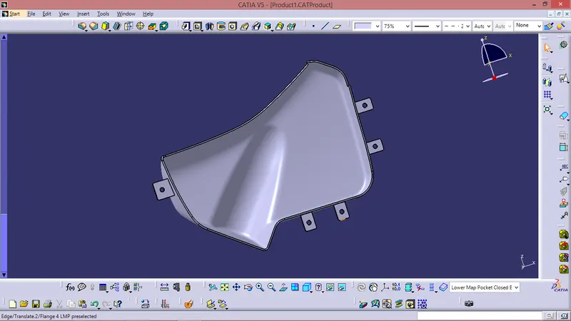
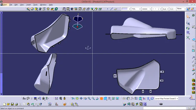
Closed Body With Attachment Features -
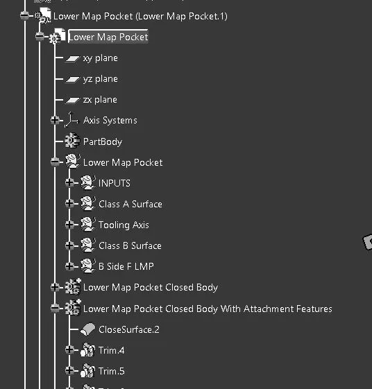
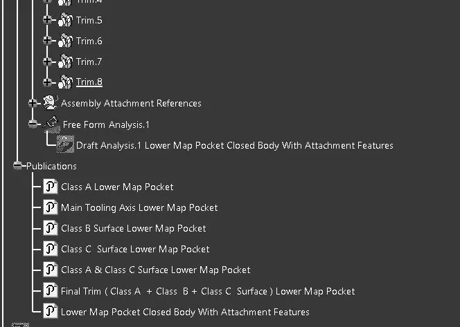
TREE STRUCTURE :
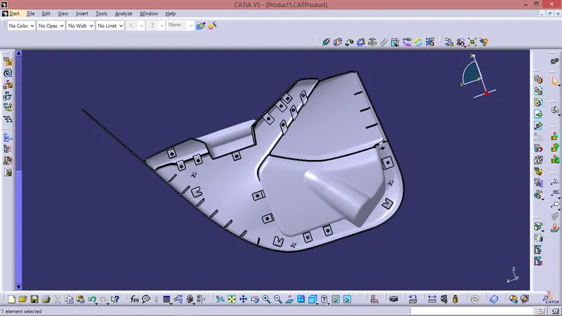
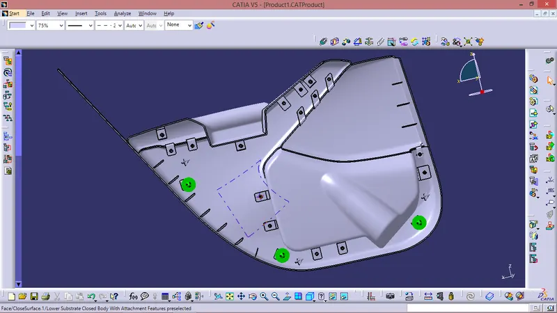
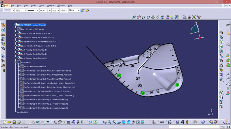
FINAL ASSEMBLY -
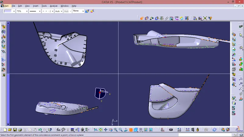
After Attaching Push pins -
PUSH PINS ARE USED TO ATTACH THE PLASTIC PART TO THE SHEET METAL PART .
CONCLUSION
The door panel successfully designed by following all design rules used in automotive industry. All the attachment feature are properly placed at different location.