Week 8 - Challenge 6 - Core & Cavity Design
CORE AND CAVITY BLOCKS FOR SWITCH BEZEL COMPONENT
Aim / Objective :
- To Create the Core and cavity blocks for the switch bezel component.
FOR TOOLING AXIS :
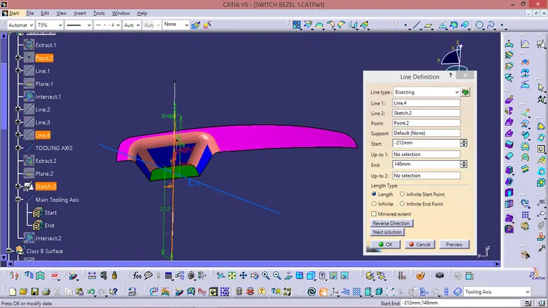
It is nothing but the direction in which the mould opens and closes the draft angle needed to be provided by considering this tooling axis. We can create a tooling axis by using the bisecting method. This method is used for the generation of the tooling axis for that purpose first we need to decide the direction of moulding and then we create one dummy tooling axis for the reference to the purpose. In this method, we select the surfaces which can create problems and take intersections in the x and y-direction. By using these curves we draw two lines and then draw a bisecting line from these two lines in the x-direction and y-direction. If it is done in x-direction then it is called a tooling axis clearing x-direction and if in y then tooling axis clearing y-direction. After completing this we need to draw a final line bisecting this two tooling axis in the X and Y directions to get our final output.
DRAFT ANALYSIS :
Class A surface draft analysis:
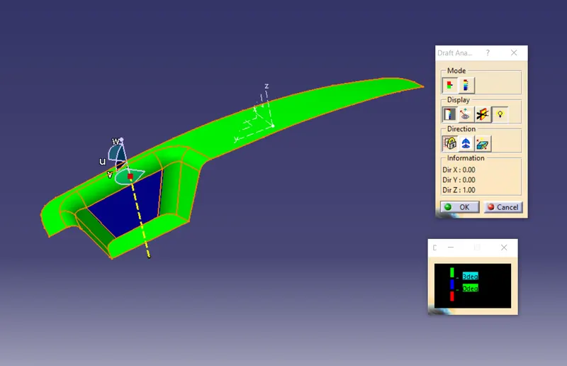
The above image shows the draft analysis in which green color surfaces shows that they are having an angle of more than 3 degrees but the surface in red color shows it is less than 3 degree. These are the results of the draft analysis which are very crucial for determining the feasibility of the product
Solid component draft analysis:
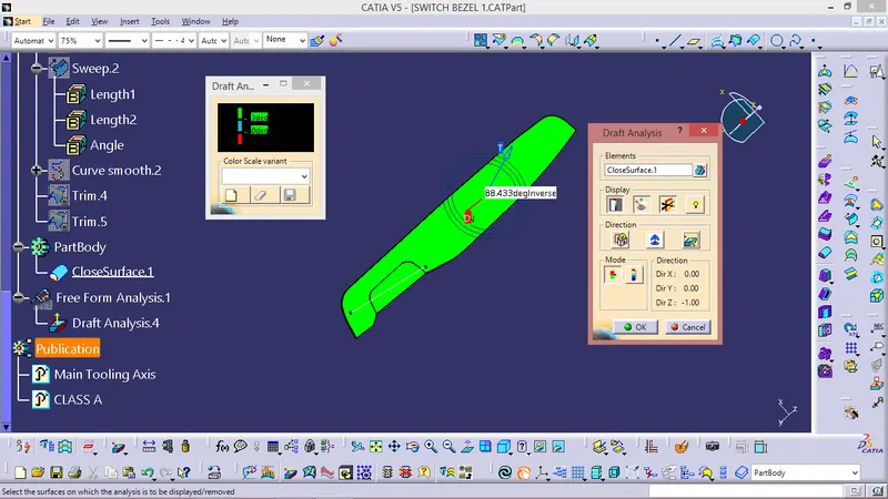
The draft analysis command enables you to detect if the part you drafted will be easily removed. This type of analysis is performed based on colour range identifying zones on the analysed element where the deviation from the draft direction at any point, corresponds to specified values. After draft analysis done we can observe that the green colour shows that the drafted walls of the switch bezel are above 3 degrees which is a permissible criteria to manufacture in injection moulding.
CORE AND CAVITY DESIGN -
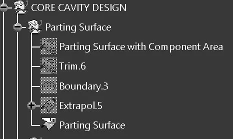
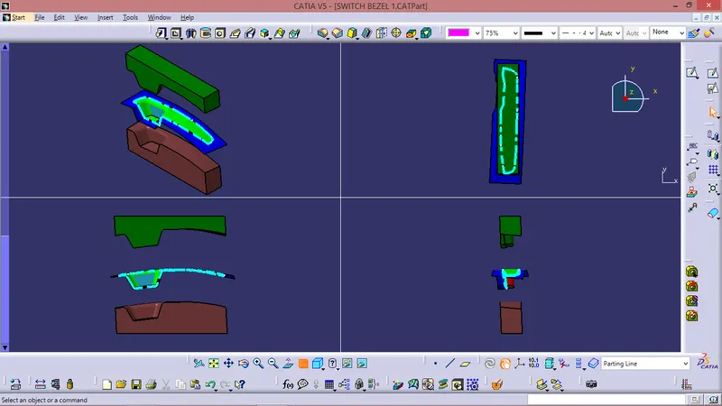
- Parting Surface
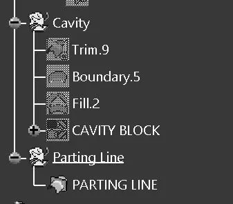
- Parting line
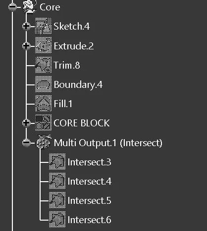
- CORE Block
- CAVITY Block
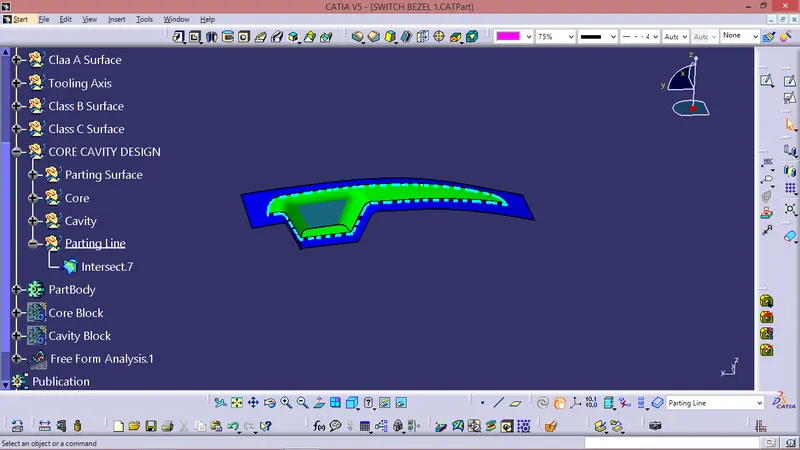
PARTING SURFACE
- Designed for the removal of the plastic product and the cold slug, the parting surface is where the core meets the cavity, and usually locates at the largest section of a product.
- Blue colour surface shown in pic is the parting surface
PARTING LINE -
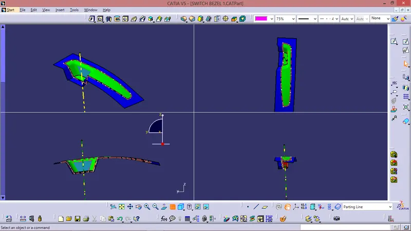
- The parting line is where the two halves of the mold meet around the parameter of the part. All parting lines need to seal properly when the mold is clamped in a molding machine.
- Cyient dotted line shown in figure is parting line.
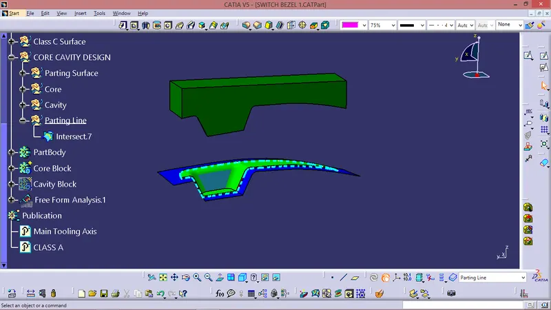
CORE DESIGN -
- Core - A portion of the mold that goes inside a cavity to form the interior of a hollow part.
- Core-cavity - A term used to describe a mold created by mating A-side and B-side mold halves.
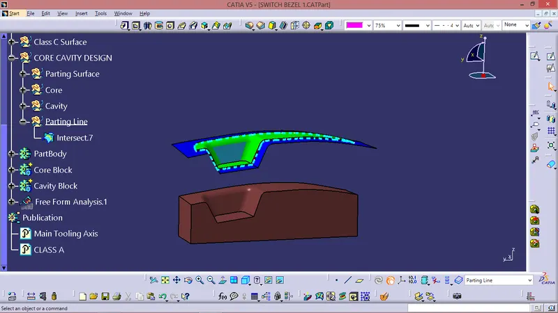
CAVITY DESIGN -
- A mold is a hollow form typically made from stainless steel that has plastic injected into it to manufacture a plastic part.
- The plastic is inserted into the mold cavity, which is a hole in the mold shaped like the desired part.
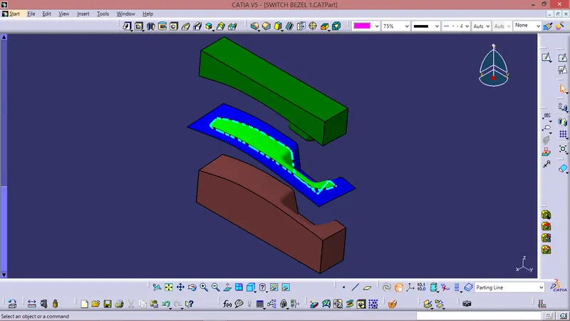
ISOMETRIC VIEW
SOME COMMON VIEWS
PUBLICATIONS
- Publication is done to the component to make it visible and navigate easily.
- To publish the component go to tools > publications and then select the tooling axis and the class A surface.
- A separate tree structure is formed under the main part.

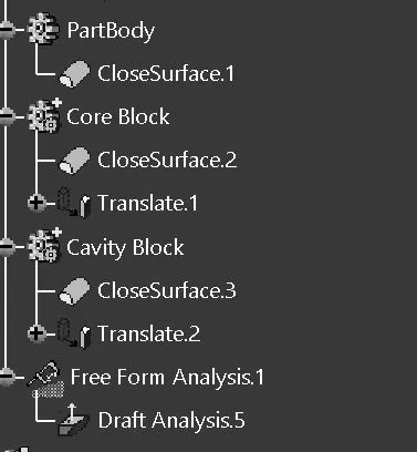
TREE STRUCTURE -