Week 8 - Challenge 2 - Switch Bezel Design
SWITCH BEZEL
Aim / Objective : To design a model using Class A Surface after extraction by using Surface Workbench .
Introduction :
Class A Surface : An aesthetic and outermost surface which is made by the plastic designer and is given as an input to the plastic modeler to workon it .
Class B Surface : A surface below a certain thickness from the Classa surface is known as Class B surface .It is also known as engineering surface .
Class C Surface : The surface that joins the Class A surface and Class B surfaceis known as Class C surface .
Methodology :
In this design we will focus on the following steps
- Tooling Axis
- Draft Analysis
- Class B Surface
- Class C Surface
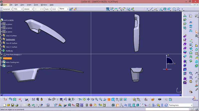
- Making a solid model from Class A surface
Following tools were used to reach the final Solid Model :
- Extract
- Un - trim
- Trim
- Offset
- Extrapolate
- Boundary
- Edge Fillet
- Sweep
- Join
- Close Surface ( Part Design )
FOR TOOLING AXIS :
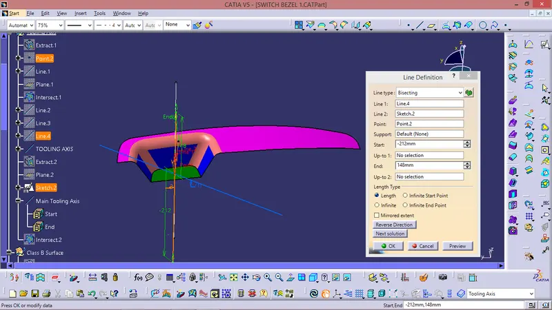
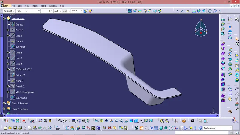
It is nothing but the direction in which the mould opens and closes the draft angle needed to be provided by considering this tooling axis. We can create a tooling axis by using the bisecting method. This method is used for the generation of the tooling axis for that purpose first we need to decide the direction of moulding and then we create one dummy tooling axis for the reference to the purpose. In this method, we select the surfaces which can create problems and take intersections in the x and y-direction. By using these curves we draw two lines and then draw a bisecting line from these two lines in the x-direction and y-direction. If it is done in x-direction then it is called a tooling axis clearing x-direction and if in y then tooling axis clearing y-direction. After completing this we need to draw a final line bisecting this two tooling axis in the X and Y directions to get our final output.
FOR CLASS B SURFACE :
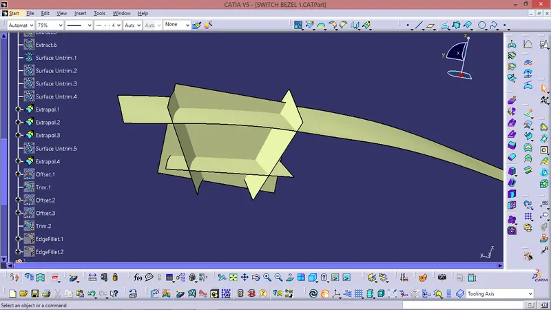
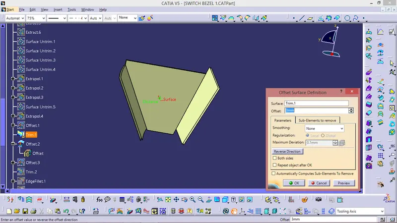
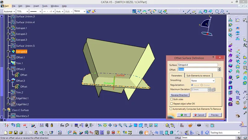
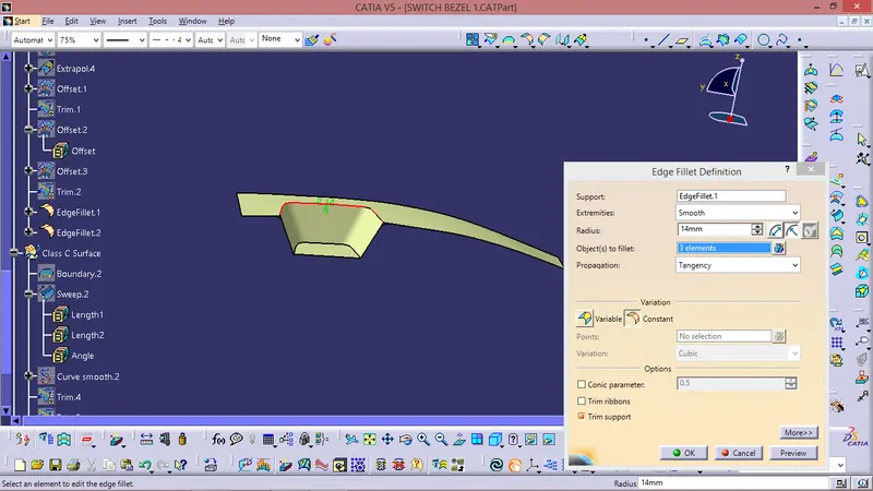
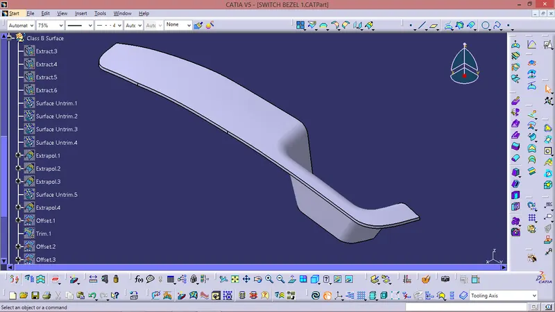
- The class B surface is created by extracting each surface of class A surface and then un trimming them.
- After the an offset of 3 mm is given in the downward direction to generate the class B surface
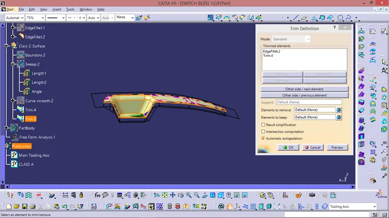
- The surface are then extrapolated with a certain distance in order to create cross section among the surfaces to perform trim operation. Surface trim option was used to give the class B surface required shape
FOR CLASS C SURFACE :
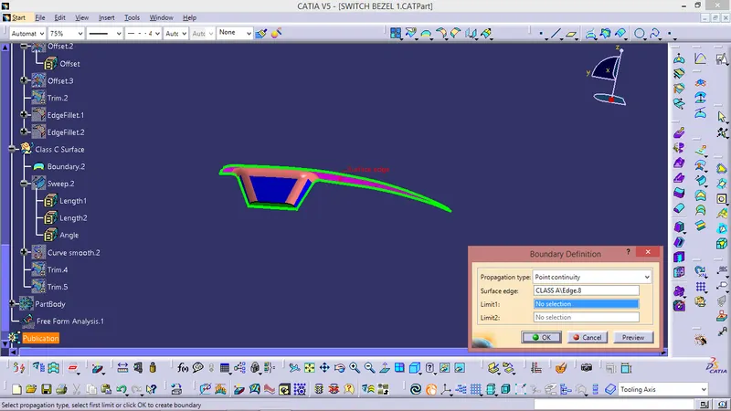
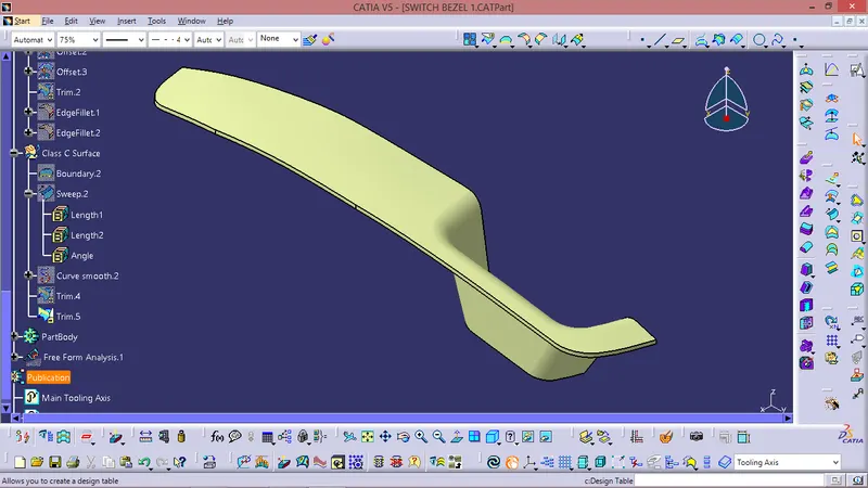
- For the creation of class B surface first the boundary of the class A surface is extracted using BONDARY feature and if the surface has more patches then it is smoothen eith SMOOTH SURFACE COMMAND and it is used to create a sweep.
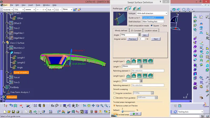
- After the sweep option is used to create the sweep along the tooling axis direction.
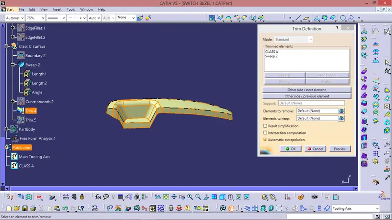
- Class A Surface and the Class C Surface are then trimmed together to get desired shape
- After this operation trim of Class A & Class C surface are trimmed with the Class B surface to give the plastic product a mouldable shape.
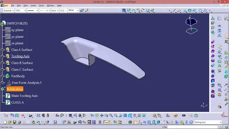
- After ensuring that the surfaces formed are completely closed, the closed surface feature is used to create the solid mould of the switch bezel.
FINAL TRIM :
DRAFT ANALYSIS :
Class A surface draft analysis:
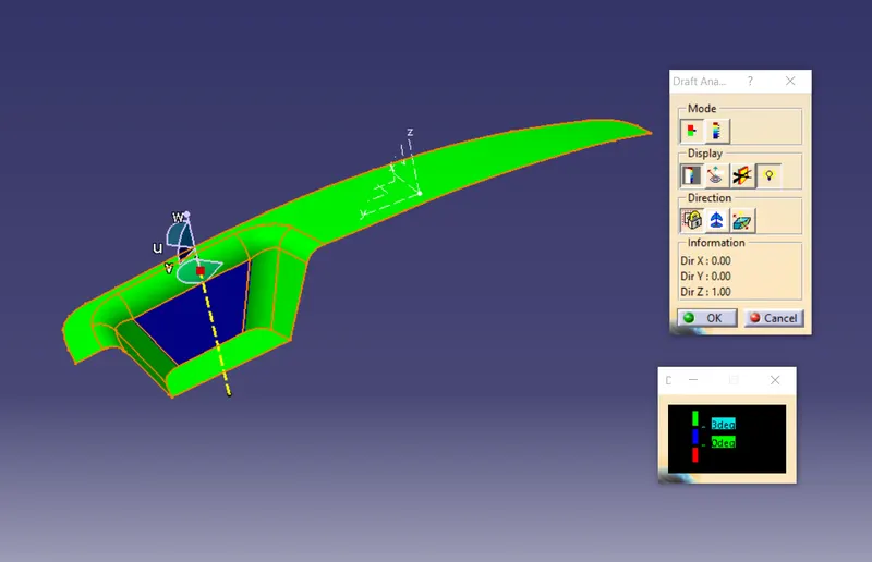
The above image shows the draft analysis in which green color surfaces shows that they are having an angle of more than 3 degrees but the surface in red color shows it is less than 3 degree. These are the results of the draft analysis which are very crucial for determining the feasibility of the product
Solid component draft analysis:
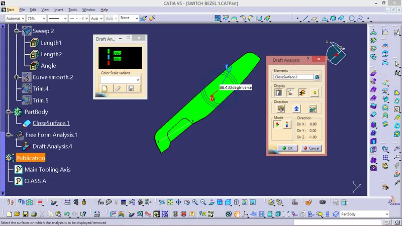
The draft analysis command enables you to detect if the part you drafted will be easily removed. This type of analysis is performed based on colour range identifying zones on the analysed element where the deviation from the draft direction at any point, corresponds to specified values. After draft analysis done we can observe that the green colour shows that the drafted walls of the switch bezel are above 3 degrees which is a permissible criteria to manufacture in injection moulding.
Solid Mould :
TREE STRUCTURE :
CONCLUSION :
- Class A, Class B and Class C surfaces are created following standards of automotive industry using Catia V5 software
- Draft analysis was performed on the switch bezel and it was observed that draft was under permissible limit for the manufacturing of the component using injection moulding process.