Week 11 - Final project
Final project
Development of a Door Trim panel
AIM: Creation of CAD model considering following inputs as like in OEM and tier1 companies
- a) Class A surface
- b) Nominal thickness: Refer to master sections
- c) Attachment strategy :
Use Pushpin with Dog house for Lower substrate – Door panel attachment
Use heat stakes for a part of the part attachment.
ABSTRACT:
The project explains the steps and procedures followed while developing the Door Trim Panel of a car using CATIA V5. The class A surface tooling axis, class B surface, and class C surface were created, and after forming the solid body from that the flanges and the B side features such as Dog house, push pins, Heat stakes, etc were built. And finally, the draft analysis is also done on the components to check the manufacturability of the features.
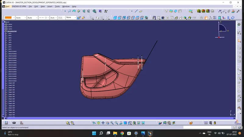
1. LOWER SUBSTRATE:
Class A and Tooling axis:
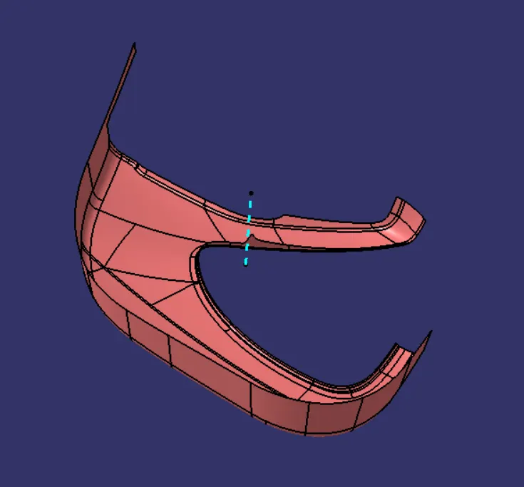
Multiple extracted the subparts of the surface for lower substrate and created a single class A surface using the join command. Some parts were not properly aligned so joining base and sub-elements to remove that part and using a multi-section surface to create a class A surface with no defects.
- Create a point on the class A surface to move the main tool for component creation on the base surface.
- Mask an axis over the point created with the same directions as the main axis.
- Using Intersect command from Generative Shape design select the YZ plane as the first element and the class A surface as the second element.
- After creating the intersecting lines select the Line command and join the vertices which show the most possible draft angle manufacturable.
- Bisect those two lines over the axis point we created.
Draft analysis:
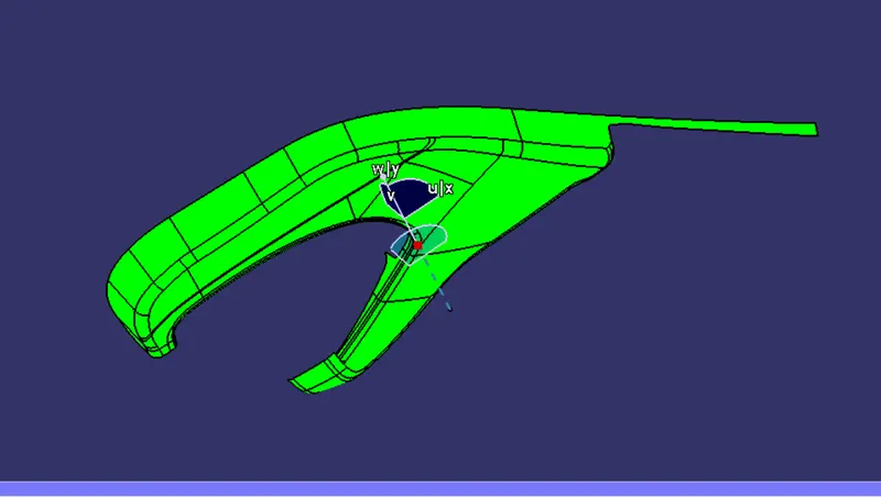
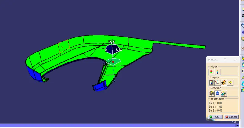
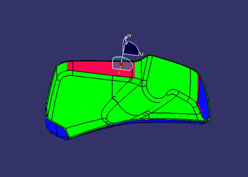
- After Tooling Axis Select the Feature Draft Analysis option from the Insert Option.
- Select the element to analyze.
- Next click on Use the compass to define the new current draft direction option and make it align with the tooling axis by dragging it to the axis.
- If the color appears blue click the invert option on the right side of the draft direction axis button.
Class B:
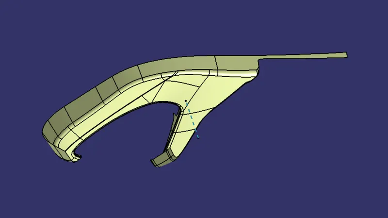
Using the Offset command and taking reference from the master section provided an offset of 2.5mm is given for the thickness of the part.
Since fillets were creating problems for surface creation so by using the multi-section surface command the remaining surfaces were created.
Class C:
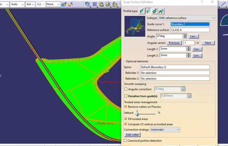
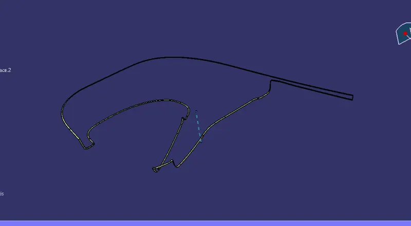
Here all the outer boundaries are extracted according to the requirements.
Using the sweep command with the draft direction of 3 degrees we get the CLASS C surface.
the sweep was created in patches as connectivity error was occurring each sweep was extrapolated and trimmed together to create one single class C surface.
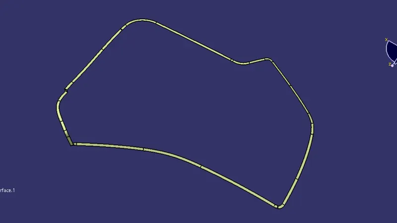
Final trim:
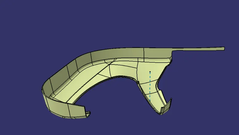
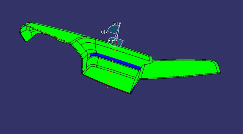
Finally, all surfaces were trimmed together as shown below.
Draft analysis
Above class A was draft analyzed here also after creating a closed surface body, the draft analysis is done.
Similar to the above process all class A, tooling axis, B, C, and, Final trims are created for all the other surfaces.
2. OUTER MAP POCKET:
Class A and tooling Axis:
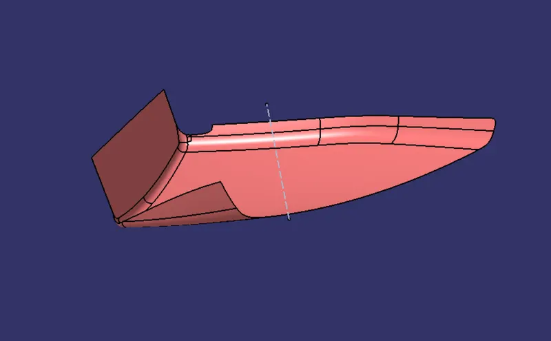
Draft analysis of class A
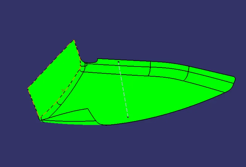
Class B
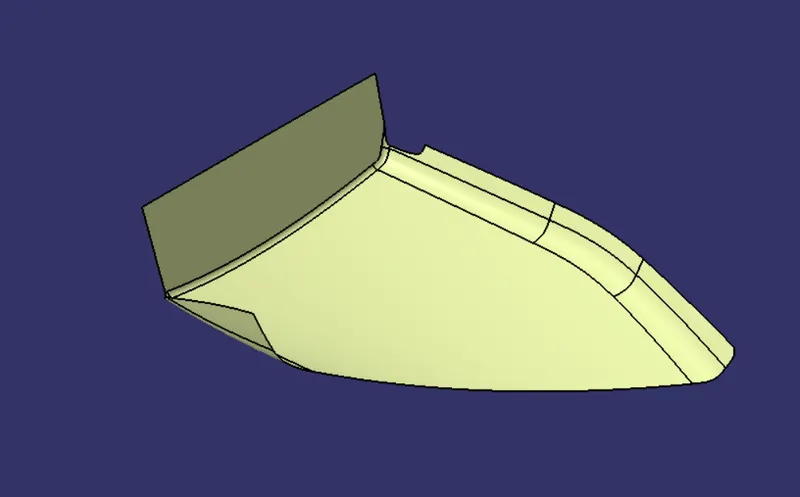
Class C
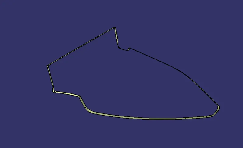
Final trim:
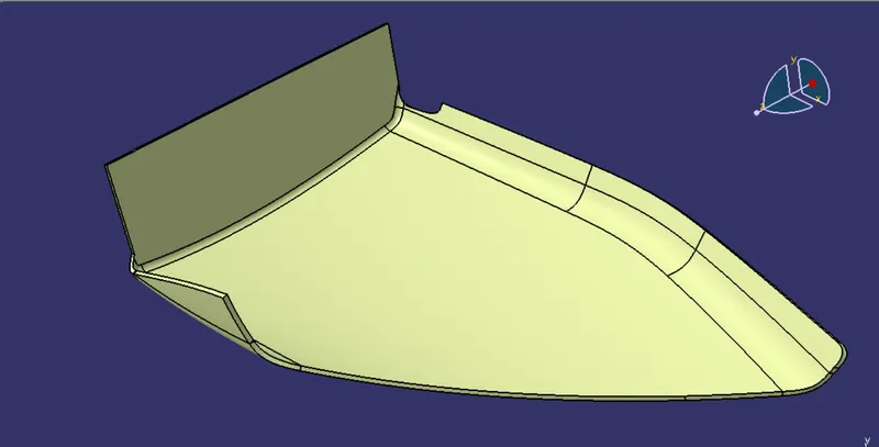
Draft analysis:
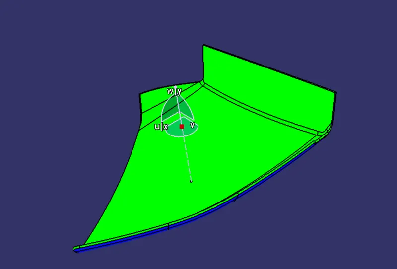
3. Bottle Holder:
Class A and tooling axis:
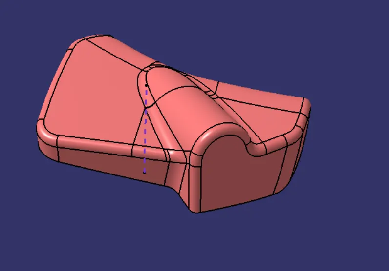
Draft analysis:
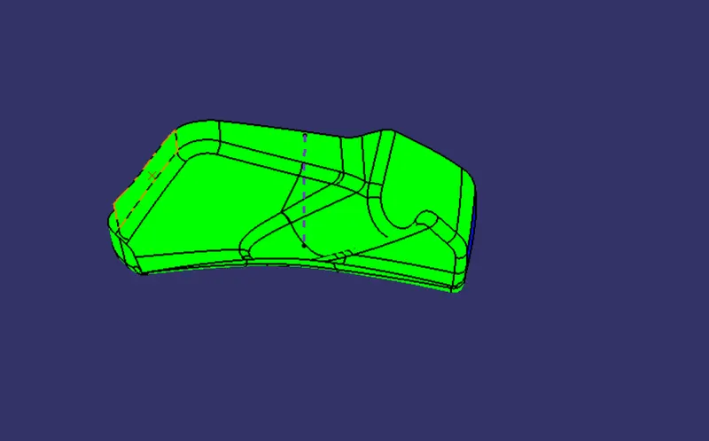
Class B
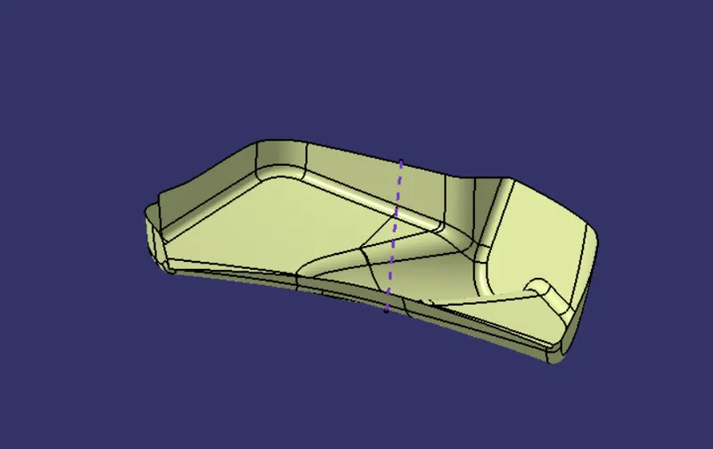
Class C
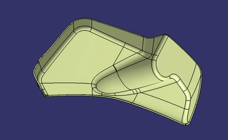
Final trim
Draft analysis
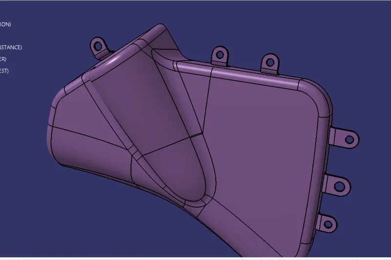
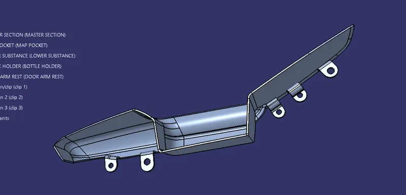
4. DOOR ARMREST:
Class A
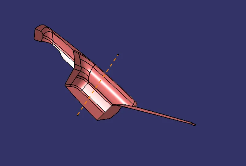
Draft analysis:
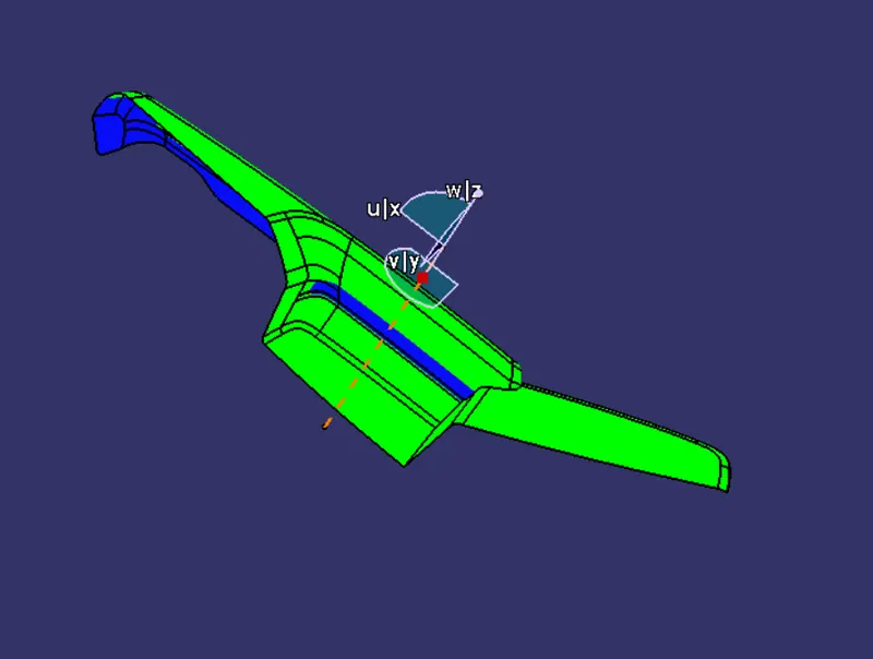
Class B
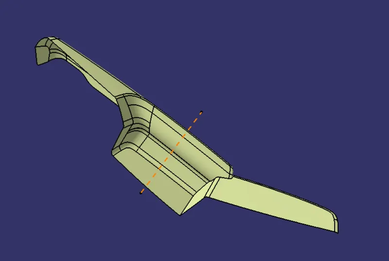
Class C
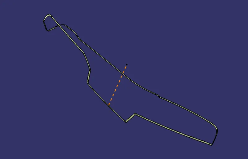
Final trim
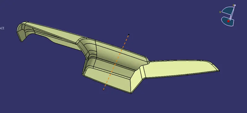
Draft analysis
MOUNTING FEATURES AS PER DESIGN GUIDELINES:
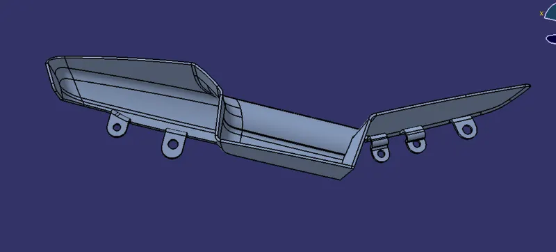
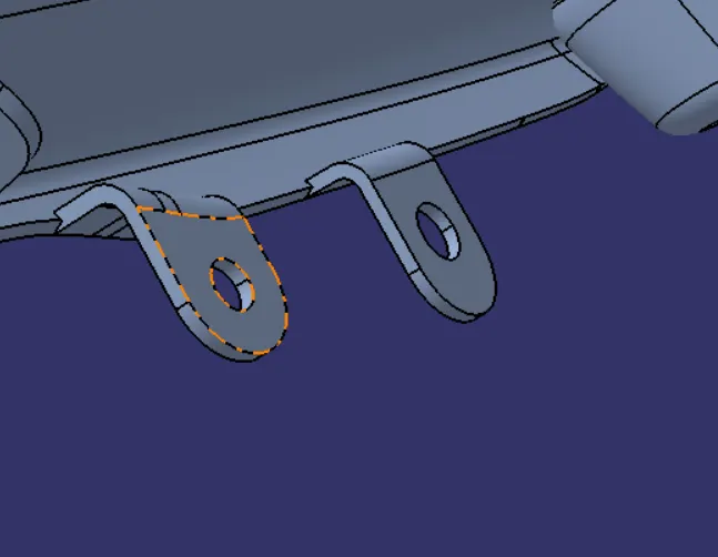
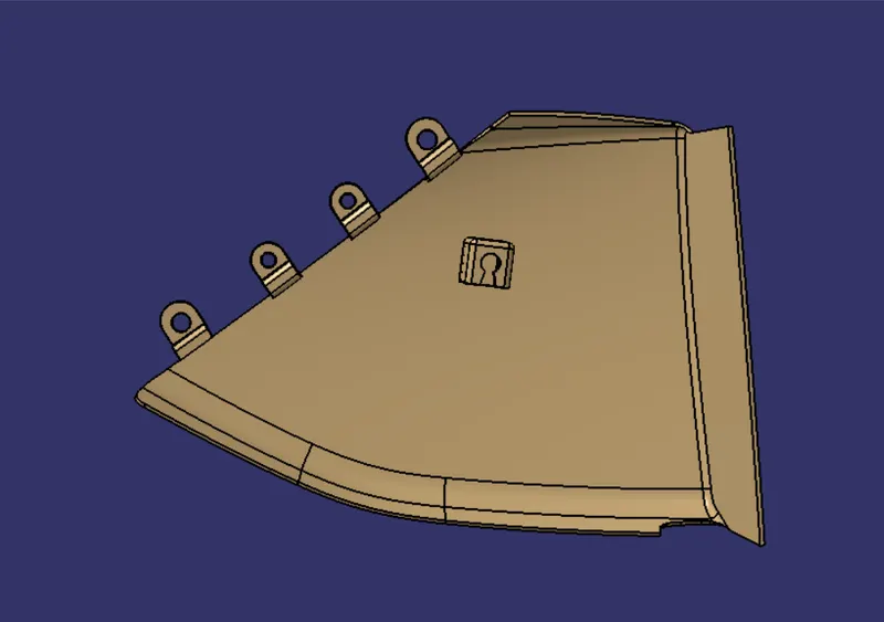
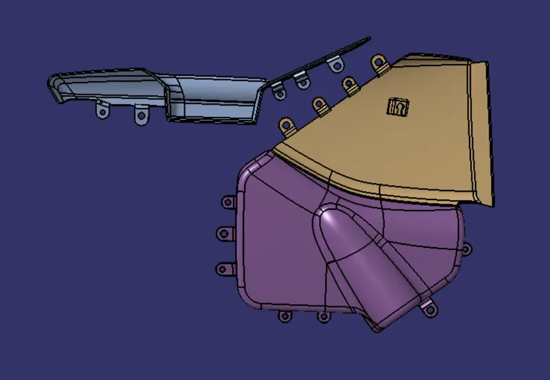
FLANGES:
A flange is a protruded ridge, lip, or rim, either external or internal, that serves to increase strength (as the flange of an iron beam such as an I-Beam or a T-beam); for easy attachment/transfer of contact force with another object.
DOG HOUSE:
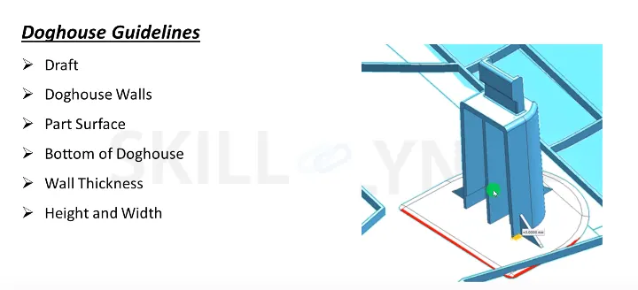
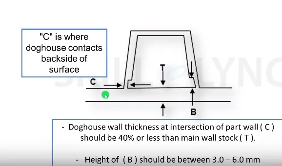
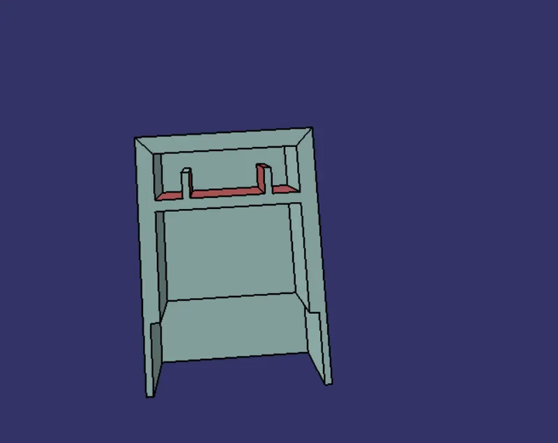
The dog house is an engineering feature used in the plastic trim design. Dog houses are used as supporting features. Sometimes other engineering features like snaps; locators, etc. are mounded on them to increase their strength.
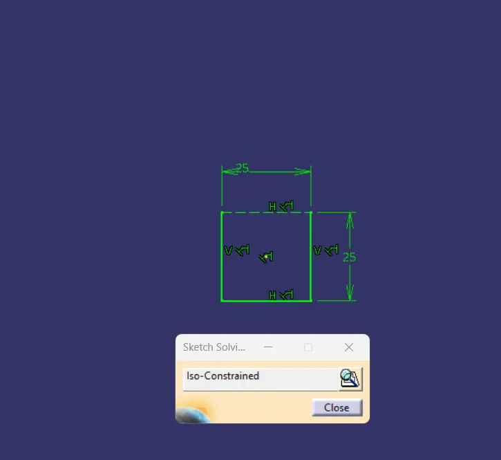
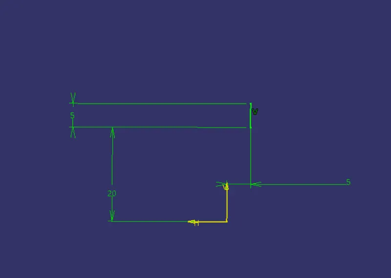
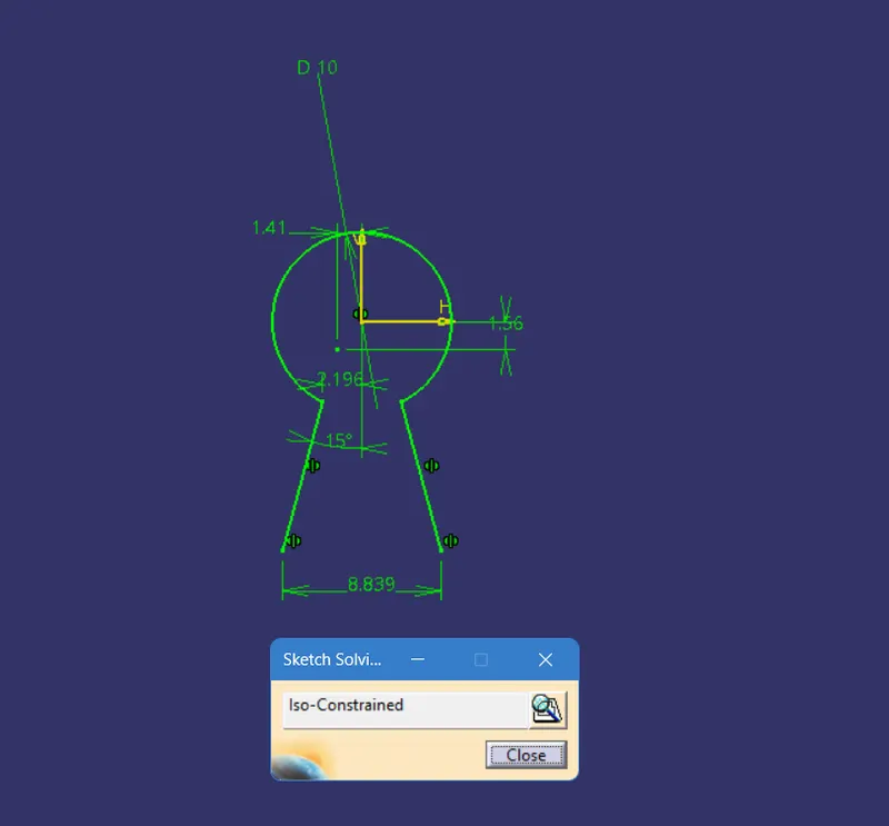
- Draft 1.5 degrees on all walls
- The intersection of part wall Thickness= 0.4* T
- Height =3<->6mm
- Width of dog house =12 mm
- Fillet value 0.25mm
Sketches:
PART BODY:
The sketch is swept in the draft direction at 1.5 degrees.
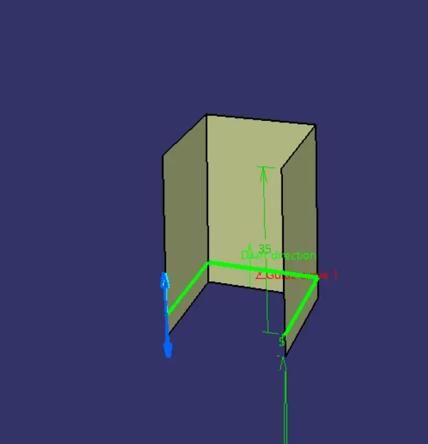
The base surface is offset and trimmed to form a cube with no front face.
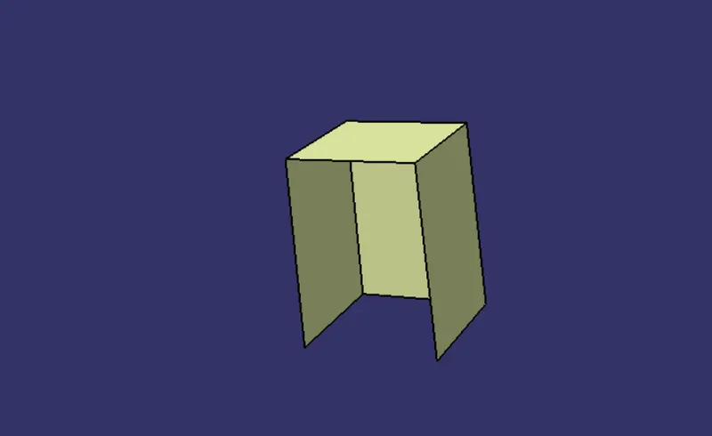
A thick surface is given in the Part design.
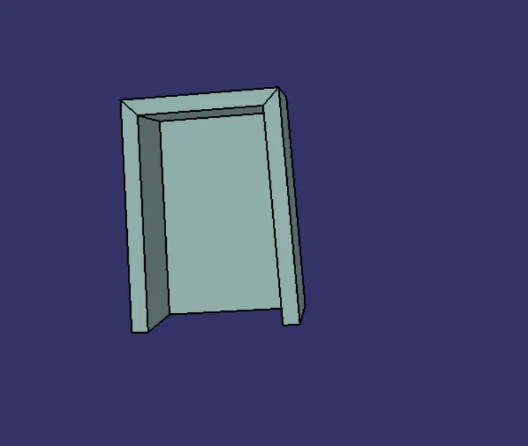
To create coring 1mm width and 4mm height are selected inside the dog house created.
Offset the base to 3mm and trim it with the original sweep to create a box.
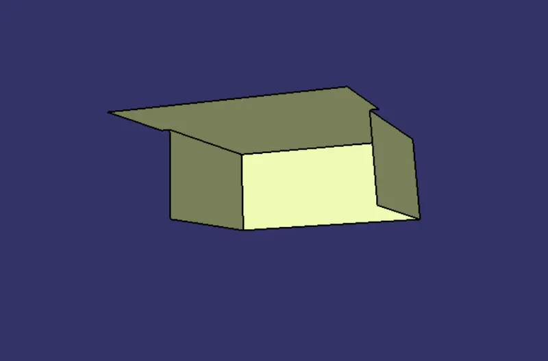
Using a thick surface gives 1 mm outward extrusion, and using the remove command cut the part from the main dog house body.
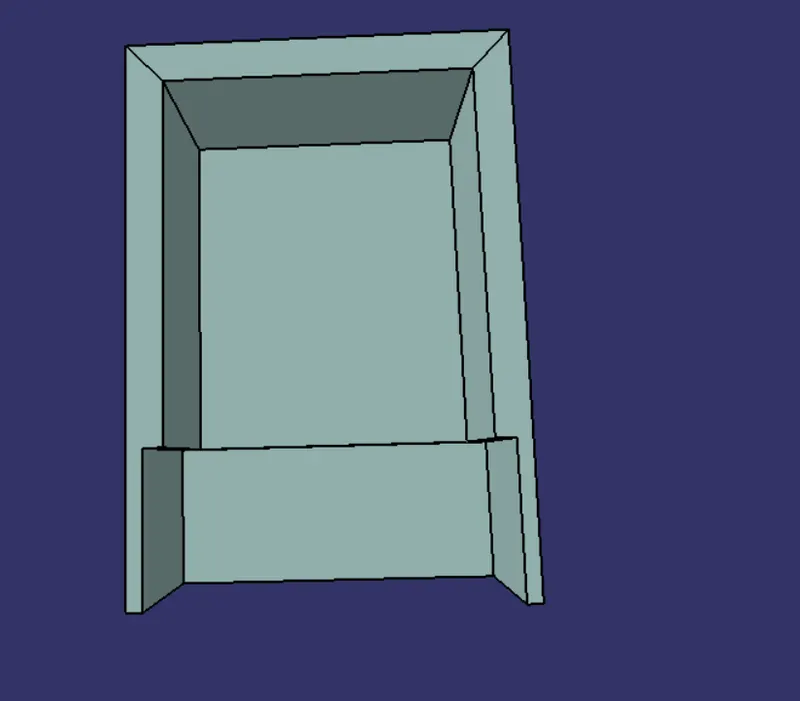
Ribs are created for the easy fitting of pushpins.
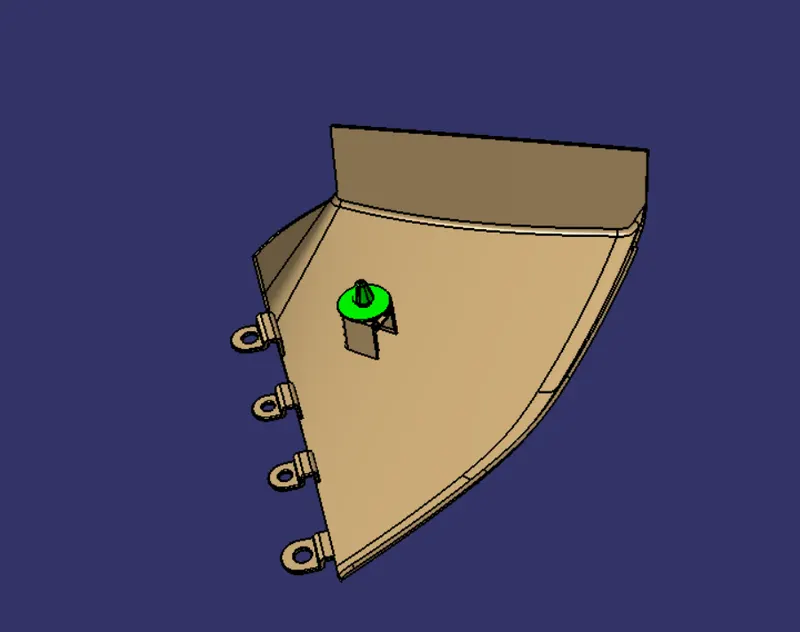
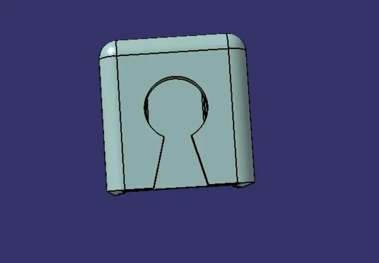
A hole for the pushpin is needed so according to the sketch the surface is extracted and split with the dog house to create the hole for pushpin fit.
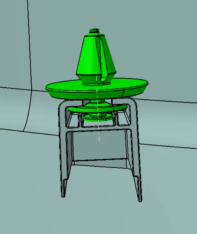
Pushpin along with the dog house is as below.
HEAT STAKES:
Heat Staking is a pulsed-heat process to join two or more parts out of which one at least is made of plastic. The process is to deform the plastic material using heat and force at a set process time. The bond is made by partially de-forming the plastic part to fix the other.
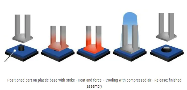
According to the design rule, a raft of 0.5 degrees is given to the heat stake and a height of 7mm should be there with the component it is to be molded.
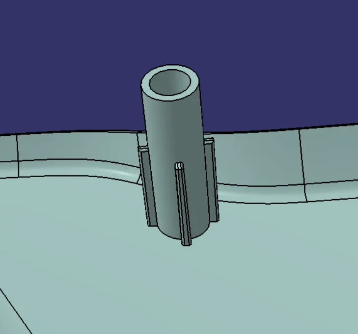
By the flange I created and the thickness given the radius of my heat stake 3mm and 2.25 mm for outer and inner.
SKETCH:
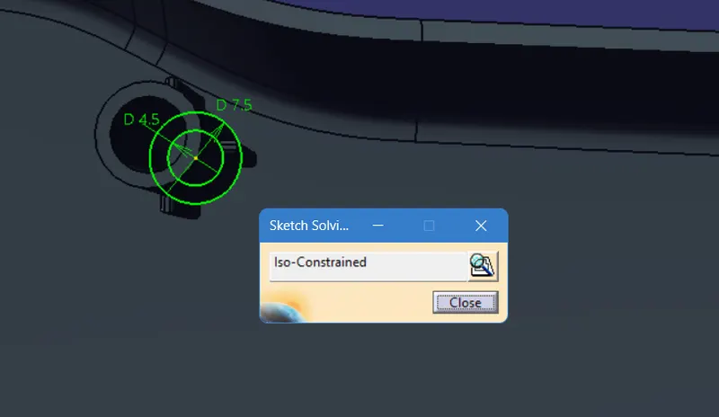
Then using pad definition solid body is created as per the master section.
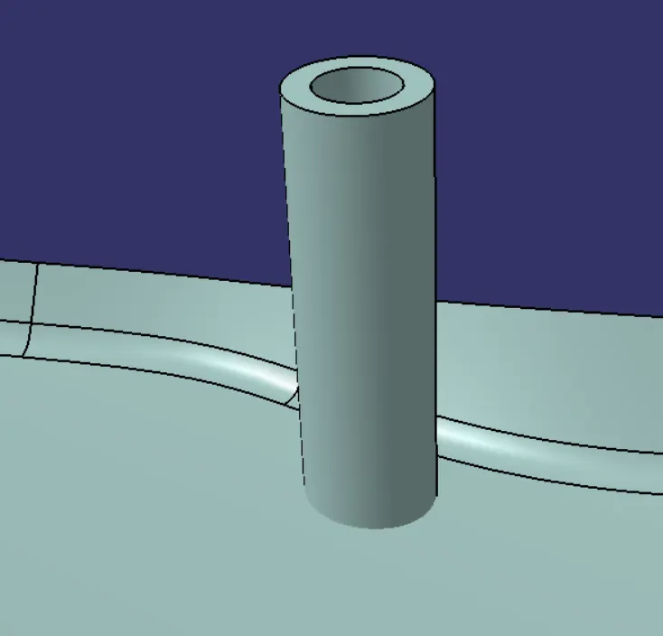
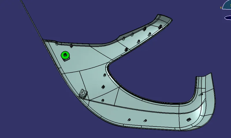
After that different points are created for heat stakes and then heat stakes are translated to that point.
After that Ribs are created to give strength to heat stakes.
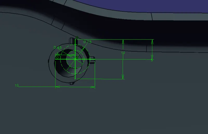
Ribs are extruded using the pad option.
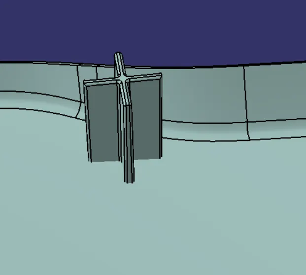
Then multiple Ribs are created and the union is trimmed to heat stakes.
Locators are created to minimize the Degree Of Freedom of the component.
Sketch:
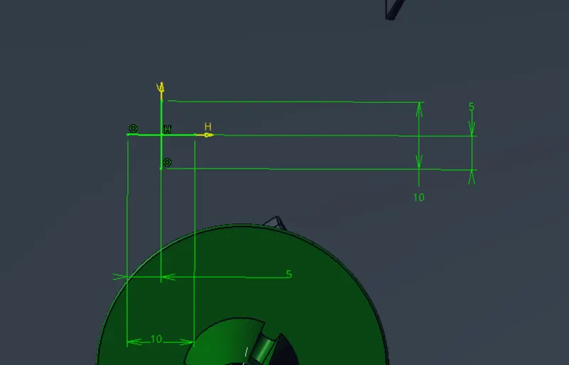
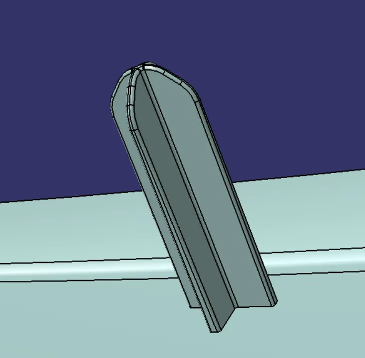
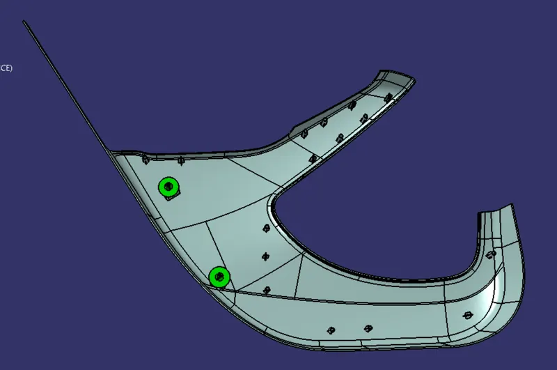
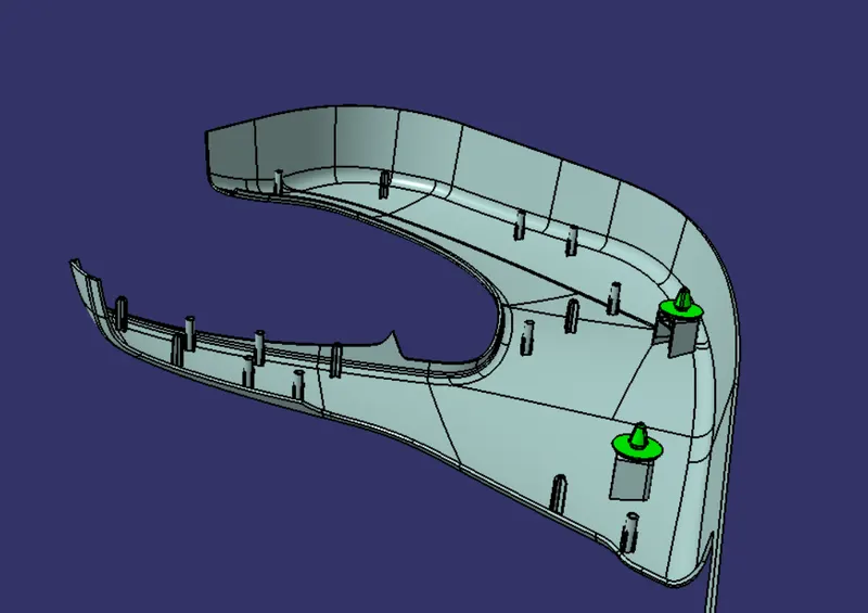
As per design guidelines, a minimum of 2 locators are required for each component so I have created 6 locators.
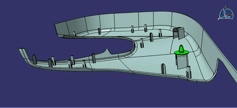
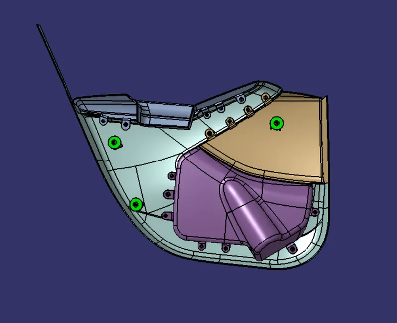
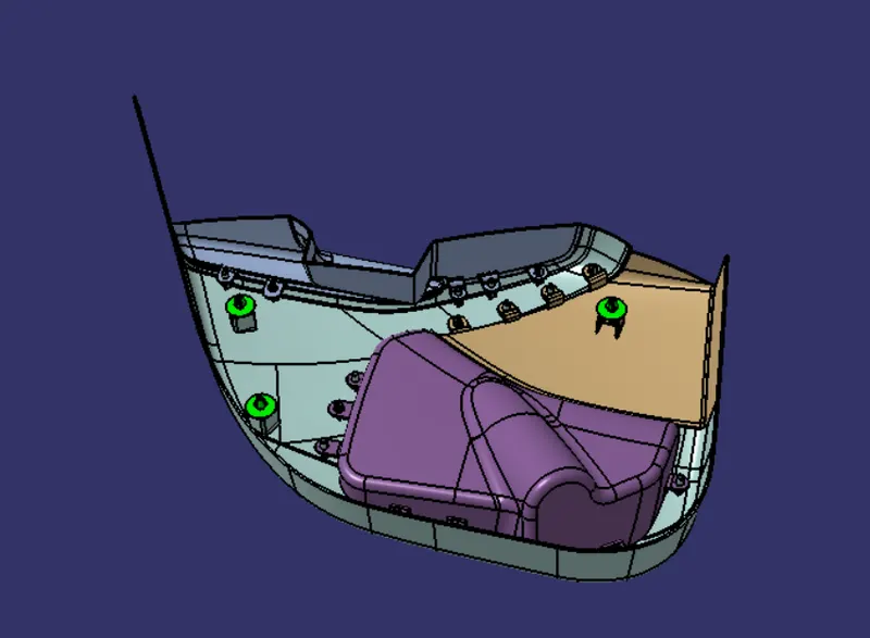
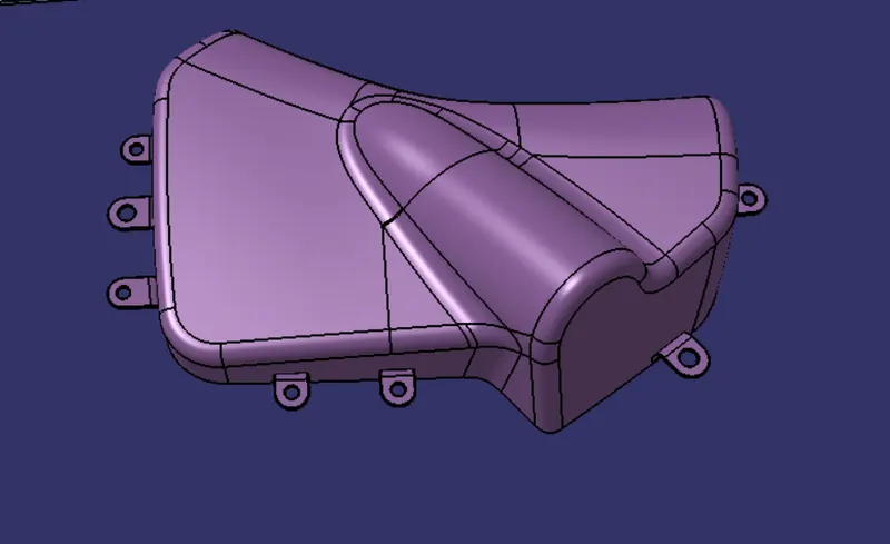
Final Output: