Week 11 - Final project
FINAL PROJECT (DOOR TRIM PANEL)
Objective: To design the part models of DOOR TRIM PANEL inside the assembly workbench from given input as Class-A Surface and then add engineering features like ribs, heat stakes, dog house etc. for part attachment.
Introduction:
Class A Surface:
In automotive design, a class A surface is any of a set of freeform surfaces of high efficiency and quality. Although, strictly, it is nothing more than saying the surfaces have curvature and tangency alignment to ideal aesthetical reflection quality, many people interpret class A surfaces to have G2 (or even G3) curvature continuity to one another.
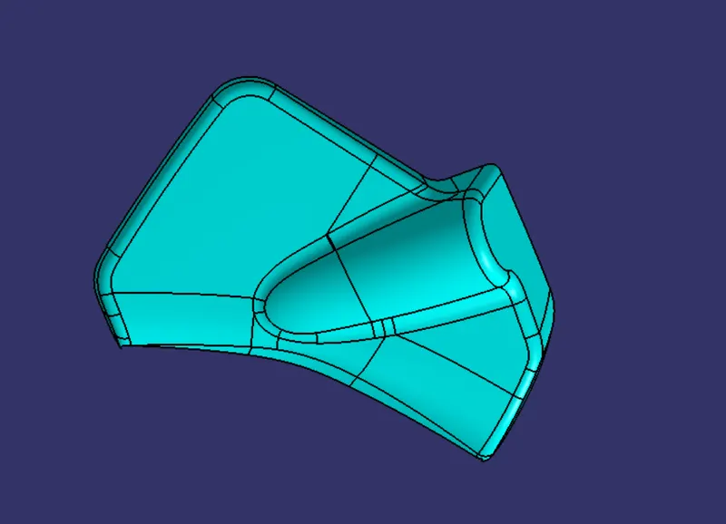
Class A surfacing is done using computer-aided industrial design applications. Class A surface modellers are also called ‘digital sculptures’ in the industry. Industrial designers develop their design styling through the A surface, the physical surface the end user can feel, touch, see etc.
In automotive industry a dedicated team is allocated to develop the Class A surface using sketches followed by ideation. A Class A surface is the first input given to the plastic designer.
Class B Surface:
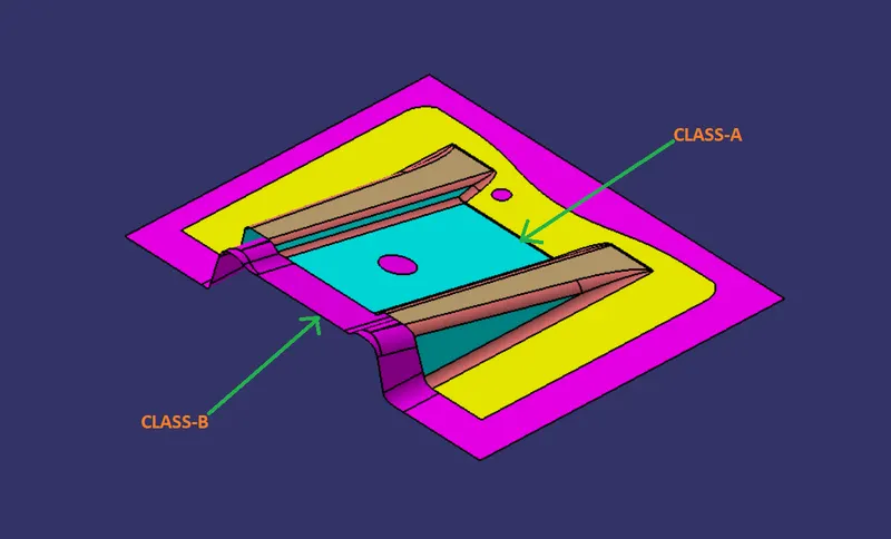
Class B Surface is a surface below a certain thickness from a Class A Surface. We can also say that it is an engineering surface because it contains all the engineering aspects of the model which is required.
Class C Surface:
Class C Surface is a surface that joins the Class A Surface with Class B Surface.
Tooling Axis:
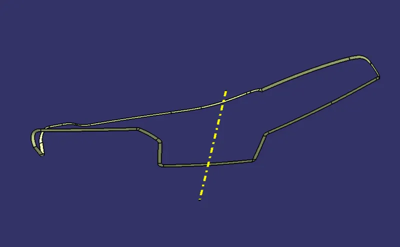
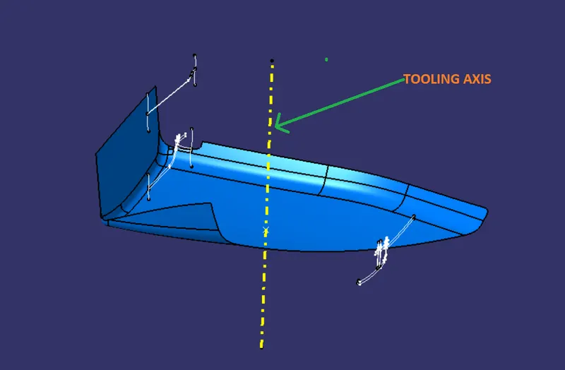
Tooling axis is the direction in which the mold or core and cavity opens.
Draft:
Draft is the angle in which the part is tapered to allow it to release. As the part cools, it tends to shrink to the core side of the mold. Draft is required on all parts in the direction of mold movement in order to allow parts to release or eject from the mold properly.
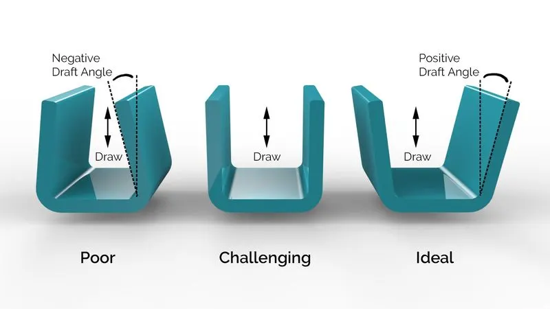
Most parts or applications require a minimum of 0.5 to 1 degree, however 3 degree is widely accepted as normal.
Draft Analysis:
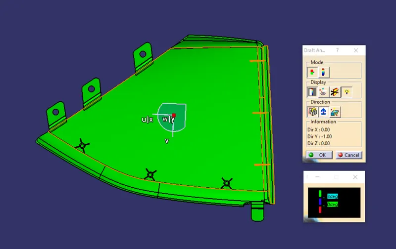
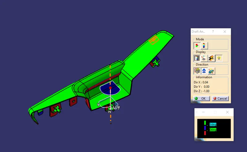
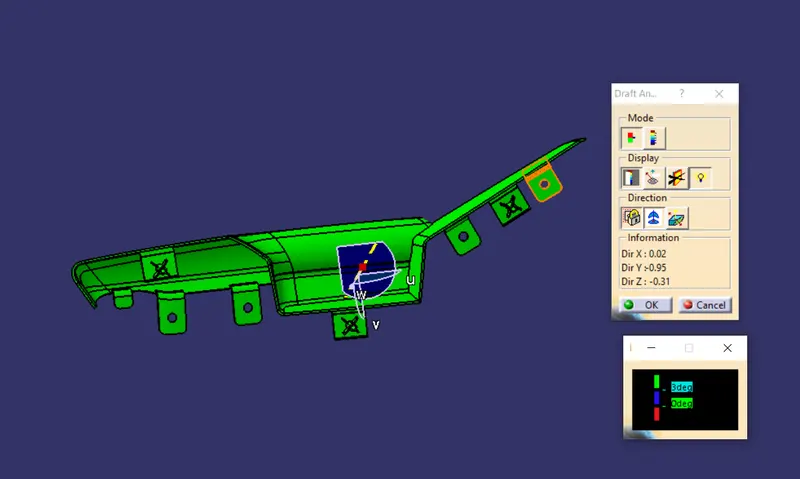
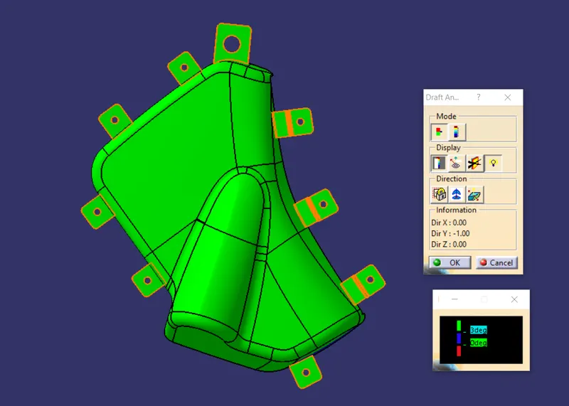
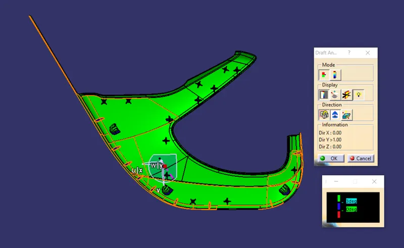
Draft analysis is done in order to detect if the part that has been drafted will be easily removed or not. This type of analysis is performed based on the colour ranges identifying zones on the analyzed elements where the deviation from the draft direction at any point corresponds to the specified values. When the draft analysis passes, it means our part is easily toolable or can be easily ejected.
Assembly modeling:
Assembly modeling is a process of creating design that consists of two or more components assembled together at their respective work positions. The components are brought together and assembled in Assembly Design workbench by applying suitable parametric assembly constraints to them. The assembly constraints allow the designer to restrict the degrees of freedom of components on their respective work positions. The assembly files in CATIA are called Product Files.
Types of Assembly Design Approach:
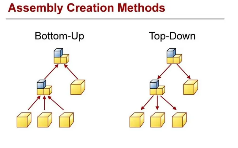
In CATIA we can create assembly models by adopting two types of approaches.
- Bottom-up Assembly
- Top-down Assembly
Bottom-up Assembly:
The bottom-up assembly is the most preferred approach for creating assembly models. In this approach, the components are created in Part Design workbench as (.CATPart) file. Then the product (.CATProduct) file is started and all the previously created components are inserted and placed in it using the tools provided in the Assembly Design workbench. After inserting each component, constraints are applied to position them properly in the 3D space with respect to other components.
Top-down Assembly:
In the top-down assembly design approach, components are created inside the Assembly Design workbench. Therefore, there is no need to create separate part files of the components. This design approach is completely different from the bottom-up design approach. Here, we have to start the product files first and then one by one create all the components. Note that even though the components are created inside the product file, they are saves as individual part files and can be opened separately later.
Procedure:
CLASS – A SURFACE OF A DOOR PANEL:
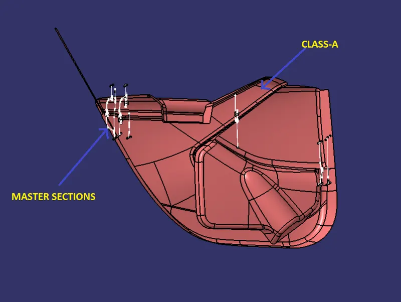
Class-A surface of a door panel is received from the styling team.
CREATION OF AN ASSEMBLY:
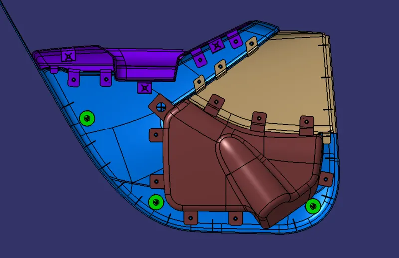
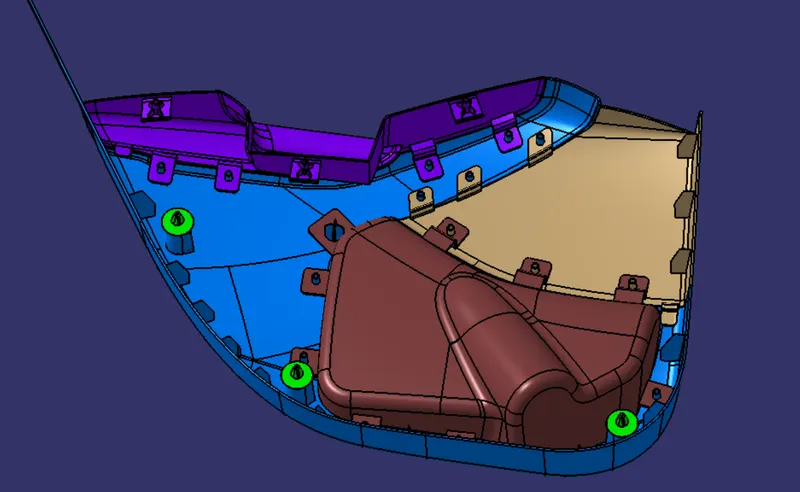
The class A of a door panel has the following parts in this project while it has also the upper substrate but we are dealing with these four components only.
- Door Arm Rest
- Map Pocket
- Bottle Holder
- Lower Substrate
1.DOOR ARM REST:
Continuity Check:
After extracting the class a surface from the input, firstly we check its continuity.
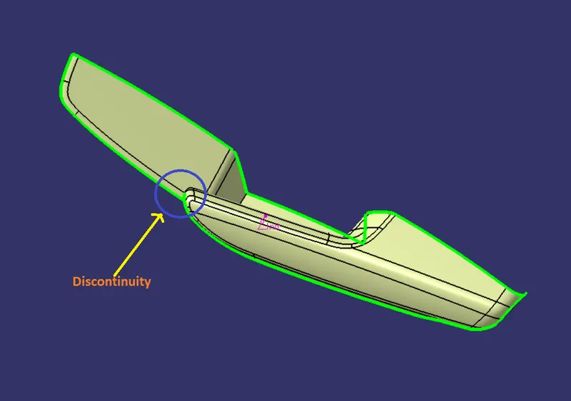
We found that there is irregularity in the surface. In this case, we have to communicate with the styling team for the improvement in the class a. But here we are proceeding with ourself and improve the class a.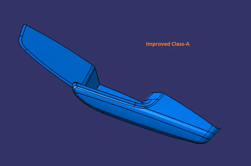
Creation of tooling axis:
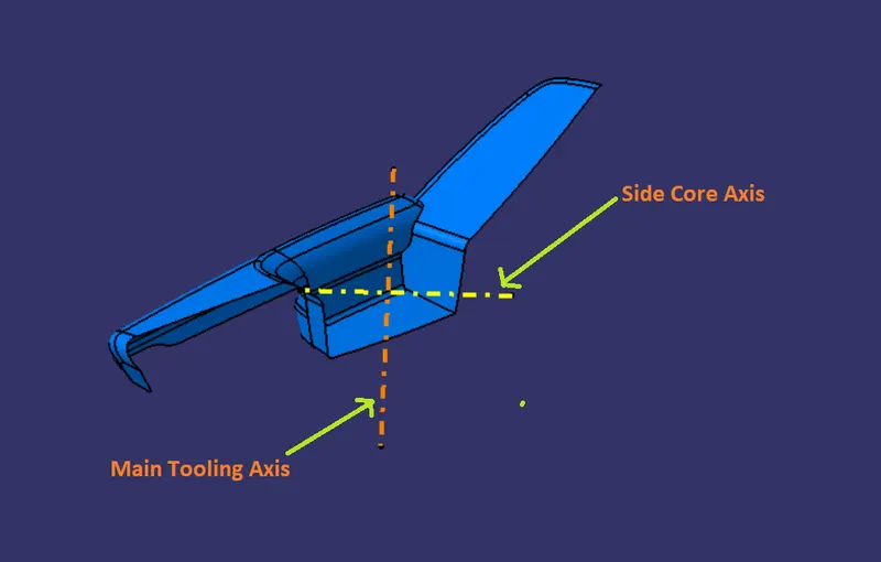
Here, an intersection is created and then using bisecting line method the main tooling axis is created.
Draft analysis of Class-A:
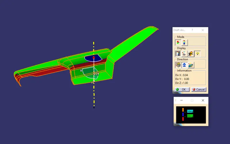
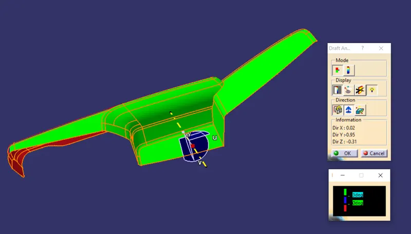
First of all, we should change the view to the Customize View parameters and then select the material mode and the ok. After that we will open draft analysis command and then click on the compass icon and then align the compass of the window with the tooling axis earlier created and then lock the draft direction. After that click on the surface and see that the surface is within permissible limit of the draft value. The surface should be green and in the column 3 degree should be inserted.
Creation of Class-B surface:
Class-B has been created by offsetting the class a surface below by 2.5 mm and extrapolating.
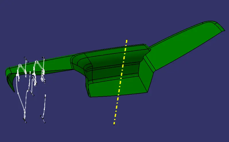
Creation of Class-C surface:
By using sweep and multi-section command the c surface were created. The angle taken in the sweep is 3 degree or 87 degree.
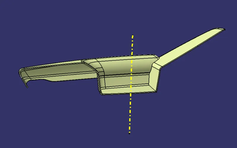
Creation of close body surface:
First of all class-a and class-c surface were joined together.
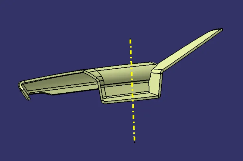
After that the join is trimmed with class b.
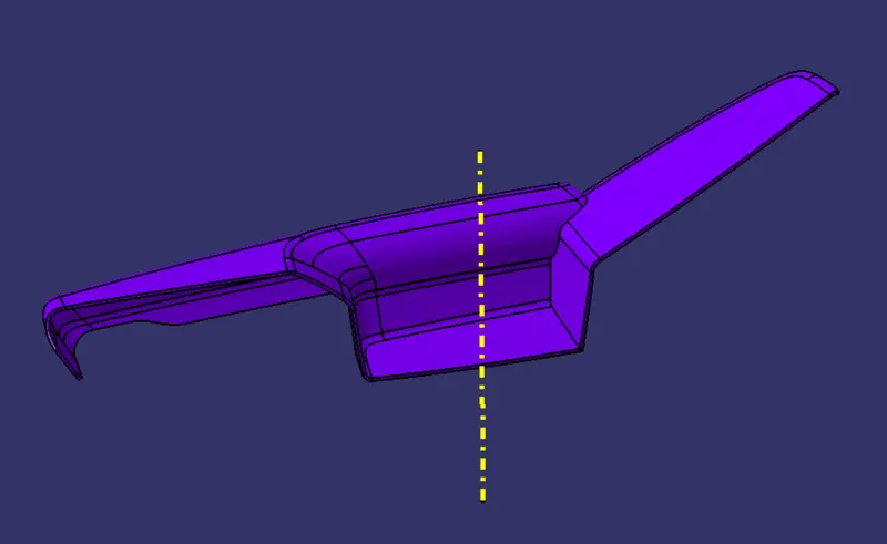
Solid body formation:
First of all, we have to go to the part workbench and then use close surface command to convert the surface into solid model.
2.MAP POCKET:
Continuity Check:
After extracting class a surface from the input data, we have to check continuity of the surface using boundary or join command.
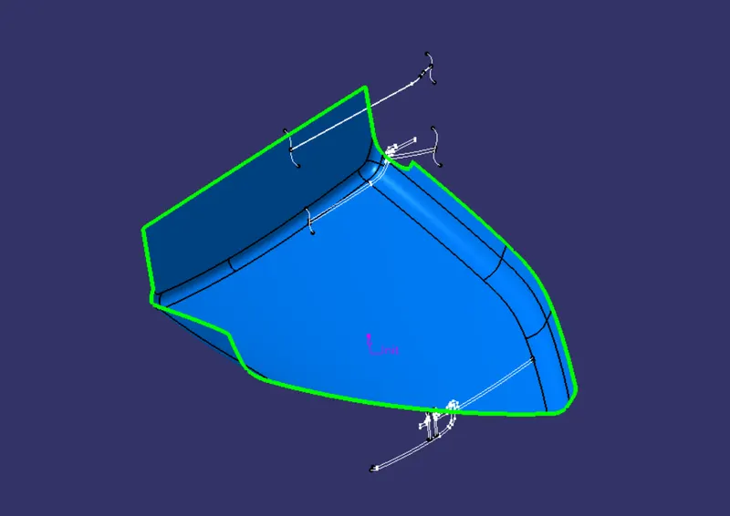
Creation of tooling axis:
After analysing the direction for tooling axis it is found that y-direction is suitable for tooling axis. So, a line is created using point and direction in y-axis.
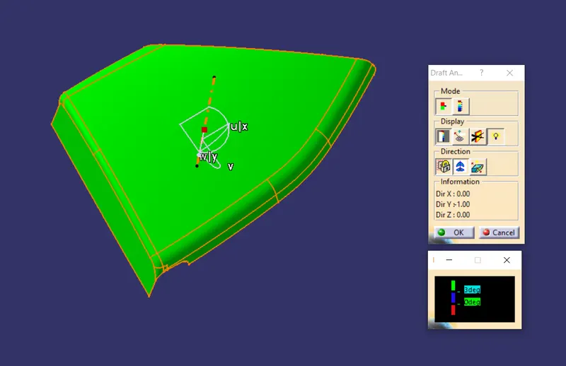
Draft analysis of Class-A:
First of all, we should change the view to the Customize View parameters and then select the material mode and the ok. After that we will open draft analysis command and then click on the compass icon and then align the compass of the window with the tooling axis earlier created and then lock the draft direction. After that click on the surface and see that the surface is within permissible limit of the draft value. The surface should be green and in the column 3 degree should be inserted.
Creation of Class-B surface:
Class-B surface is created by offsetting the class-a surface by 2.5 mm by b-side and then extrapolated.
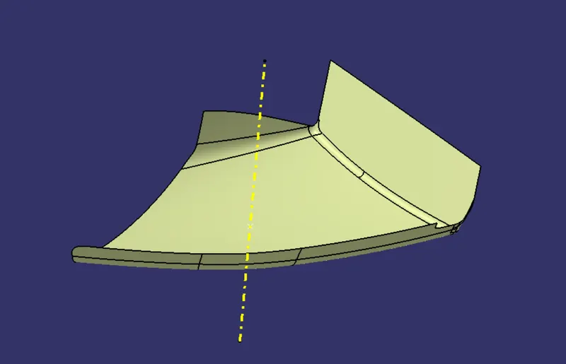
Creation of Class-c surface:
Class-C surface is created using sweep command with reference surface and multi-section solid and then joined together to get class-c surface.
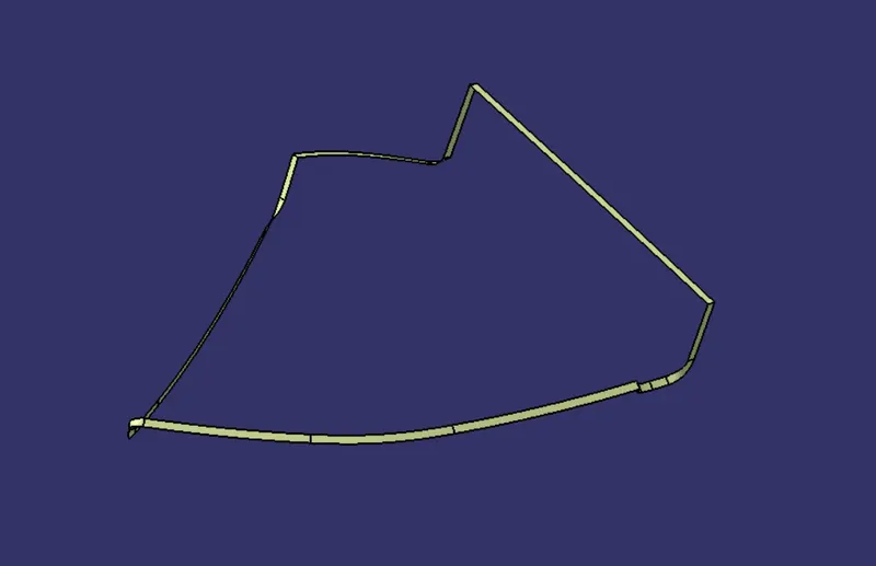
Creation of close body surface:
First of all, class-a and class-c surface were joined together.
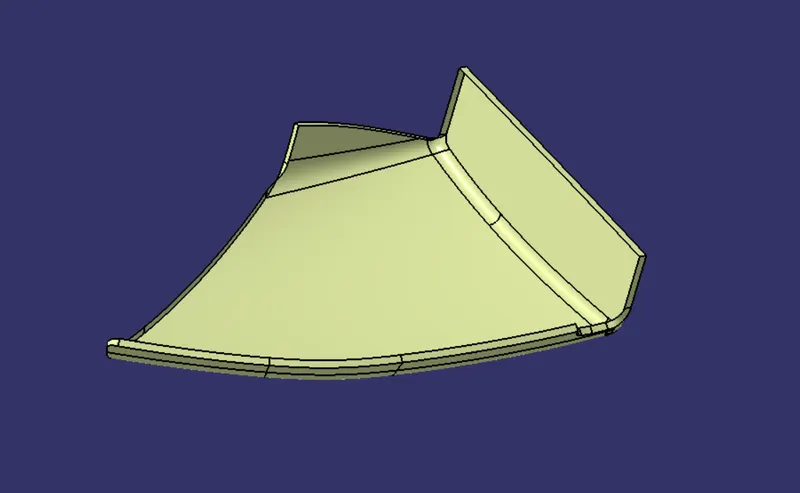
After that the join is trimmed with class b.
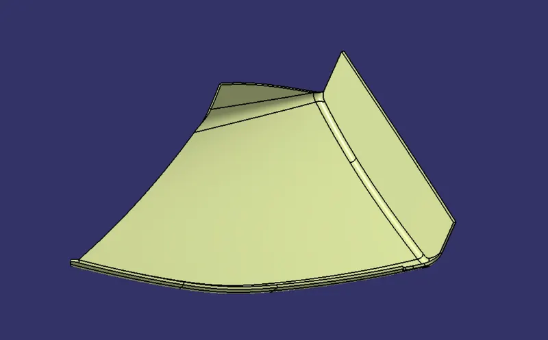
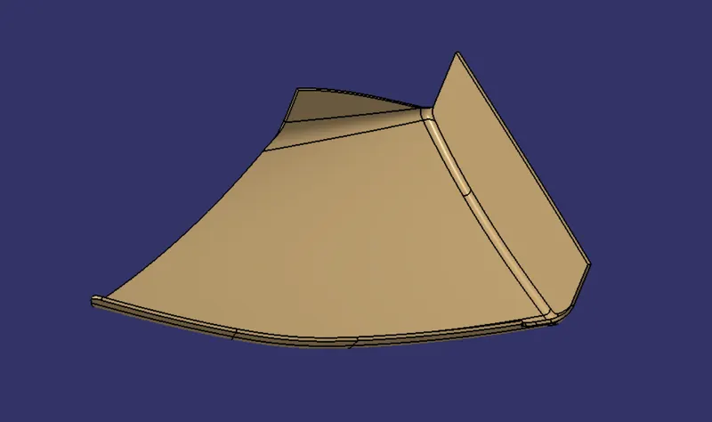
Solid body formation:
First of all, we have to go to the part workbench and then use close surface command to convert the surface into solid model.
3.Bottle Holder:
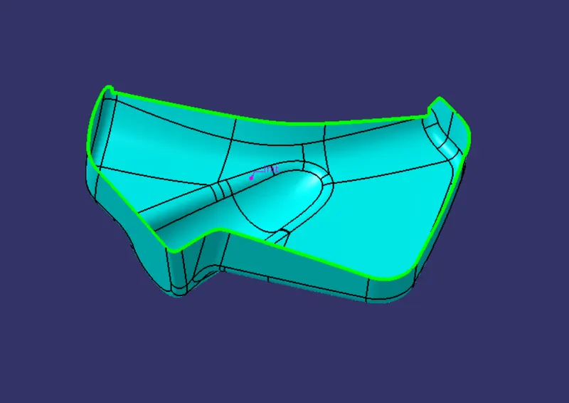
Continuity Check:
After extracting class a surface from the input data, we have to check continuity of the surface using boundary or join command.
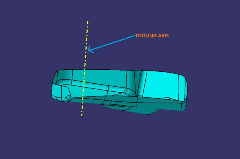
Creation of tooling axis:
After analysing the direction for tooling axis it is found that y-direction is suitable for tooling axis. So, a line is created using point and direction in y-axis.
Draft analysis of Class-A:
First of all, we should change the view to the Customize View parameters and then select the material mode and the ok. After that we will open draft analysis command and then click on the compass icon and then align the compass of the window with the tooling axis earlier created and then lock the draft direction. After that click on the surface and see that the surface is within permissible limit of the draft value. The surface should be green and in the column 3 degree should be inserted.
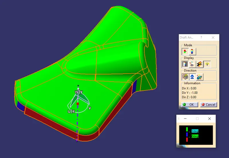
In the wall of the bottle holder, the draft is not clearing. So, we have to inform with the styling team and ask for curvature improvement.
Creation of Class-B surface:
Class-B surface is created by offsetting the class-a surface by 2.5 mm towards b-side and then extrapolated.
Creation of Class-c surface:
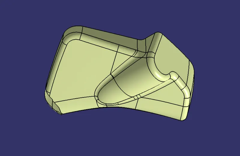
Class-C surface is created using sweep command with reference surface and multi-section solid and then joined together to get class-c surface. The angle taken to sweep is 87 degree.
Creation of close body surface:
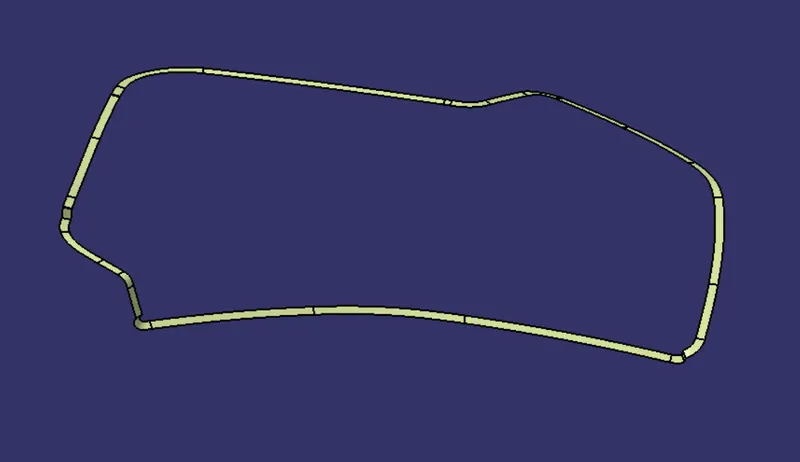
First of all, class-a and class-c surface were joined together.
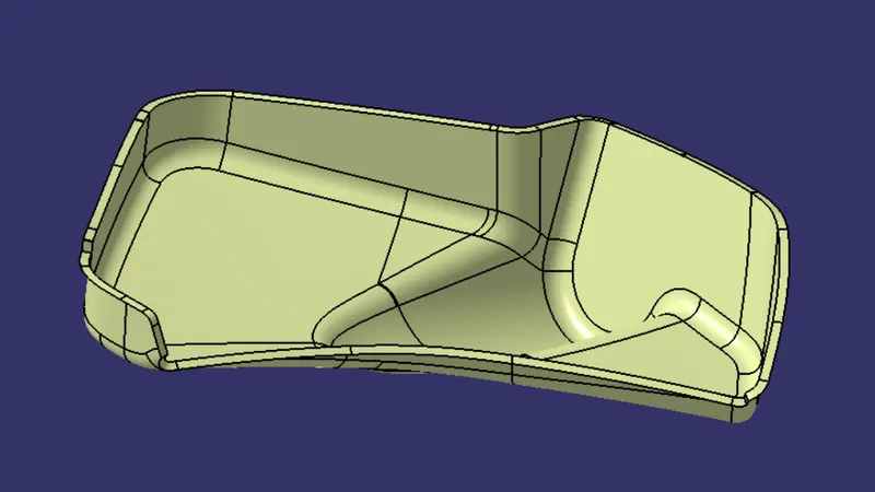
After that the join is trimmed with class b.
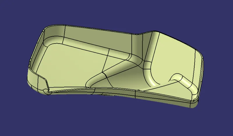
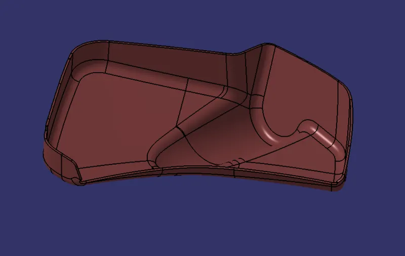
Solid body formation:
First of all we have to go to the part workbench and then use close surface command to convert the surface into solid model.
4.Lower Substrate:
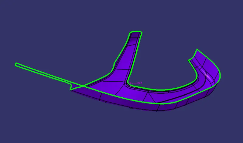
Continuity Check:
After extracting class a surface from the input data, we have to check continuity of the surface using boundary or join command.
Creation of tooling axis:
After analysing the direction for tooling axis it is found that y-direction is suitable for tooling axis. So, a line is created using point and direction in y-axis.
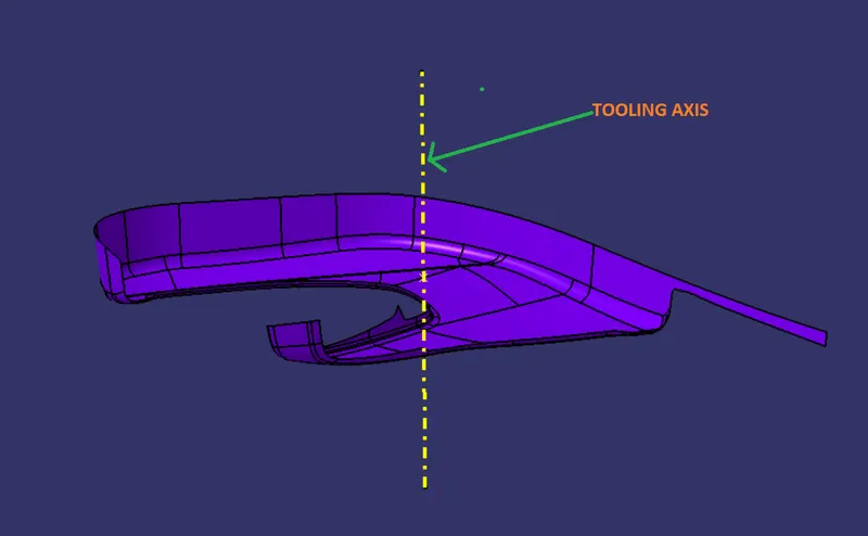
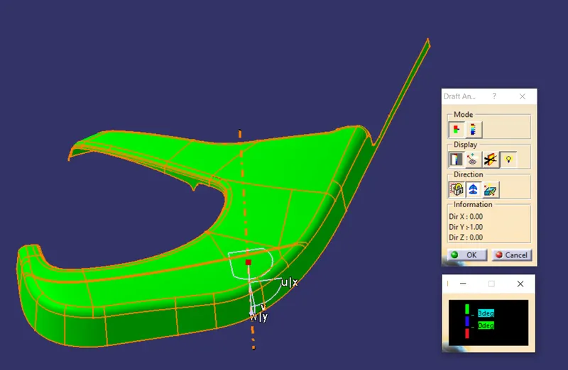
Draft analysis of Class-A Surface:
First of all, we should change the view to the Customize View parameters and then select the material mode and the ok. After that we will open draft analysis command and then click on the compass icon and then align the compass of the window with the tooling axis earlier created and then lock the draft direction. After that click on the surface and see that the surface is within permissible limit of the draft value. The surface should be green and in the column 3 degree should be inserted.
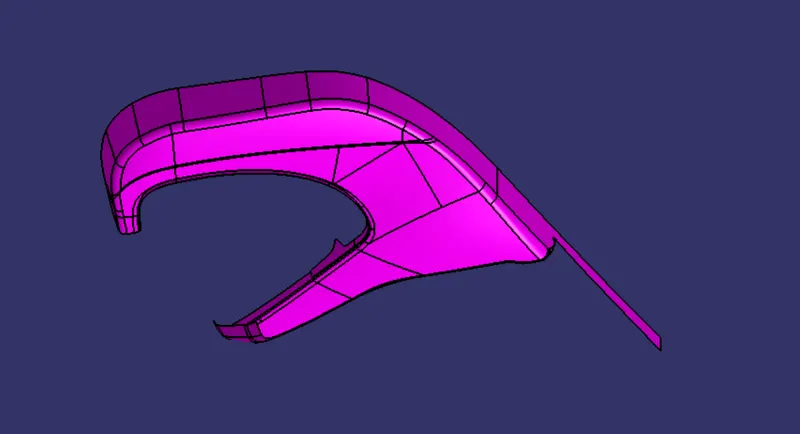
Creation of Class-B surface:
Class-B surface is created by offsetting the class-a surface by 2.5 mm towards b-side and then extrapolated. The gaps were filled using multi-section solid.
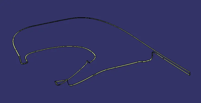
Creation of Class-c surface:
Class-C surface is created using sweep command with reference surface and multi-section solid and then joined together to get class-c surface. The angle taken to sweep is 87 degree with reference surface.
Creation of close body surface:
First of all, class-a and class-c surface were joined together.
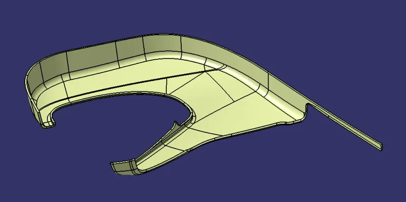
After that the join is trimmed with class b.
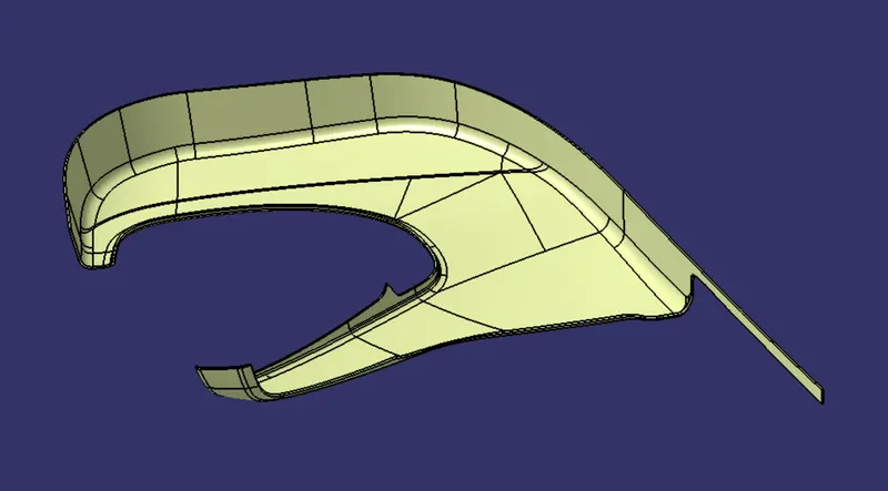
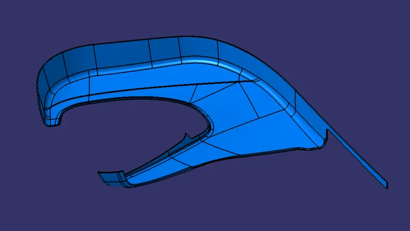
Solid body formation:
First of all we have to go to the part workbench and then use close surface command to convert the surface into solid model.
B-side Features/Engineering Features:
After completing the solid model, the engineering features were created.
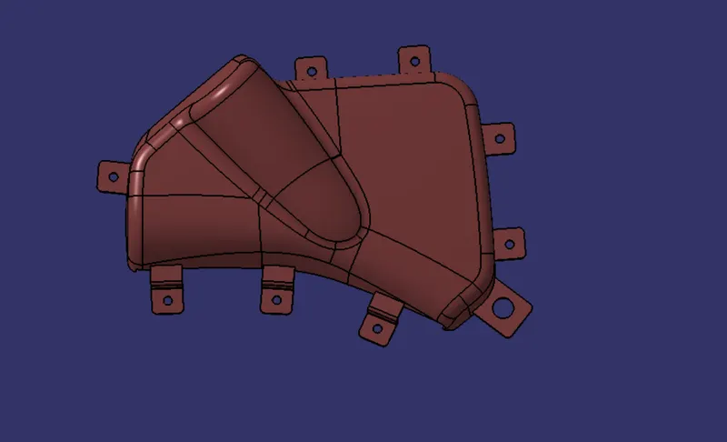
1.Flanges:
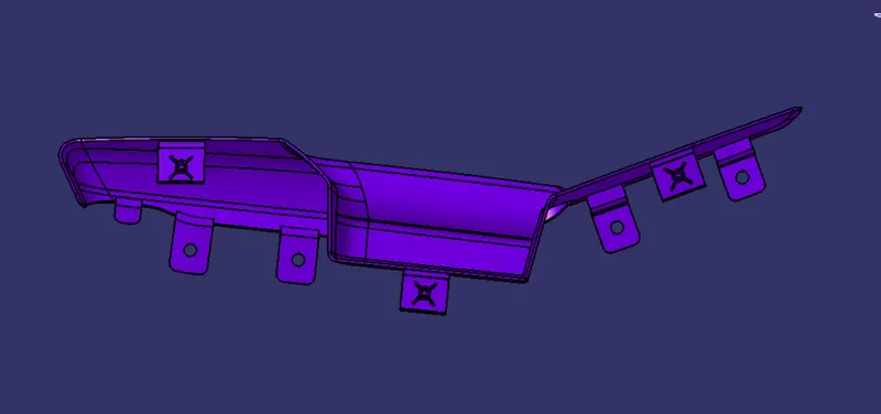
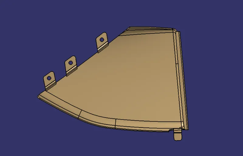
Flanges were created according to the master sections given as an input. This engineering feature has the function to hold one component to another with the help of heat stakes as heat stakes would be fitted into it. The thickness is taken as 2.5 mm from the master section. These master sections help in doing the measurements and location of the flanges. Flanges were created in the map pocket, bottle holder and door arm rest. First of all, the sketch is created and the sweep is done. Later they are converted into solid body. After that they are added to the main component.
2.Heat stakes and Ribs:
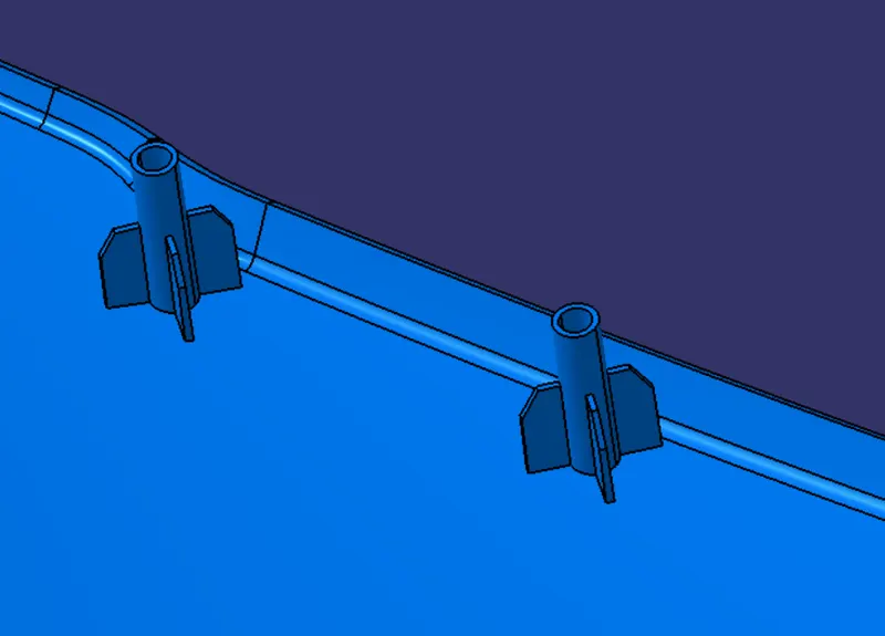
Heat staking is a pulsed heat process to join two or more parts out of which one is made of plastics. Heat stake is an engineering feature used for heat staking. They are used for accepting screws or other fastening components. Essentially, they are locating, mounting and assembly devices built into the design of the part and if not accepting screws, will attach to the mating part of another component of the design.
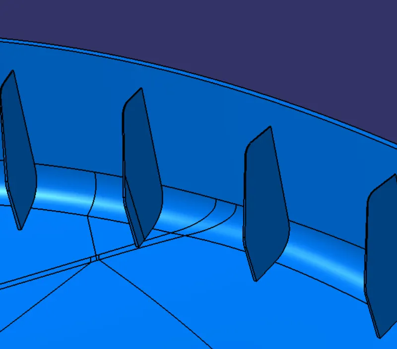
Ribs are the supporting features for providing strength. Ribs are a feature in plastic injection molded parts. They are thin extensions that run perpendicular from a wall or plane. They are commonly used to provide additional support and strength to a part. The advantage of using ribs is that they increase the strength of a part without increasing the thickness of its wall.
They also facilitate;
- Locating and arresting components of an assembly
- Providing alignment in mating parts
- Acting as stops or guides for mechanisms
General guidelines for creating ribs;
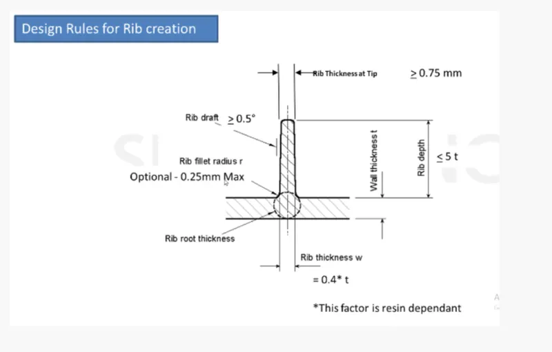
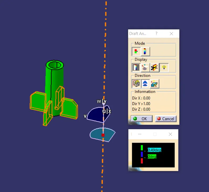
- Draft: Minimum of 0.5 degree per side which allow the rib to release from the mould.
- Rib thickness (w) should be 0.4*t (wall thickness).
- Minimum thickness at Rib Tip should be 0.75 mm.
- Rib fillet radius: Optional fillet radius (r) is maximum 0.25 mm.
- Rib height/depth should be less than or equal to 5*t (nominal wall thickness).
- Ribs should be spaced so that the steel between the ribs is at a Height / Width ratio
3:1 steel
2:1 preferred
The ratio of height/width should be less than three
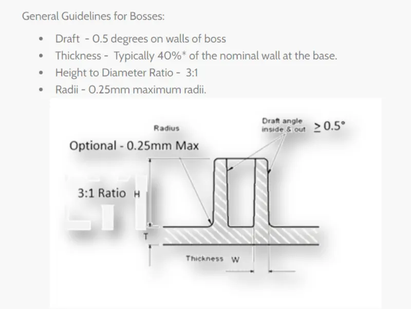
In this project heat stakes along with the ribs are provided in the lower substrate, map pocket and door arm rest. The outer diameter of heat stake is 7.5 mm and inner diameter is 4.5 mm. The dimensions have been followed using master sections provided as input. Similarly, the dimension of ribs are 20 mm x 20 mm. The draft angle provided is 0.5 degree on both ribs and heat stakes. The distance between the heat stakes is more than 60 mm. After creating ribs and heat stakes they are added to the main body.
Draft analysis:
The other type of ribs are also provided in the walls of lower substrate and map pocket in order to provide the good strength of the wall.
3.Locator:
Locator is used for locating the components before fixing it to the other components. In industry the location is going to be first and then fixation. So, the locator’s height should be at least 5 mm more than the heat stakes.
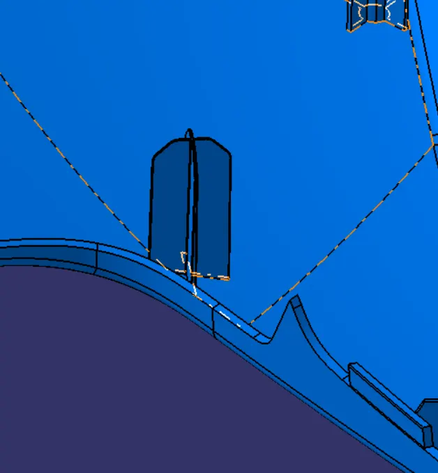
Draft analysis:
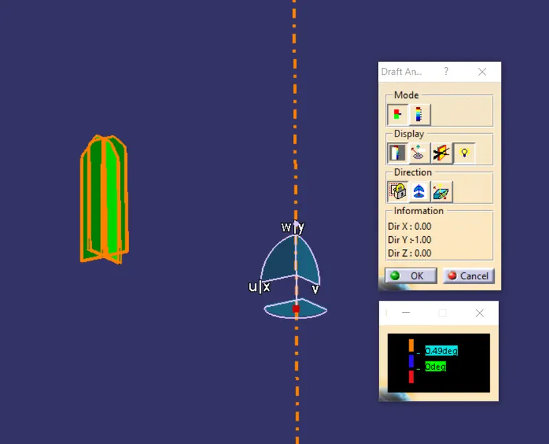
4.Counter Part Clearances:
Now we have to give clearances for each locator and heat stakes. For that, sketches should be created at the exact position of all the locators and heat stakes. After that the sketch is pad and drafted. Then all the pads are removed from the flanges. The gap between locators and the removed surface should be 0.1 mm and for the heat stakes the gap should be 0.5 mm.
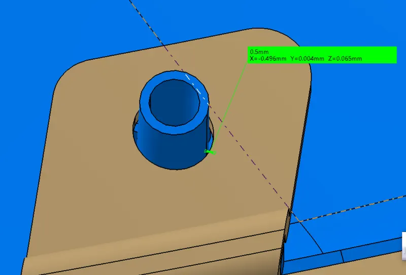
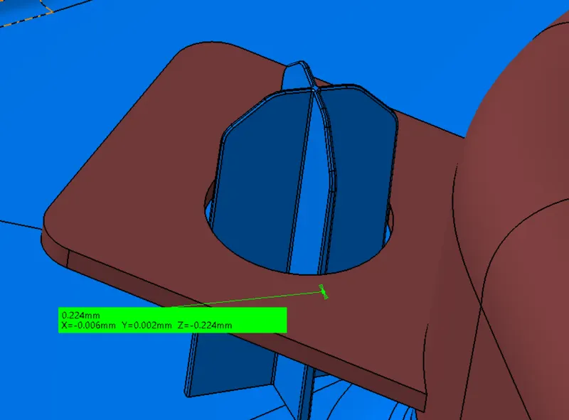
Due to the draft angle in locator, the measurement has been increased by 0.124 mm.
5.Dog House:
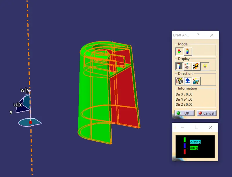
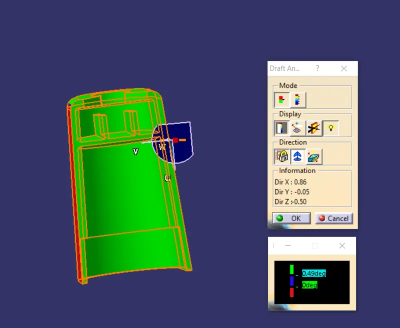
Dog house is an engineering feature used in plastic trim design. Dog houses are used as supporting features. Other engineering features like push pins, snaps, locators etc. are mounted on them to increase their strength. In this project push pins are mounted on the dog house. They are subjected to draft analysis to prevent breakage of the component during ejection from mould cavity.
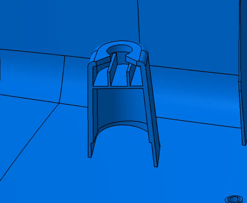
Draft analysis:
6.Push pins:
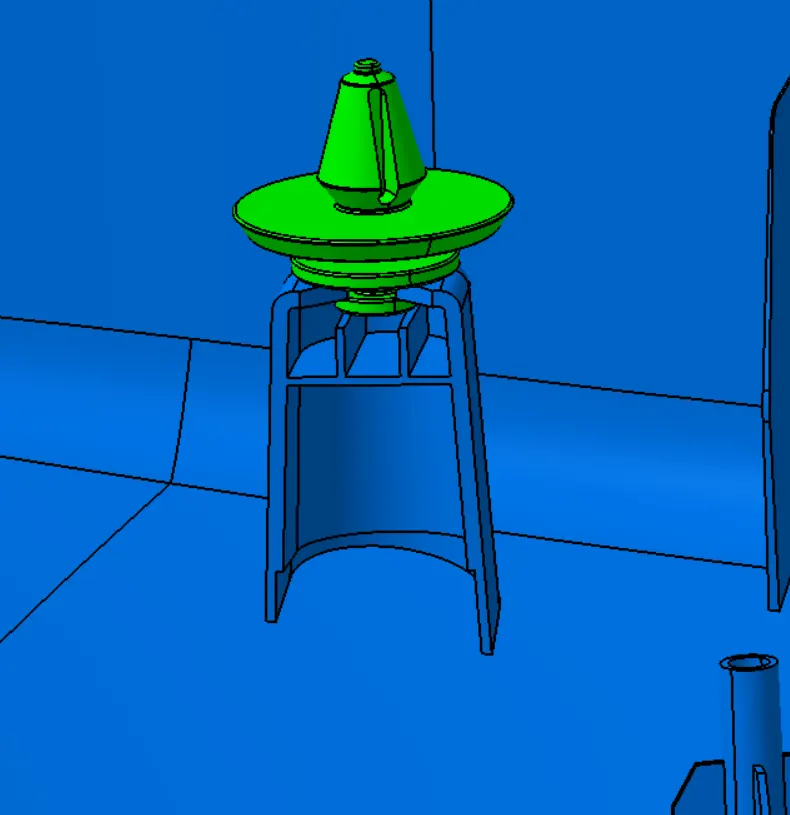
Push pins, also known as dart type fasteners, are versatile in design for a wide range of applications. When light retention is required, plastic push pins can be used hole plugs, bearing or spacers. They are well suited for simplified assembly or products knocked down for consumer assembly.
Here, push pin has been given as input so we have only assembled it with the dog house by applying assembly constraints.
Draft analysis of Final components:
Final assembly:
Applying Material:
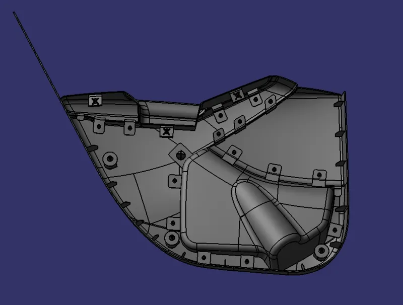
After completing the assembly of door trim panel the plastic material has been applied on the components which are shown below;
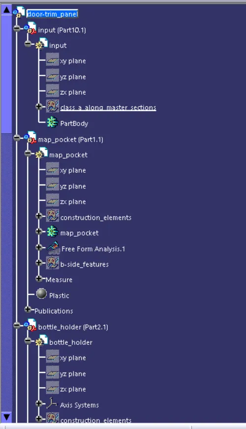
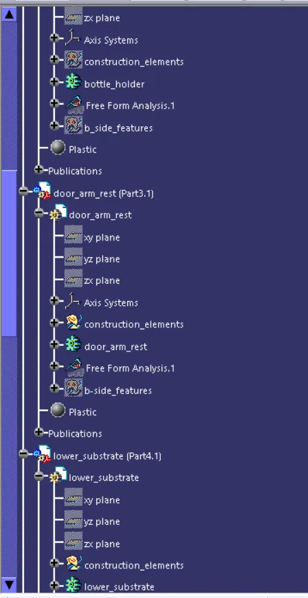
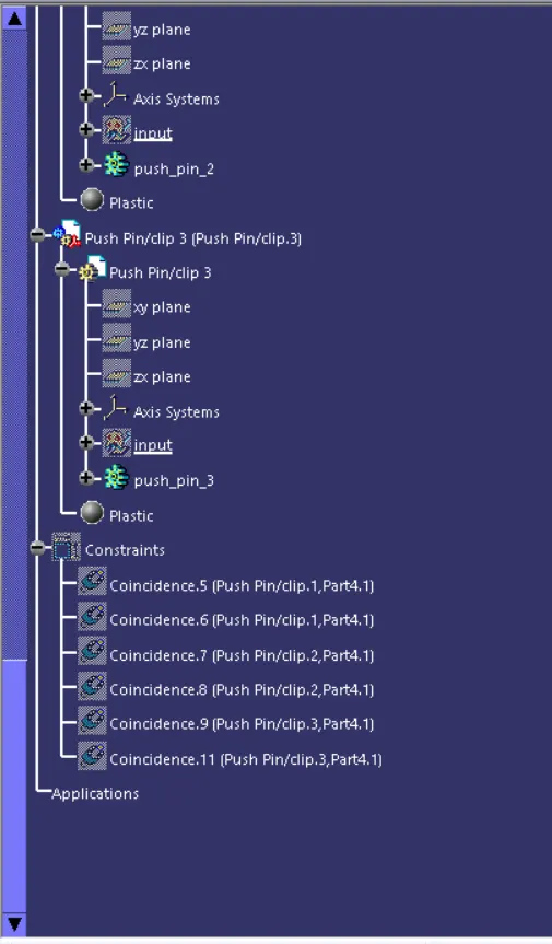
Tree Structure:

Conclusion:
From the given Class A Surface, Class B Surface and Class C Surface were created to form a solid model and Draft analysis was done for both Class A Surface and the 3d model and b-side features along with the tooling axis meeting the requirement of draft angle.