Hood design-Week 2
Title of the project: Hood Design Assembly in NX-Cad
Objective: To use the necessary design parameters to develop the hood assembly from hood outer panel, hood inner panel, hinge and striker by creating necessary embosses and reinforcement in NX Cad.
Introduction: Hood is the covering for engine in front engine vehicles, which protects the engine from sunlight and dust. Hood can open to allow access to the engine compartment, or trunk on rear-engine and some mid-engine vehicles for maintenance and repair. On front-engine cars, the hood may be hinged at either the front edge or the rear edge or in earlier models like Ford Model T it may be split into two sections on each side, each hinged along the centre line.
Functions of Hood: -
- It helps in aerodynamical flow.
- It protects the passengers and the pedestrian.
- Reduces the air resistance.
Hoods are typically made out of the same materials as the rest of the body work. They may include steel, aluminum, fiberglass or carbon fiber. However, some aftermarket companies produce replacements for steel hoods in fiberglass or carbon fiber to make the vehicle lighter.
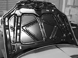
Fig.1: Hood of a car
Now for opening of hood for various purposes there is a need of hood support which will hold the hood and then one can perform his/her task in the engine.
Types of Hood support: -
There are two types of support available for the hood support.
- Gas stay
- Support Rod
1.Gas Stay:
Gas stay is a device for supporting the engine hood of a motor vehicle in its open position by means of an actuator which is activated by gas. This is mostly used when the car bonnet is heavy. In this no man power is required. Spring stays are designed to be used on upward lifting doors, once the door is opened slightly the spring will push the door to the fully open position. Euro fits stock various size springs depending on the door size requirements.
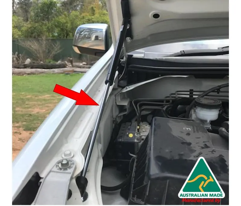
Fig.2: Gas stay
2.Support Rod:
Support rod is a device for supporting the engine hood of a motor vehicle in its open position by means of a rod. In this type we have to lift the hood by ourselves and place the support rod in the space provided either in the hood or engine component. This is mostly used where the car bonnet weight is small.
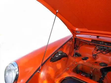
Fig.3: Support rod
Parts of Hood: -
Basically, the hood has inner panel, outer panel and reinforcement and the emboss. Latch and striker mechanism is used to open and close the hood whenever needed.
Inner Panel:
Inner panel supports the outer panel. It consists of different embosses and hole at different places. Embosses provide stiffness as well as dissipate energy towards hinges. To determine the most effective position of hole, the modal stiffness method is applied. Basically, inner panel is the offset of the parent surface (i.e. outer panel) which is considered working surface while designing it. The hinges and striker are also placed on it. The inner panel thickness is 0.75 mm.
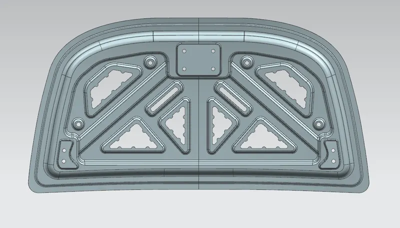
Fig.4: Hood Inner panel
Outer Panel:
Outer panel is the covering of inner panel. It is nothing but the outer skin of the inner panel. It gives the luxurious look to the hood/bonnet. Outer panel is generally the extracted model from the prototype. Outer panel and inner panel cannot be joined by any welding process like spot or rivet because it will spoil the outer look of the car. The thickness of outer panel is 0.75 mm.
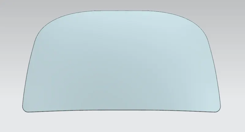
Fig.5: Hood Outer panel
Emboss:
Embossing is a stamping process for producing raised or sunken designs or relief in sheet metal. This process can be made by means of matched male and female roller dies or, by passing sheet or a strip of metal between rolls of the desired pattern.
Emboss is given due to two main reasons the first one is for pedestrian safety so that while any accidents the pedestrian should face very less injuries and damages and the second reason is during the crash the energy is dissipated outside/away from the vehicle occupants and along with the other cut outs to reduce the weight. Along with reduction in weight it even does not cost as it is a cut out. After embossing the require amount of material is trimmed and are given with fillet radius by maintaining the minimum value of 3 + 0.75 mm, so that no emboss is left out with sharp edges.
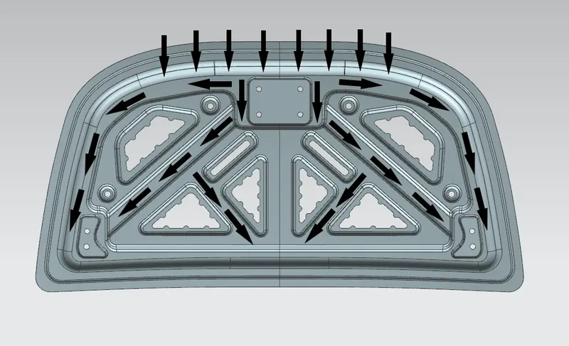
Fig.6: Emboss
Mastic sealant:
Mastic is done to join the inner panel and outer panel with 5 mm gap. It is a kind of hard rubber glue added between inner and outer panel of hood to join them at different points called mastic points locally around 80 mm diameter.
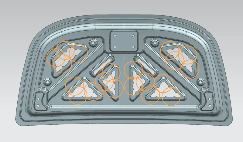
Fig.7: Mastic sealant
Design Procedure of Hood:
Data to be used:
Hood thickness information:
- Outer Panel Thickness = 0.75mm
- Inner Panel Thickness = 0.75mm
- Reinforcement Thickness = 1.5mm
Master Sketch:
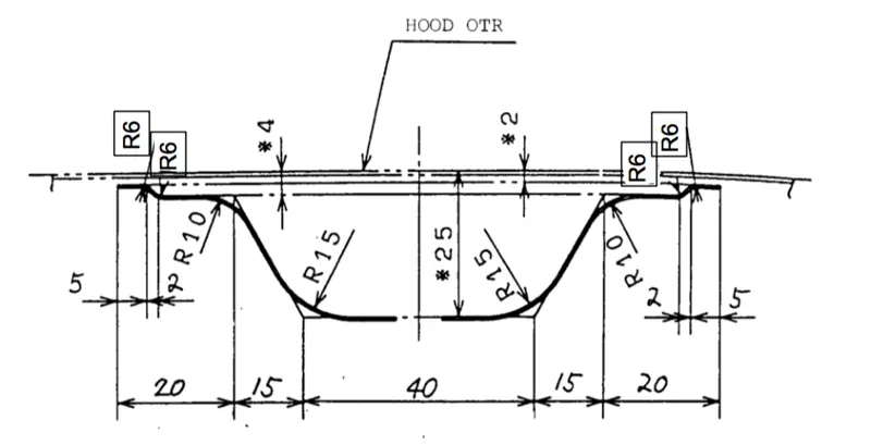
Fig.8: Master sketch
Hemming Data:
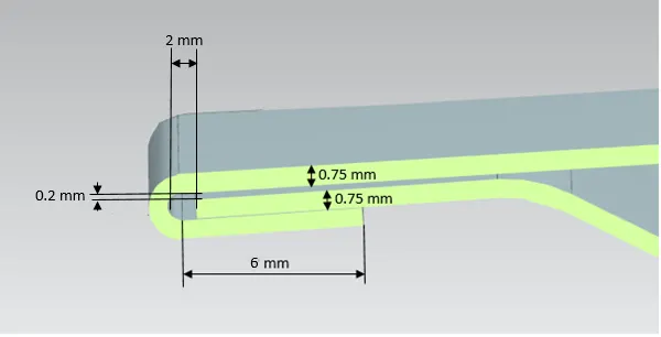
Fig.9: Hemming data
Relief rear section:
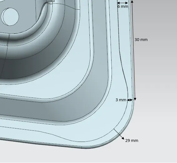
Fig.10: Rear relief section
Front relief:
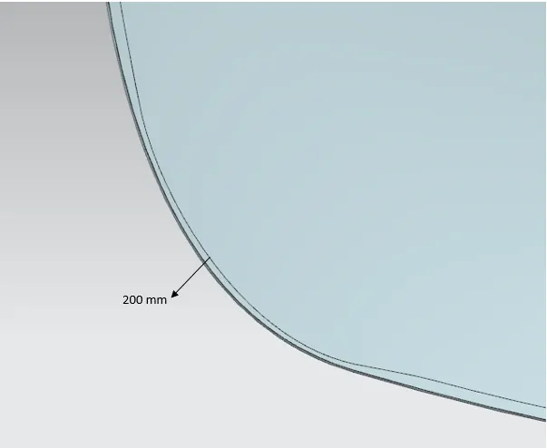
Fig.11: Front relief
- The outer panel was given by the styling department which was extracted and kept in a feature group of NX Cad. The feature group was named as parent file.
- Then in assembly navigator a new assembly was created and the parts and the sub-assemblies were added into it. Then parent body was trimmed to xc plane using the TRIM BODY command.
- The surface was offset with ‘0’ mm using OFFSET SURFACE command. After that the offset surface was kept in another feature group and named as working surface.
- According to the data given in the master section, the working surface was offset to 2 mm using command offset surface and then the curve of the edge is offset inside to 20 mm and the surface is trimmed. Similarly, the same process was followed to; OFFSET SURFACE (4 mm, 25 mm), OFFSET CURVE IN SURFACE (22 mm, 50 mm), TRIM SHEET, THROUGH CURVES and FACE BLENDS (6 mm, 10 mm and 15 mm).
- Now, the curve was projected to the inner panel and the embosses of different shapes was created using emboss command and law extension command. The draft angle was given 10 degrees on the side of punching.
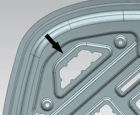
Fig.12: Embossing
- To create these faces EMBOSS, LAW EXTENSION and TRIM and EXTEND commands were used. After that FACE BLEND and EDGE BLEND commands are used to give fillets to these shapes.
Euro NCAP standards followed while creating emboss:
The hood should be designed in such a way that the passengers sitting inside the car will be safe and at the same time the pedestrian safety should also be taken. Due to this the standards and quality of the car is improved. So, whenever a car hits a Pedestrian it should cause minimum damage or injuries to him/her. For this, the material should be removed from the inner panel at specific portions.
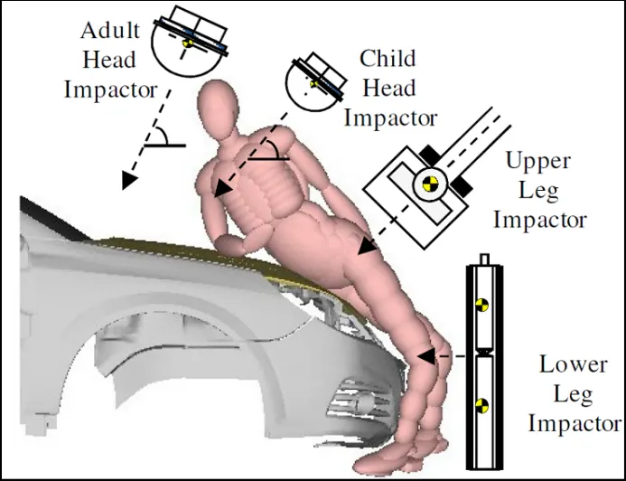
Fig.13: Pedestrian head impact zone
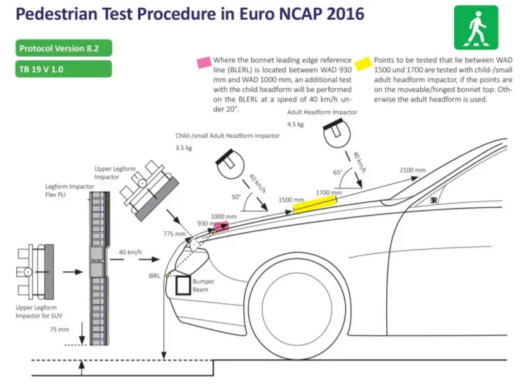
Fig.14: Euro NCAP standard 2016
WAD (Wrap Around Distance): The distance on which the head impacts on the car from the ground is called as the Wrap Around Distance. The wrap around distance is measured longitudinally in the centre of the vehicle from the ground. During the crash analysis, based on Wrap Around Distance (WAD), two test areas will be created namely Child head impact zone and Adult head impact zone. The Child head impact zone is between 1000 to 1700 mm WAD and the adult head impact zone is between 1700 to 2100 mm WAD.
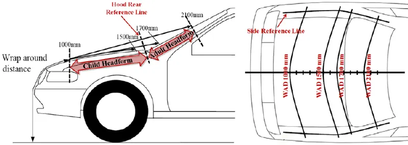
Fig.15: Wrap Around distance
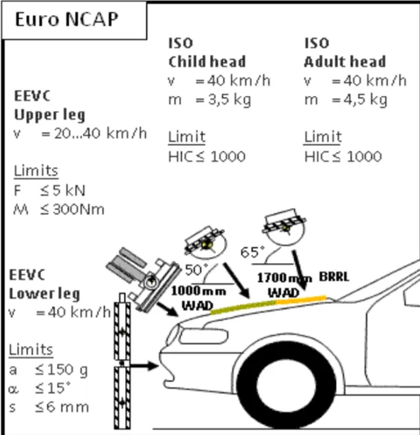
Fig.16: WAD standards and limits
The embosses are designed on the inner panel to reduce the material from the areas where the child head impact zone and adult head impact zone lie. The material is removed from these areas to make it weak so that during collision there should be minimum impact to the pedestrian.
- After that the sheet is mirrored to xc plane using MIRROR GEOMETRY command.
Fig.17: Mirrored inner panel
- Once the part was mirrored it was checked for any intersection or hole left by using EXAMINE GEOMETRY command and the sheet was extended using EXTEND SHEET command and then extra sheet was trimmed using TRIM SHEET command along ZC plane.
- Then the sheet was again mirrored and sewed to combine the mirrored sheet using SEW command.
- Mastic Sealant was created in order to join the inner panel with the outer panel.
Fig.18: Mastic points
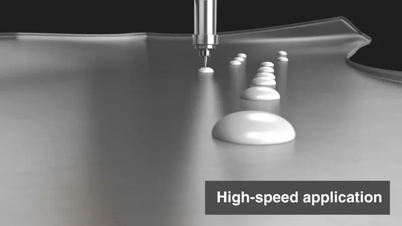
Fig.19: Adding mastic points
- After that Hinge was placed on the hinge emboss and then mirrored in the zc plane. Two points are created on the both hinges and a line is drawn which passed through the both points and the hinge axis.
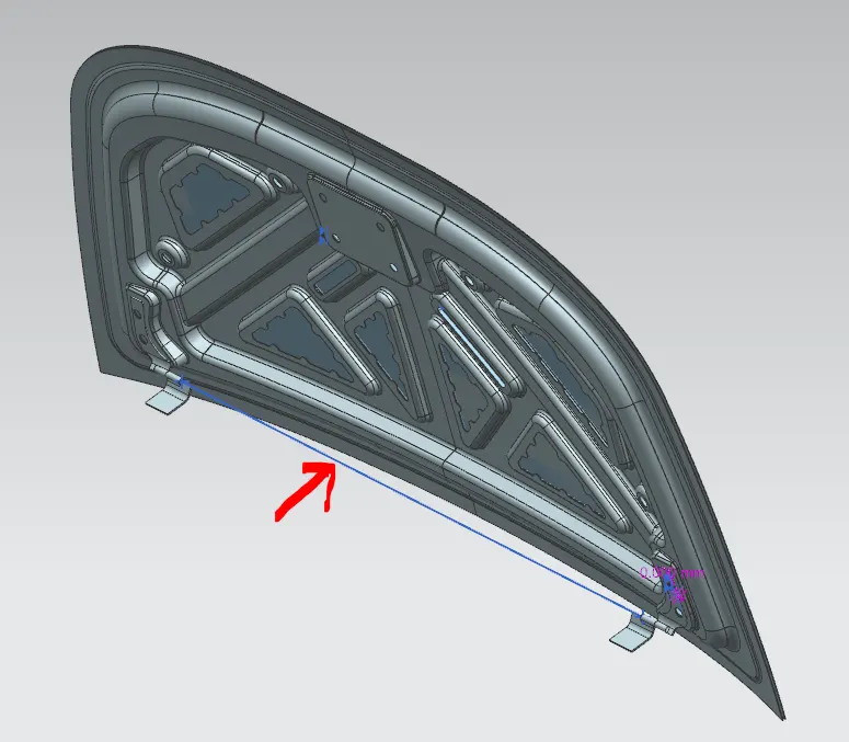
Fig.20: Hinge axis
- In order to place the striker the big circle is created at the middle of the geometry and a tangent line is drawn on the circle for the correct placement of the striker. It was positioned tangent so that perpendicular to be obtained. The striker is then placed on its embossed position.
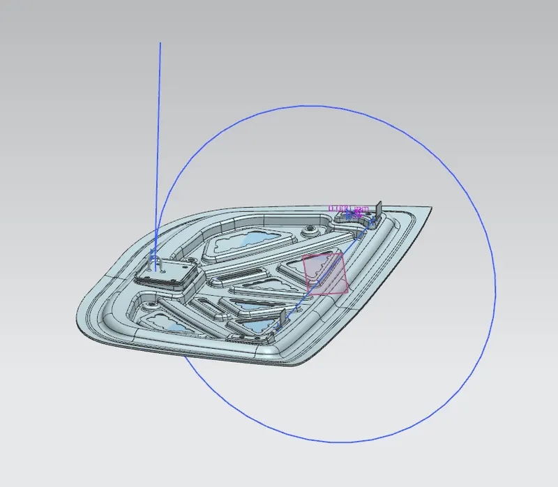
Fig.21: Striker positioning
- After that the outer panel was offset to 0 mm and curve on surface of 0.5 mm from outer edge was created inside for law extension. Then the law extension was offset to 15 mm inside which is the effective hemming length and the face blend is done on the three face. Then the inner panel was trimmed 2 mm from outside edge and then thickened up to 0.75 mm. The hemming was then created.
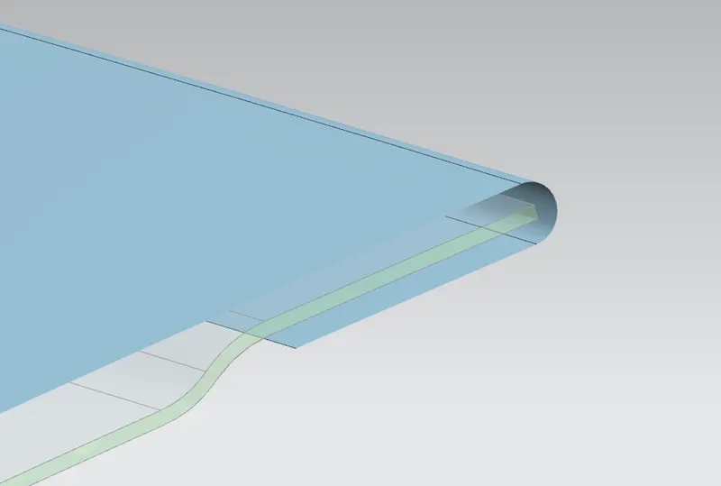
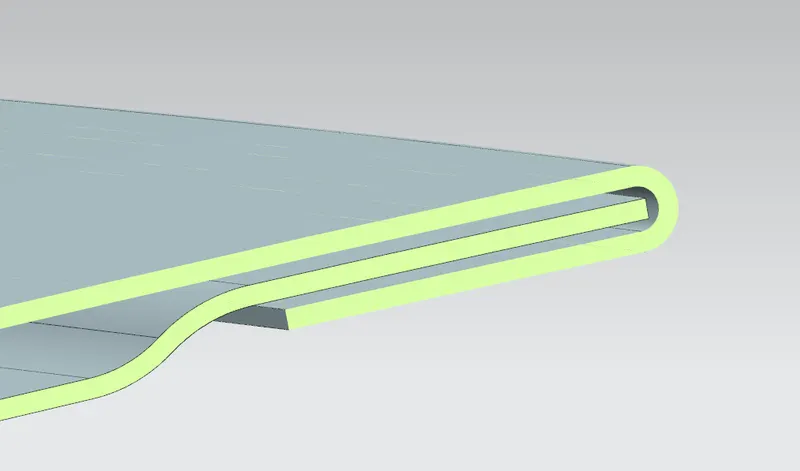
Fig.22: Hemming flange before and after thickening
- After that the rear relief and front relief was created by using commands like PROJECT CURVE, TRIM SHEET and the outer panel is thickened up to 0.75 mm.
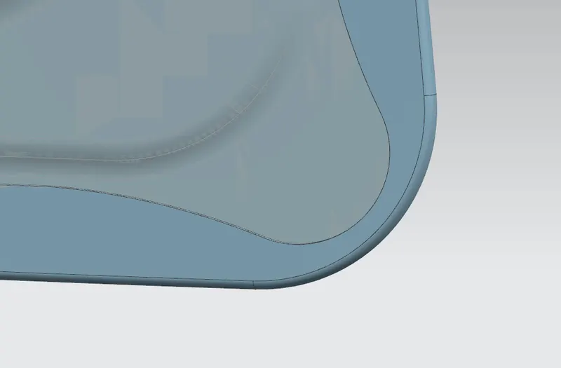
Fig.23: Rear relief section
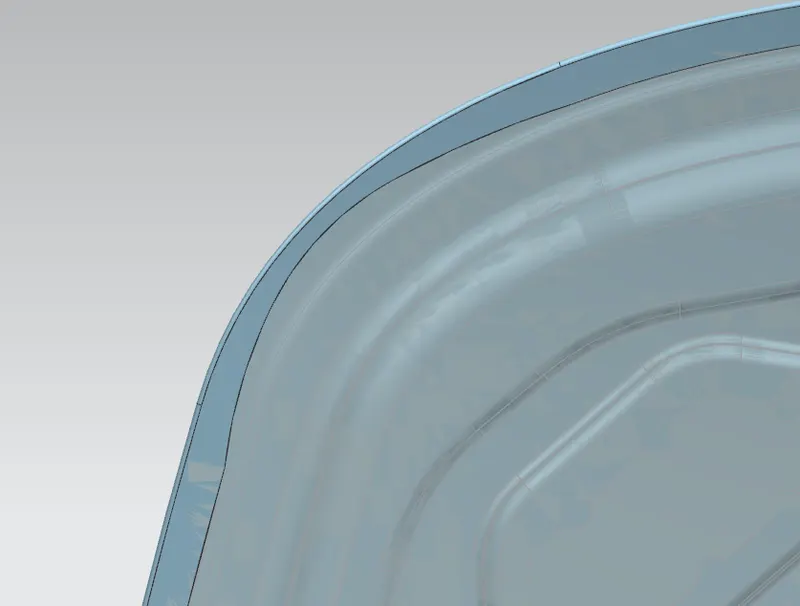
Fig.24: Front relief
15. Then the hood assembly is finally created.
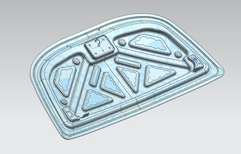
Fig.25: Hood assembly
At last both the inner panel and the outer panel was extracted, copied and kept in separate part files.
Manufacturing Methods to be used in the design:
- Deep Drawing: Deep drawing is a process of converting the sheet metal into cylindrical or box shaped structure with or without changing its length or thickness. Many cylindrical parts like metal can, pots, container, automobile fuel tanks etc are deep drawing products.
Parts used in deep drawing process:
- Circular Die
- Blank holder
- Punch
- Blank
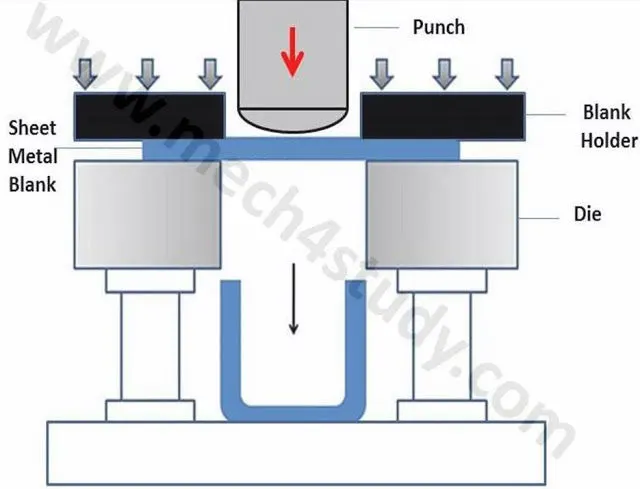
Fig.26: Deep drawing
- Hemming: Hemming is a forming operation in which the edges of the sheet are folded or folded over another part in order to achieve a tight fit. Normally hemming operations are used to connect parts together to improve the appearance of a part and to reinforce part edges.
Types of hemming operation:
- Conventional die hemming
- Roll hemming
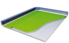
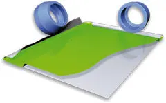
Fig.27(a): Conventional die hemming fig.27(b): Roll hemming
Conclusion: Thus the hood inner pannel is created and the assembly of hood outer panel, inner panel, hinge and striker are done in NX Cad using the commands like emboss, law extension, face blend, edge blend, offset curve on face, offset surface, thicken, mirror geometry, trim sheet, trim and extend etc. and gain good knowledge about them.