Photo Realistic Rendering
Title of the Project: American Copper Bike
Objective:
To learn SolidWorks by modeling the different parts of the American Chopper Bike and its assembly using different tools like line, circle, spline, extrude, revolve, mirror, fillet etc.
Introduction:
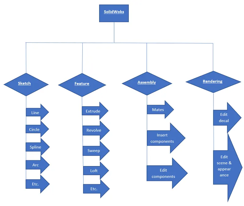
SolidWorks is a professional software used by design engineers in order to create 2D sketch, 3D models, surface models, assembly of the different parts, rendering and many more. It is also helpful to apply different appearances to our models. In this software firstly a 2d sketch is created and the converted that sketch into 3d model and surfacing. After the parts are created then they are assembled together to make them a product. Then we have different other things to do like rendering and different other things according to the necessity.
American Chopper Bike is one of the most popular bike started in 2003. It focuses on Paul Teutul Sr, his son Paul Teutul Jr and their company, Orange County Choppers which is located in Orange County, New York. This Chopper is very interesting because of the differences between the vision and styles between the father and son. They focus on restorations and customizations of choppers built in the US.
Design methodology/approach:
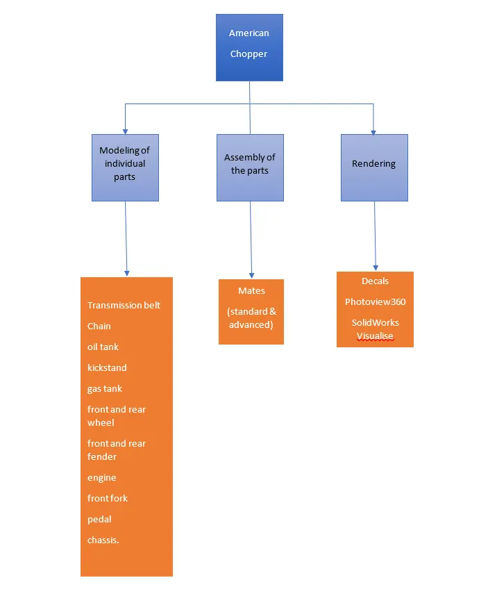
Components of American Chopper:
- Transmission Belt
- Kickstand
- Front Fender
- Rear Fender
- Chain
- Oil Tank
- Pedal
- Front Wheel
- Rear Wheel
- Front Fork
- Chassis
- Engine
- Gas tank
1. Transmission belt:
A belt is a mechanical elements which is used to transmit power without phase shift. Belts are made up of flexible materials used to mechanically connect rotating shafts, generally parallel. Belts can be used as transmission elements, source of motion or to efficiently transmit power.
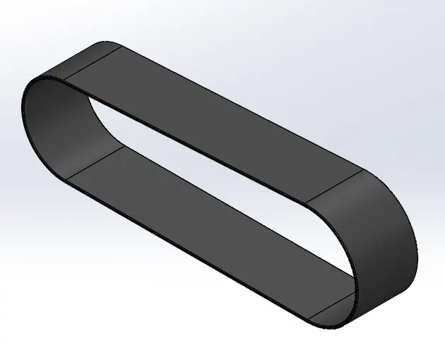
Command used:
- Line
- arc
- trim
- extrude
- fillets
Line: It is used to draw a line in horizontal, vertical or to a specific angle.
Arc: It is a part of a circle which has a starting and a ending points with a define radius.
Trim: It is used to remove a part of our object from nearest intersecting points.
Extrude: It is used to add a material to our object I a normal direction.
Fillet: It is used to create a round corner at a defined radius.
2. Kickstand:
It supports the Motorcycle when it is perked so that it doesn’t tip over. It is a piece of metal that flips down from the frame and makes contact with the ground.
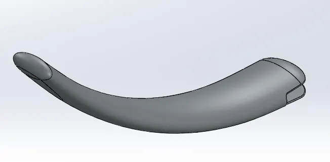
Commands used:
- Ellipse
- circle
- spline
- line
- loft
- extrude
- dome
- fillet
Ellipse: It is used to create a circular oval shape by defining two radius (i.e. major radius and minor radius)
Circle: It is used to create a circular shape by defining a point and a radius.
Spline: It is a curvy line which is used to create curve lines based on its points.
Loft: It is used to add a material according to our profiles at a certain distance.
3. Front Fender:
It is a part of an automobile, motorcycle or other vehicle that frames a front wheel in a very good way.
The primary purpose is to prevent sand, mud, liquid and other particles which is thrown in the air by the by the rotating tire.
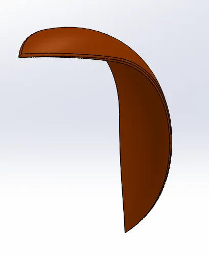
Commands used:
- Arc
- spline
- construction line
- revolve
- split
- fillet
Construction Line: It a part of a line having same properties but it acts as a reference to a certain geometry.
Revolve: It is used to add a material by rotating around a reference axis according to its shape and defined angle.
Split: It is used to cut our part in reference to a line and selected parts.
4. Rear Fender:
It is a part of an automobile, motorcycle or other vehicle that frames a rear wheel in a very good way.
The primary purpose is to prevent sand, mud, liquid and other particles which is thrown in the air by the by the rotating tire.
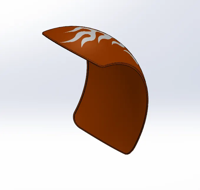
Commands used:
- Arc
- spline
- construction line
- revolve
- split
- fillet
Construction Line: It a part of a line having same properties but it acts as a reference to a certain geometry.
Revolve: It is used to add a material by rotating around a reference axis according to its shape and defined angle.
Split: It is used to cut our part in reference to a line and selected parts.
5. Chain:
In Motorcycle chain is used to connect the output shaft of the transmission to the rear wheel. It makes the rear wheel rotate which moves the motorcycle.
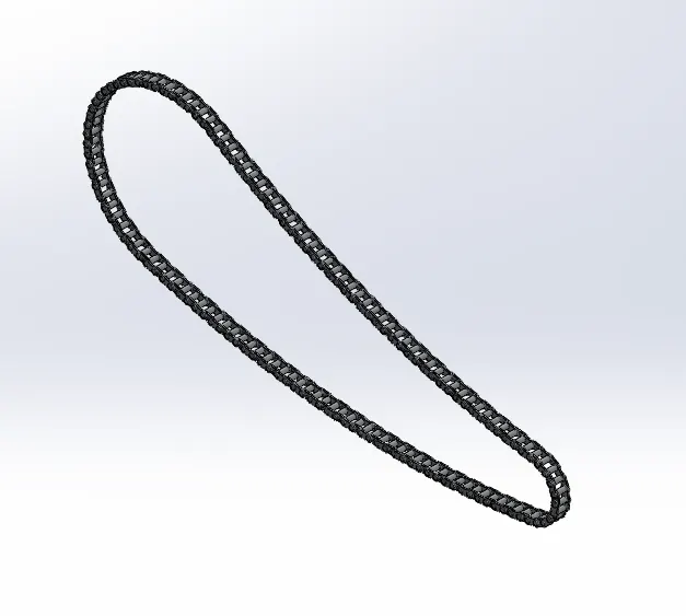
Commands used:
- Arc
- circle
- center point straight slot
- extrude
- fillet
- circular pattern
- mirror
Center point straight Slot: It is used to create a slot like geometry by giving a mid-point reference line then provide slot radius.
Circular pattern: It helps to pattern our objects in a circular form according to a reference circle by providing entities and total angle or between angle.
Mirror: It helps to create a copy image of an object in reference to a line/face/plane but the copy image is created as; similar, opposite and same distance from a mirror line/face/plane.
6. Oil Tank:
It is a tank or a container which is used to collect or to store oil in it. It has used in chopper because the oil is constantly pumped through engine with an oil pump.
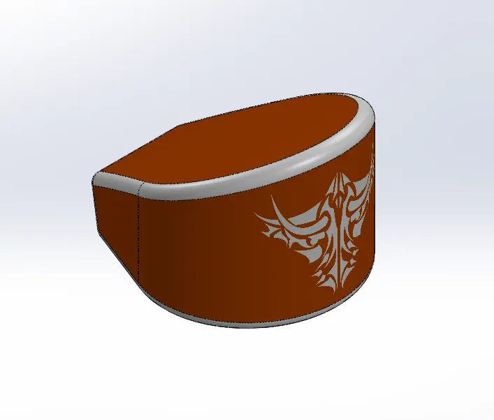
Commands used:
- Arc
- line
- extrude
- combine
- fillet
- shell
Combine: It is used to join or remove to or more bodies and make it a single body by selecting add, subtract or common.
Shell: It is used to convert our solid body into a hollow body at a specific thickness.
7. Pedal:
Pedal is used to place the legs of the riders. It gives comfort to the rider while riding bikes. It is externally attached to the chassis.
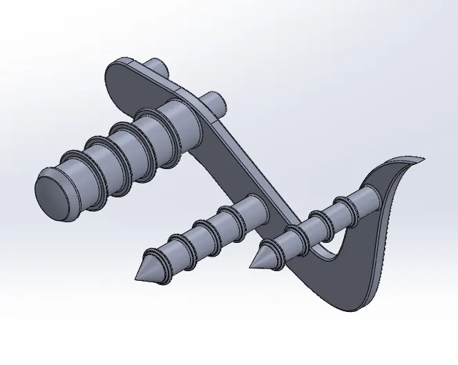
Commands used:
- 2D sketch
- Extrude
- revolve
- dome
- fillet
- chamfer
- linear pattern
Dome: It is used to add a material by creating elliptical or spherical shape by placing some dome value.
Chamfer: It is used to remove material or cut our corners from two sides by giving distance, angle or vertex.
Linear Pattern: It is used to pattern our object according to axis, angle or linear edge by providing entities and distance between them.
8. Front Wheel:
Wheel is a circular object which is made of steel or alloy materials over which a tire is covered. The tire is made of rubber. Rim, rotor and caliper are also attached to it.
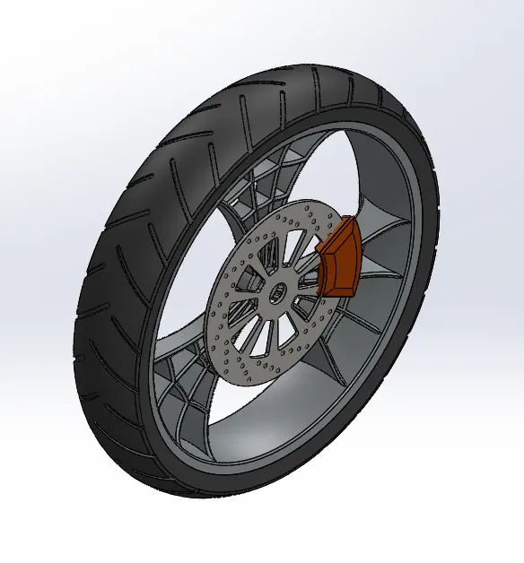
Commands used:
- 2D sketch
- extrude
- extrude-cut
- revolve
- revolve-cut
- combine
- fillet
- circular pattern
- chamfer
Extrude cut: It is used to remove material in normal direction to the object.
Revolve cut: it is used to remove a material by rotating around a reference axis according to its shape and angle.
9. Rear Wheel:
Rear wheel is situated at the rear part of a motorcycle or any vehicle. Rim, rotor, caliper and sprockets are connected to it. A rubber tire is also mounted over outer face of it. This wheel moves when the chain transmit power to it and then the vehicle also move.
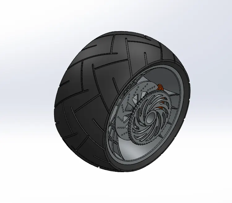
Commands used:
- 2D sketch
- extrude
- extrude-cut
- revolve
- revolve-cut
- combine
- fillet
- circular pattern
- chamfer
10. Front Fork:
Front fork connects motorcycle’s front wheel and axle to its frame. Its suspension system is made up of springing and damping components. They allow the front wheel to react imperfections in the road while isolating the rest of the motorcycle from the motion. The head lights are also connected to it.
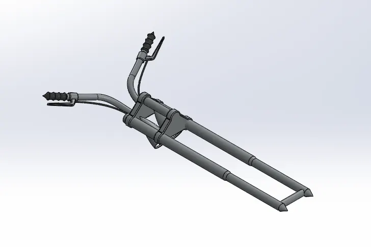
Commands used:
- 2D sketch
- extrude
- revolve
- extrude-cut
- sweep
- combine
- mirror
- move/copy body
- project curve
Move/copy Body: It is used to move/copy the body from one place to another place with or without angle.
Project Curve: It is a 3D curve which can be projected with the help of two different 2D sketches on two different planes.
Sweep: It helps to add the material along the path by following the profile.
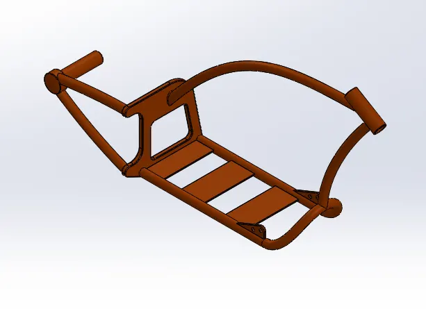
11. Chassis:
It is the base of the motorcycle or a vehicle on which all the components of the motorcycle or vehicle like suspension, wheels, seats, oil tank, gas tank, handle bars etc. are attached which lends the motorcycle its strengths and ability to handle well. It is also called frame or skeleton of the vehicle.
Commands used:
- Sweep
- extrude
- extrude-cut
- chamfer
- fillet
- dome
- split
- combine
- mirror
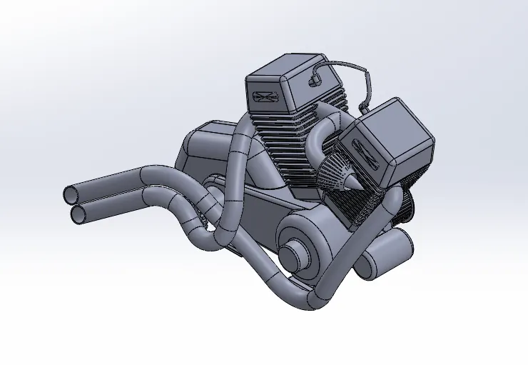
12. Engine:
Engine powers a motorcycle. It converts a chemical energy into heat energy and then into mechanical work. Motorcycle engines are generally two strokes or four strokes IC engine. Other engine types are Wankels and electric motors are used.
Commands used:
- 2D sketch
- Extrude
- extrude-cut
- revolve
- fillet
- chamfer
- dome
- circular pattern
- linear pattern
- split
- mirror
- sweep
- combine
- composite curve
Composite curve: It helps to combine two or more projected curve into a single curve.
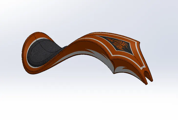
13. Gas Tank:
The main function of gas tank is to hold the fuel. It provides the area for the knees to grip while riding the motorcycle. It supplies the fuel to the engine while riding.
Commands used:
- 2D sketch
- surface sweep
- surface trim
- surface loft
- boundary surface
- mirror
- surface knit
- split line
- fillet
- sweep-cut
- shell
Surface knit: Here we merge or combine two or more surfaces which are not intersected and their gap is negligible or provided on certain conditions.
Surface trim: It helps to remove a part of the surface with respect to other surface which intersects each other completely. We can also keep some portion of the surface.
Split line: It helps to convert our face into two parts with the help of projection.
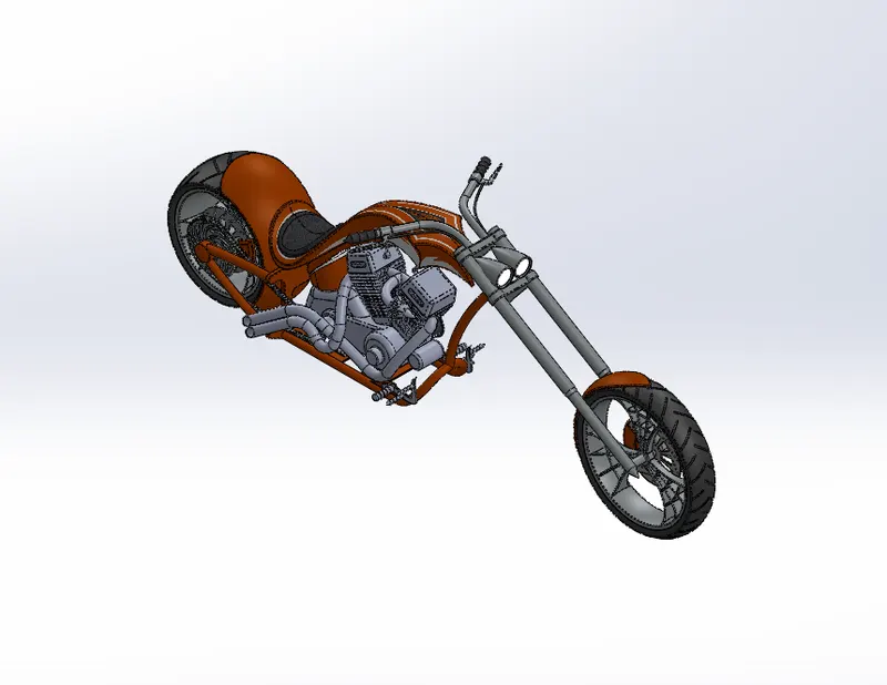
Assembly of American Copper Bike:
Assembly includes all the components in the chassis including transmission belt, oil tank, chain, kickstand, front wheel, rear wheel, front fender, rear fender, pedal, front fork, engine, gas tank. These parts are inserted in assembly and with the help of mates their relations are given.
Commands used:
- Mates
- insert parts.
Insert parts: It helps to insert different parts in the assembly according to requirement.
Mates: It is used to add the geometrical relation between the parts and planes or fixed parts e.g. chassis.
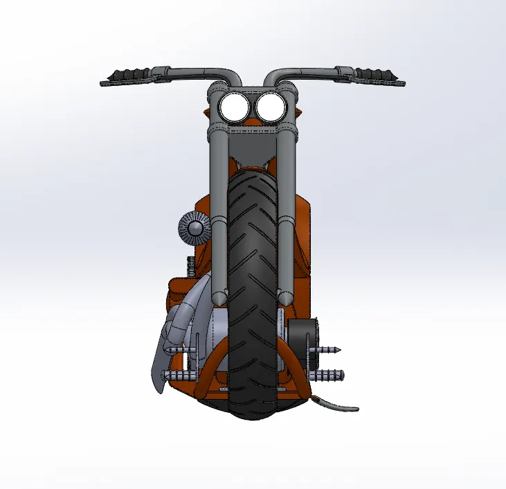
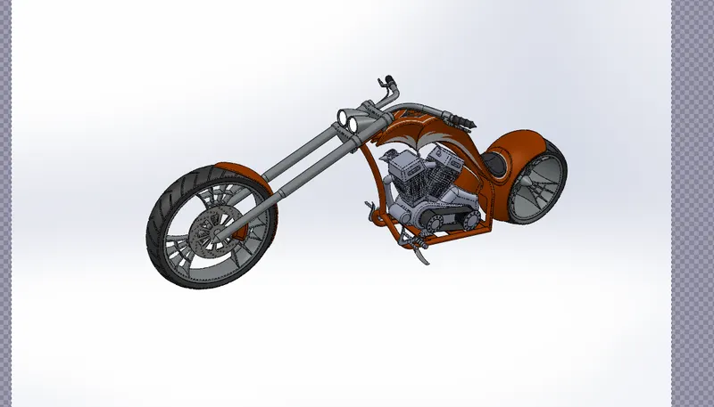
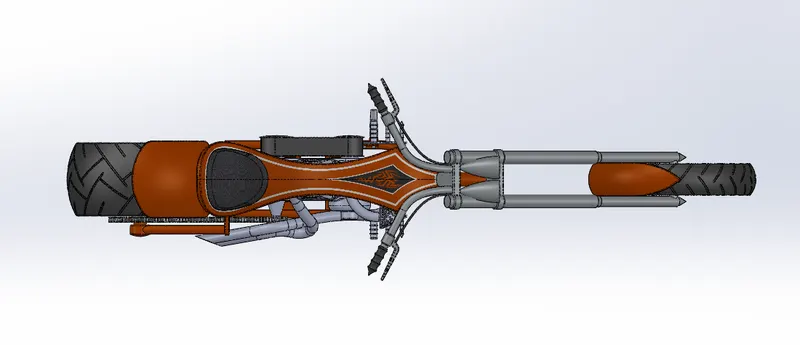
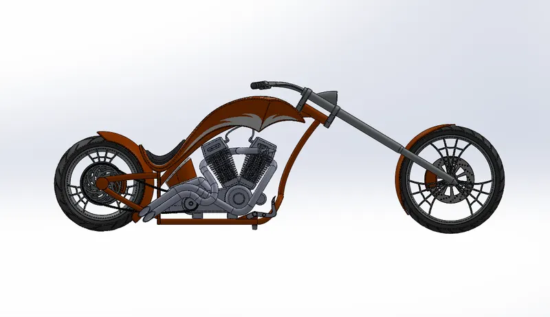
Different Views of assembly:
Side view
Camera setup view
Top view
Front View
Isometric view
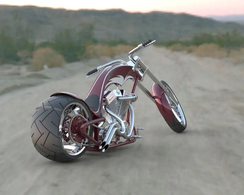
Rendering:
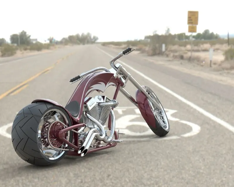
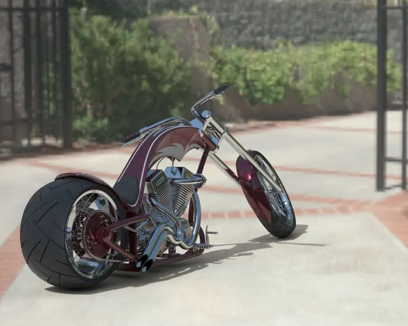
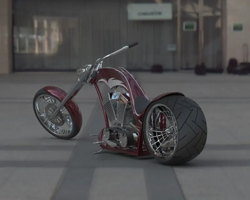
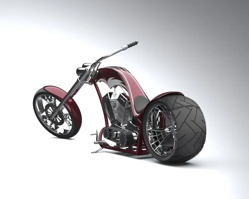
Rendering is the process of creating the photorealistic look of the the model.It is done in two ways
a) Photoview 360
b) Solidworks Visualize
Photoview 360: It is a visualization and rendering solution which is included in the solidworks. It provides a highly interactive environment for viewing designs and creating photorealistic rendering.
Solidworks Visualize: It is a standalone application from solidworks which helps our 3D cad data to create photo quality content from images to animations, interactive web content, and immersive virtual reality to bring our products to life.
Rendered snapshots:
Conclusion:
Hence all the parts of the American Chopper were modelled and assembled using solidworks and the Photo-Realistic Rendering were done using Photoview 360 and Solidworks Visualize.