Week 11 - Final project
TITLE:- Final Project of Door Trim Panel.
AIM:- To Creating a Door Trim panel from given Class A Surface Considering Class A surface , Thickness of component, Attachment mechanical feature With the help of Master Sections.
Give Class A Surface with Master Sections:-
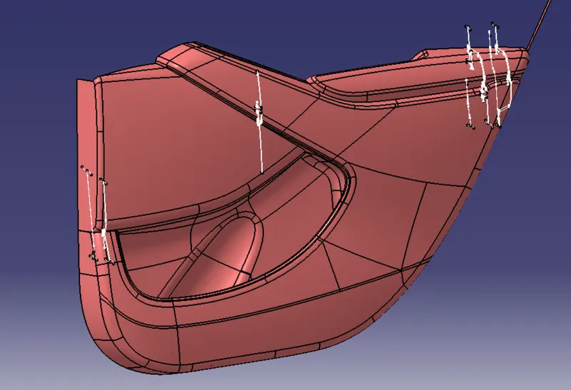
OBJECTIVE:-
- To developing the Door Trim Model of car using CatiaV5 Software.
- Create thicked part from given Class A Surface with Master Section.
- Create Tooling axis for Class A surface and Solid Component.
- Create the attachment feature such as Dog House, Flange, Push Pin, and Heat stakes.
- To performed draft anlaysis using Tooling axis on Given Class A surface and all created solid component.
SUMMERY:-
This project report contains a explain theory on Design life cycle rule and Development of Door Trim panel containing such as Arm rest,Lower Substrate, map pocket and Bottle Holder using given Class A Surface and Master section as inputs, The performed Draft Analysis on all the Class A Surface and Solid Compenent. After Creation a Tooling axis and B Surface to respect to Class A Surface and Creation of class A Surface.The creation attachment feature as per the given master section considere design rule for the creation Dog House, Ribs, Flange and Heat Stakes.
INTRODUCTION:-
Door Trim Panel in a car :- Door trim is an interior component attachment to the inner side of the door and the innear working of the door and between vehicle component and the door. They are expected to meet a varietyod design specification regarding safety , aesthetics. The door panel has evolved from a simple two part system. The door currently have an innear full-width panel consisting of electronic windows, Central Locking System and Speakers. This panels typically of foamed core covered with plastic.
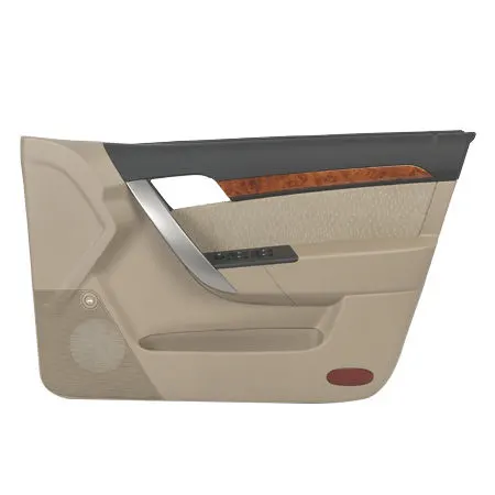
Fig:- Door Trim Panel In a Car
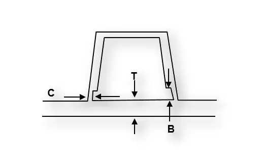
Master Section :- Master section are the guide for Design requirement which decide the component packaging after technical surface.
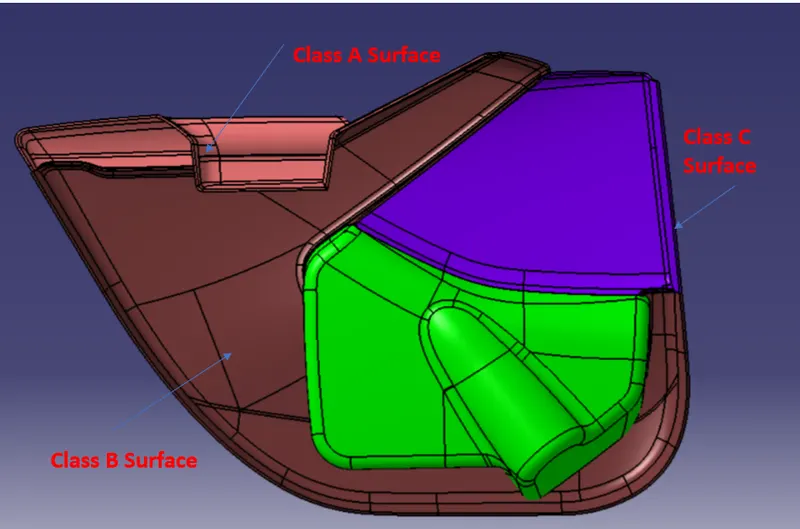
Class A Surface:- A surface made by the designer which is given as an input to the plastic model to work on. It is a aesthetic surfaceand the outer most surface.
Class B Surface:- A surface below a certain thickness from the Class A Surface is Class B Surface.
Class C Surface:- A surface that joints Class A Surface and Class B Surface is Class C Surface.
PROCEDURE:-
Name of Given Class A Surface Below:-
- Map Pocket Upper Class A Surface.
- Map Pocket Lower Class A Surface.
- Lower Substrate A Surface.
- Arm Rest Class A Surface.
1] MAP POCKET UPPER PART:-
1. Firsty , The Creation of the tooling axis need to created in a direction. Which It can Capture component.Generally, A tooling axis will be created perpendicular to the base surface of component.
We need to create Tooling Axis in the Y- direction. Firstly Create point on surface and using this point create line giving in the Z-Direction Axis.This our Tooling Axis. We can see in below Image.
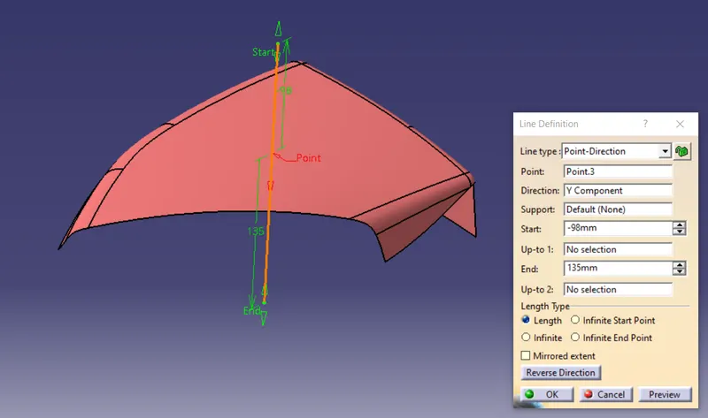
Draft Analysis:-
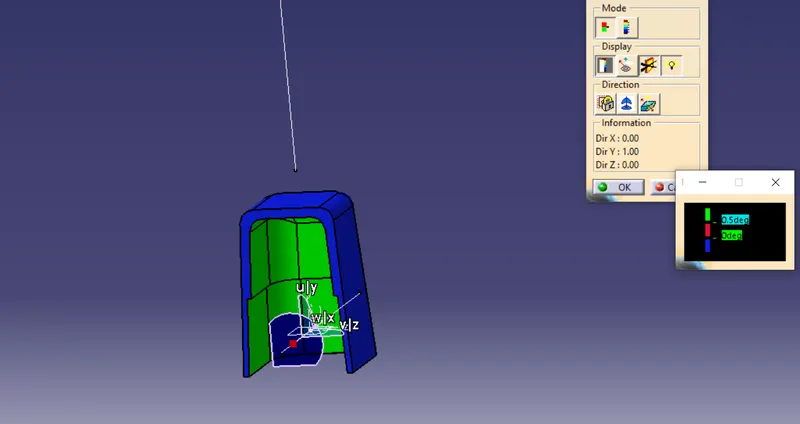
The Draft Analysis command enables you to detect if the part you drafted will be easily removed. This type of analysis is performed based on color ranges identifying zones on the analyzed element where the deviation from the draft direction at any point, corresponds to specified values. All plastic components will have a minimum draft of 0.5 to 3 deg for automotive sheet metal parts the draft will be 7 deg or more.
In CATIA V5 the feature draft analysis dialog box look like this:-
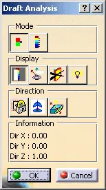
Mode:-
- In the Mode area of the dialog box, select Quick Analysis Mode
- In the Mode area of the dialog box, select Full Analysis Mode
 .The color scale and range of values in the Draft Analysis.x dialog box are expanded.The corresponding colors are displayed on the surface.
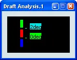
Display:-
- The First box is to open and Close the color scale dialogue box.
-
In the Display area of the dialog box, select Show/Hide color scale
 .The Draft Analysis.x dialog box is displayed. It shows the color scale and identifies the corresponding values for the analysis
 -
In the Display area of the dialog box, select On the Fly
 and move the pointer over the surface.The following information about the current pointer location is displayed
 - Green arrow :- The normal to the surface
- Red arrow :- The draft direction
- Blue arrow :- The tangent to the surface
- Circles :- The plane tangent to the surface
- Value (reverse highlighted):- The angle between the draft direction and the tangent to the surface.
- Value (unhighlighted): The cone angle (the angle between the axis of the cone and the draft direction ).
- Click the Light effect button and the colors of the analysis elements react to the light source.
Direction:-
 The First check box is locked is locked direction icon which is used for lock the direction of compass after selecting the specifird direction.
 click on compass icon to specify the new pulling direction to remove the part.
 Click the Inverse button to automatically reverse the draft direction.
Observe The color Range:-
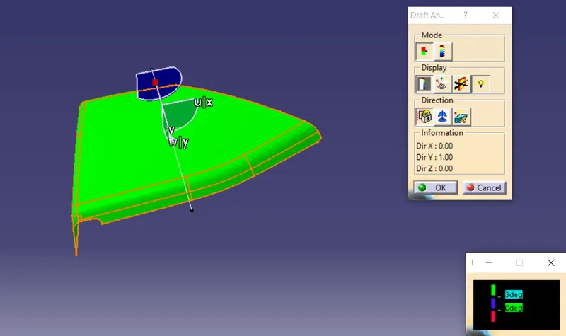
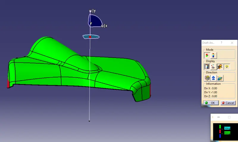
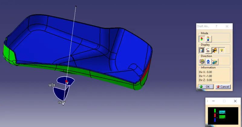
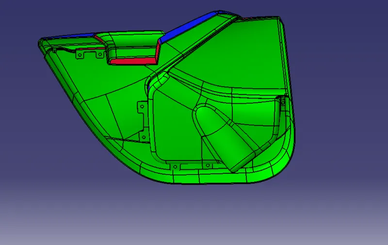
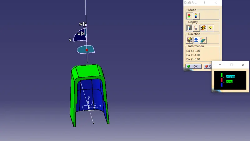
- Green :- Draft value above 3 deg.
- Red :- Draft Value below 0 deg.
- Blue :- Draft Value Between 0 to 3 deg.
2. Draft Analysis on Class A Surface:-
3. Creation Class B Surface. We have offset class A Surface of Map pocket Upper suraface 2.5mm. Next , Creation Class C suraface , First extract the boundarie of class A suraface. After Extracting the boundaries We can perform Smooth operation on Extracted boundaries.Create continuous tangent surface. after using Sweep option. Create class A surafce by sweepe Boundaries of the Class A surface.
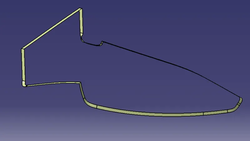
4. To Joining class A With the Class C Surafce. Then Trim Class B Surface this joined Surface and We have get the final Closed surface.
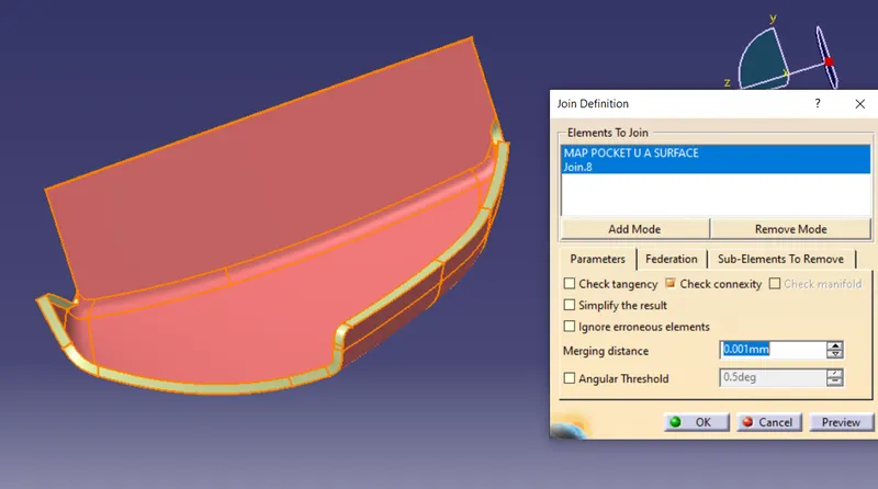
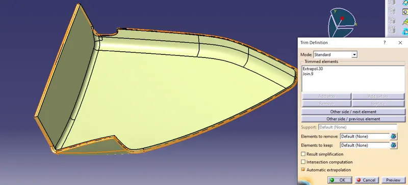
Check if there are any gap after joining the surface by using the boundari option.To get Final Output. we can see below image,
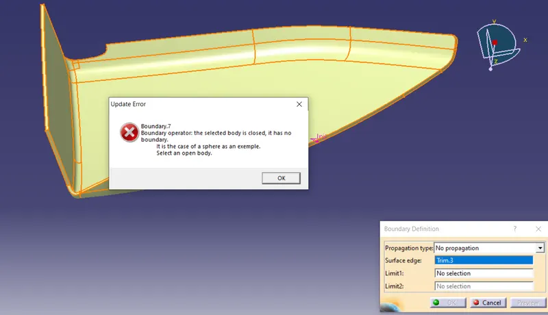
Now, we need t closed suraface them to form thick body. Go to part body and using the Close Surface option. A solid body from closed surface fromed.
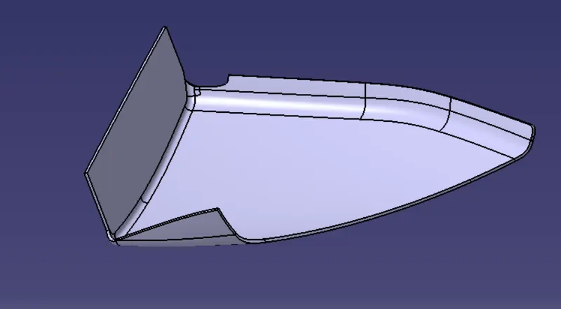
5] Perform Draft Analysis on Solid Part:-
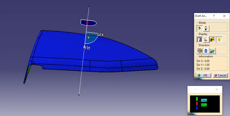
The Draft is required to eject the part from the mould properly. Firstly we need to change the material mode and After Click on Compass red point and Drag on Tooling Axis and Click on any surface. above surface Green color mean the draft angle Above 3 deg.
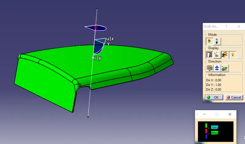
This color show draft angle Between 0 to 3 deg.
2] Map Pocket Lower Class A Surface:-
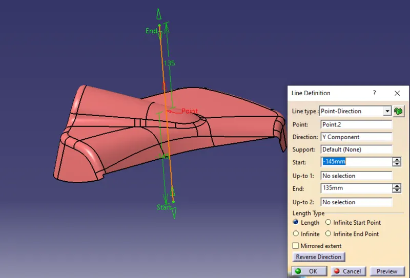
6. Create tooling Axis, Create point on suraface and select line option and create tooling direction Y- component.
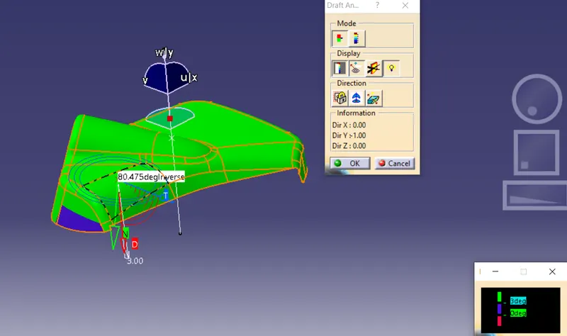
To performing Draft analysis on Class A surface of Map Pocket Lower.
7. Offset The Class A Surface above from Map Pocket Lower 2.5mm.
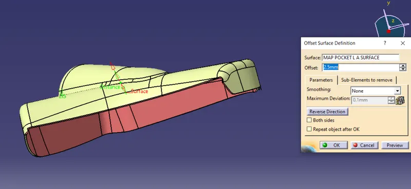
8. After To Create Class C Surafce, Procedure the same as mentioned for the above parts.
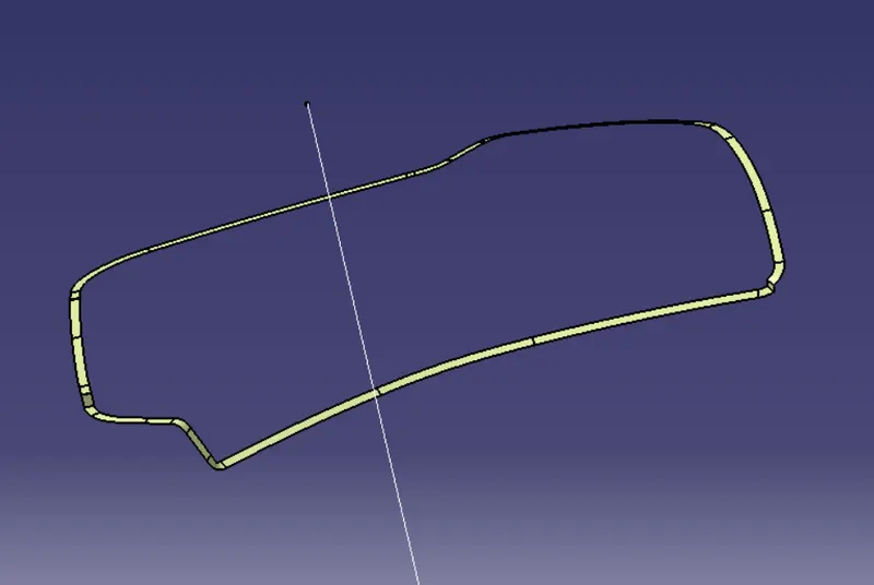
9.After Trim of joined class A surafce and Class C surafce with Class B Surafec. we get closed Surafce body.
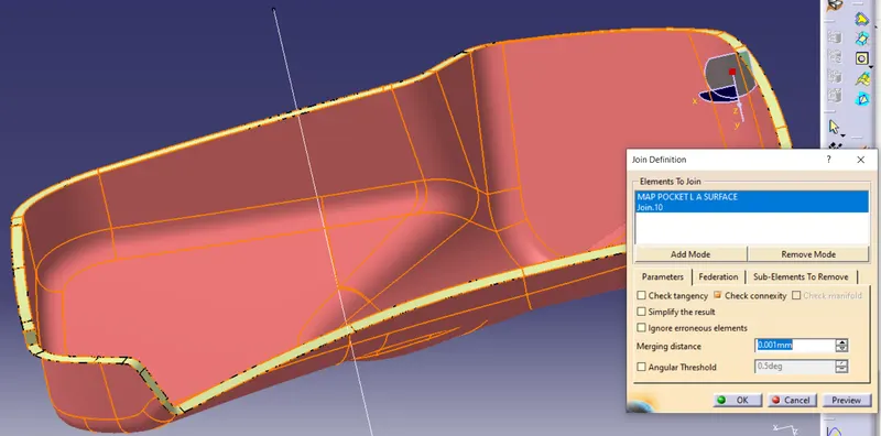
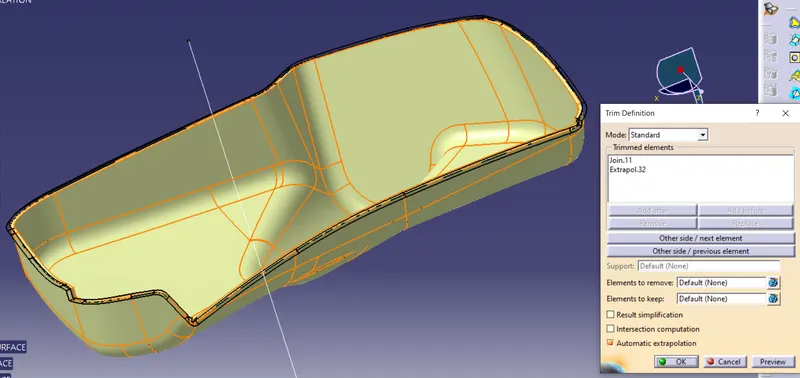
A solid body from closed surface fromed.
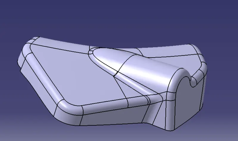
10. To perfomed draft analysis on solid body:-
3] Lower Substrate A Surface:-
11.To create the Tooling Axis in the Y- Direction. This line will give us the Tooling Direction.
This is Class A Surface of lower Substrate
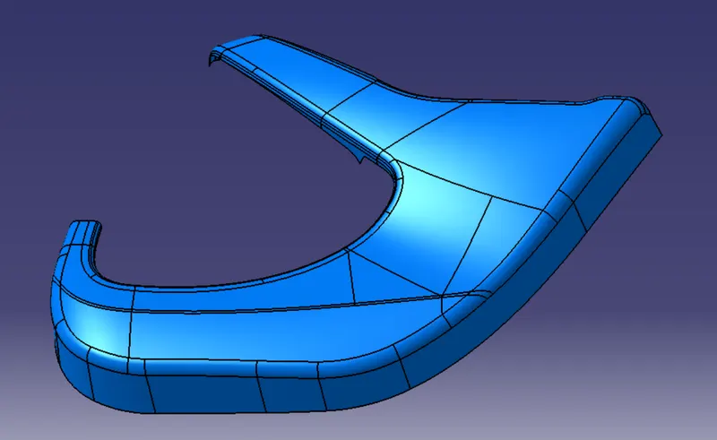
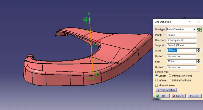
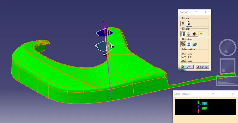
12. Performing a Draft Analysis on Class A suraface of Lower Substrate.
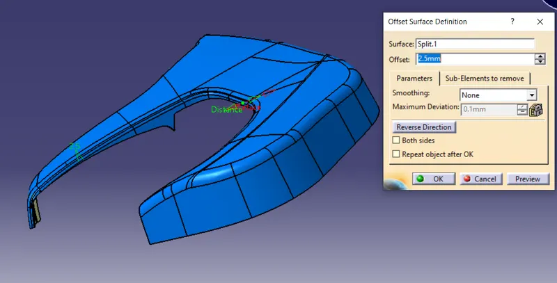
13. Class B Surafce-
To create class B Surafce ,offset the class A surface by 2.5mm.the thickness of component measure from the Master Section.
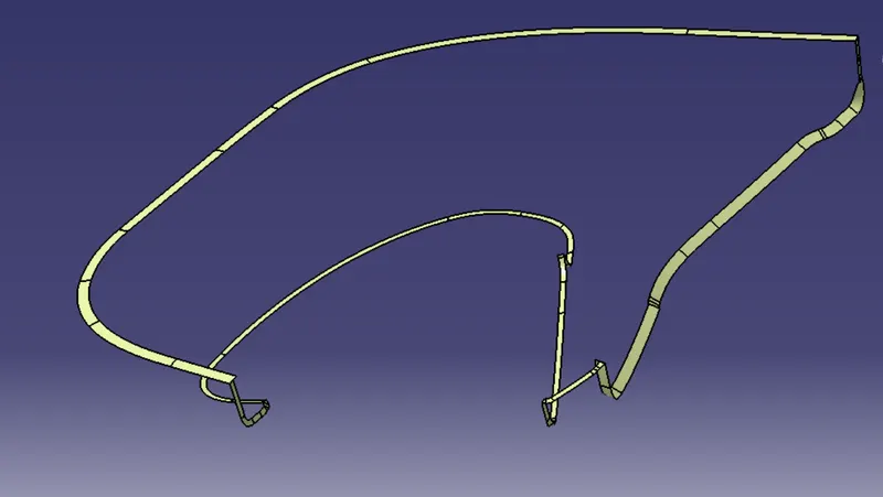
14. Create Class C Surface:-
Firtly Exstract the boundaries of class Class A Surface.We have need to smooth curve. after we go to sweep tool and click on boundary of class A surafce.
note:- It is not possible to crate class C surafce and the Boundary extracting seperatly and the sweep operation also need to seperatly operation.
15.After joining Class A Surafce with Class C Surafce and then Trim the Class B Suraface with Class A & Class C Surafce. To get final closed suraface body.
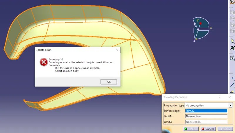
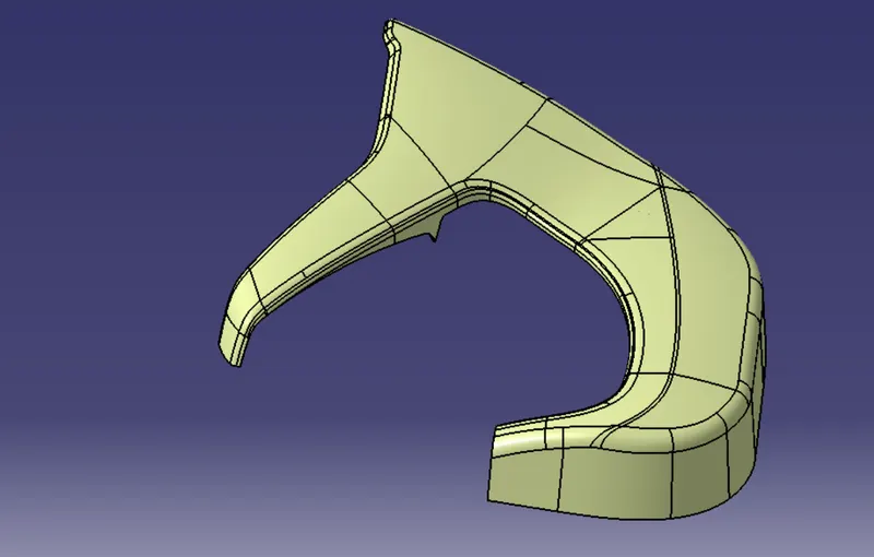
Closed solid body
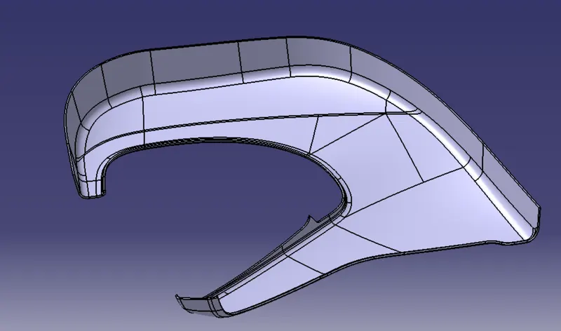
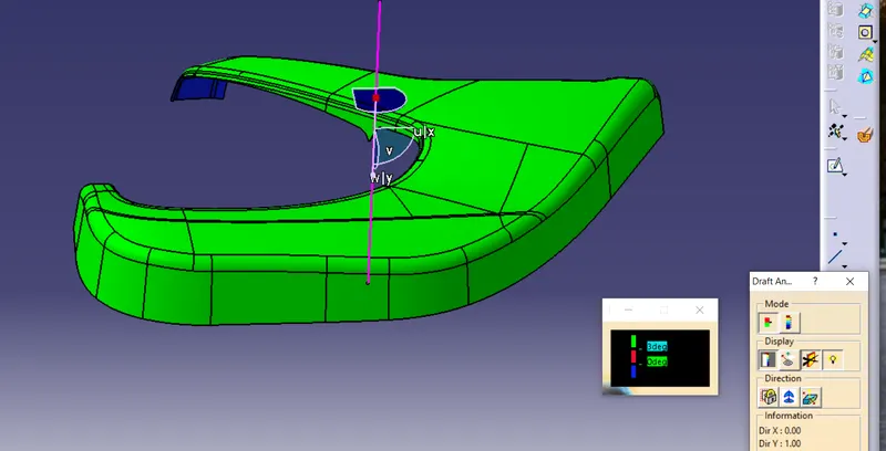
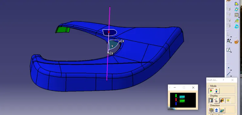
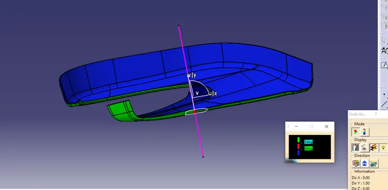
16. Performing Draft Analysis on Solid closed Component of Lower Substrate. We can seen below Images
4] Arm Rest:-
Creation of Tooling Axis:-
Extract the Base surface of class A surface and create point on the middle of Surface and insert the Axis system.Intersecting creation y direction and bisecting between two line create tooling Axis.Name as main tooling Axis for Door Arm Rest.
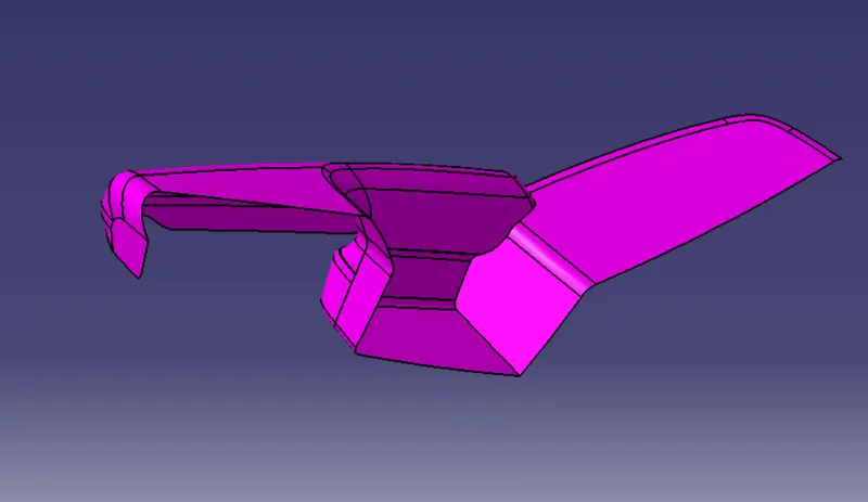
Class A Surface of Door Arm Rest:-
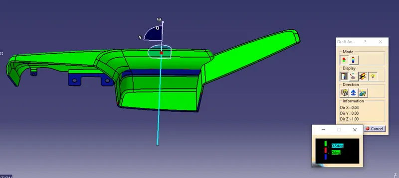
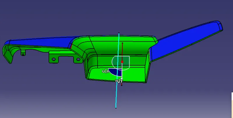
17.Now the last part of Door Arm Rest part which we have to split into 2 parts for the tooling axis. for that we have the 2 part for it 2 Different tooling axis. Created main tooling Axis for Arm rest and Create Side core axis anf after performing Draft Analysis on Door Arm Rest.the Draft analysis at 3 deg.we can see below.
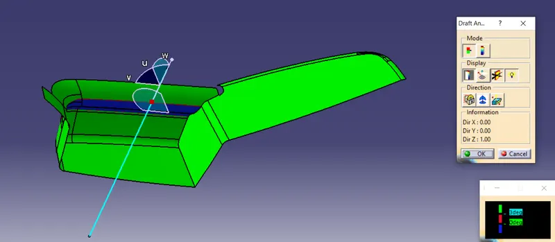
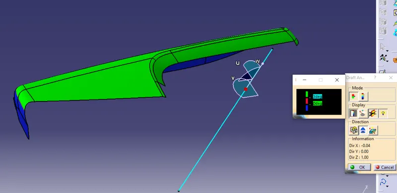
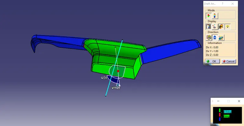
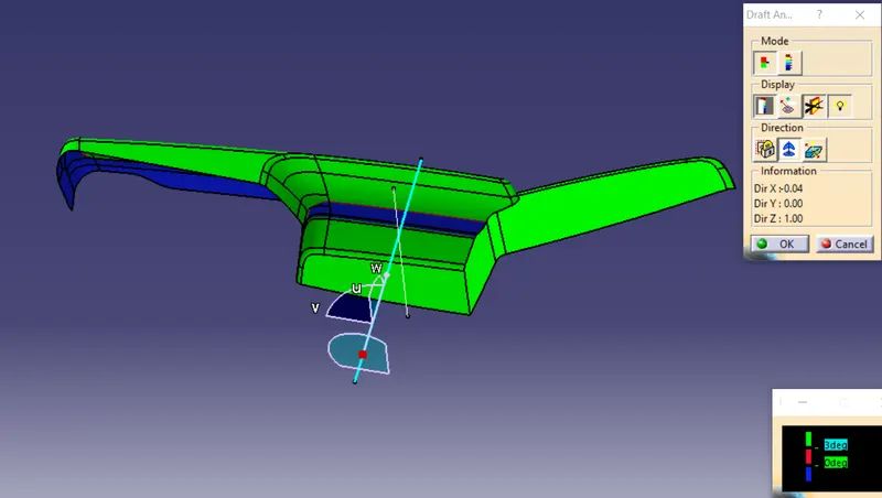
We check the boundaries of Arm rest. we have find small boundries open and Joint it. we can see below
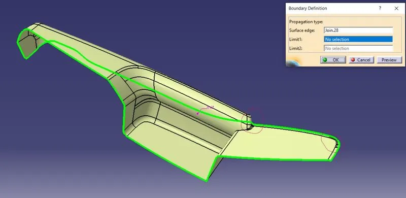
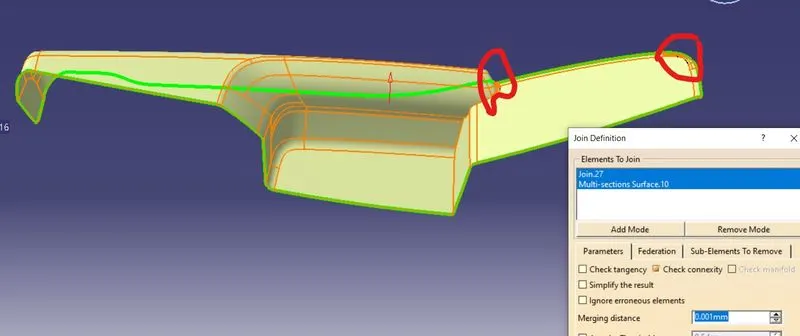
18. Offset the class A Surface Seperatly at 2.5mm and then joint it. to get Class B Surface.
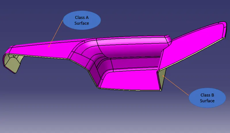
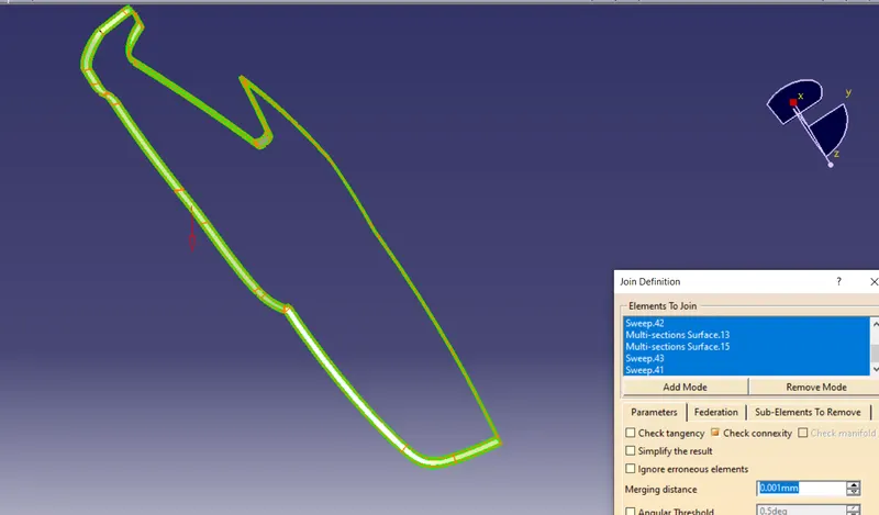
19. After created Class C Surface Using 'Sweeping' command with reference to the surface of the Arm Rest Class A. To get Class C Surface. Join the class C surafce with Class A Surface.
20.Trim the Joined Class A Surface& Class C Surface with Class B Surface. To get Close Surface body.
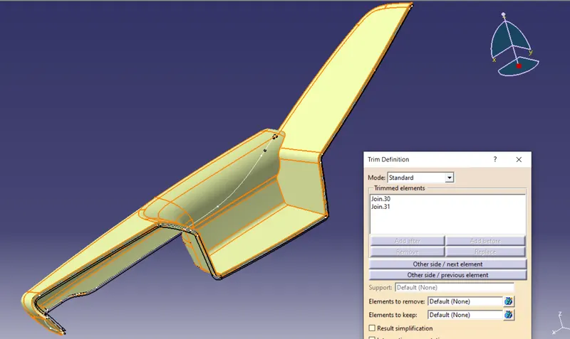
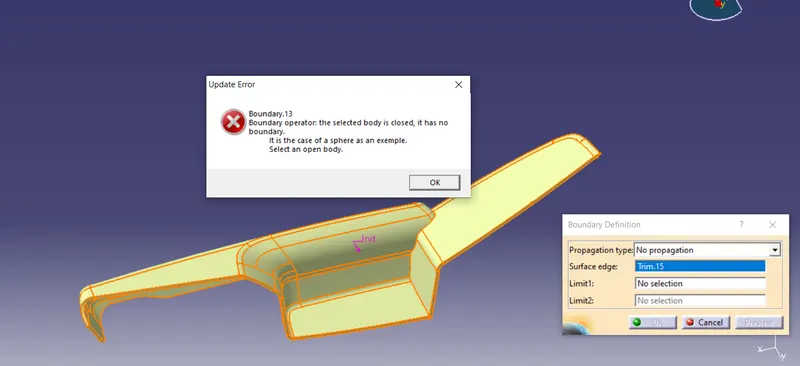
To get Close Surface Body
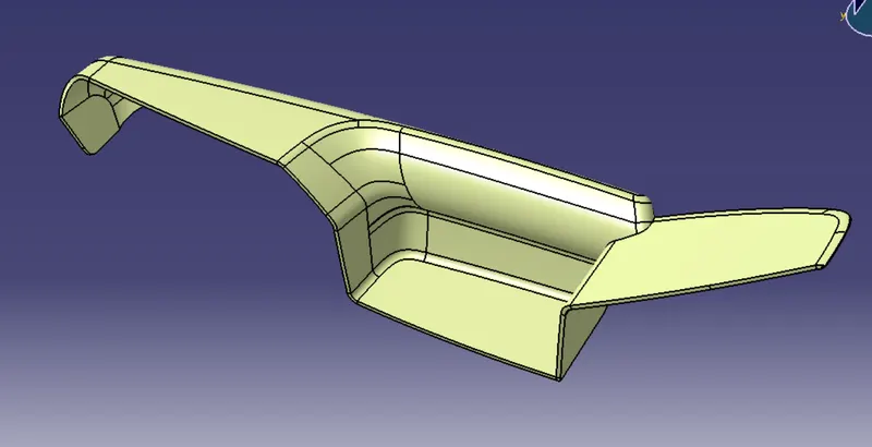
After go to part body and To create Close Surface Solid Body.
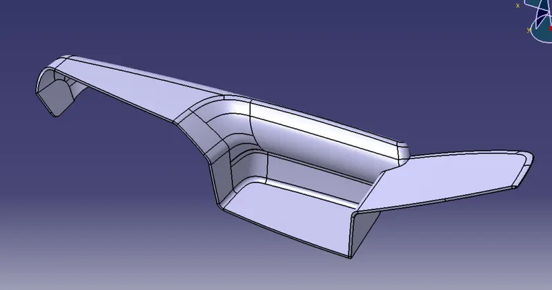
21.Performing Draft Analysis on Solid Close Surface and We can see below
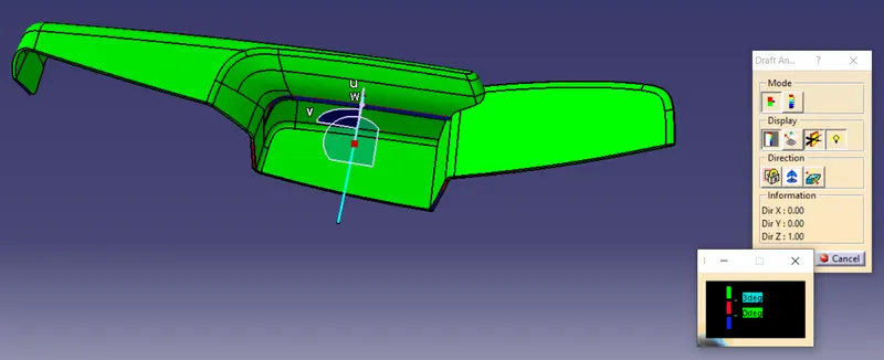
To Get Final Solid Body:-
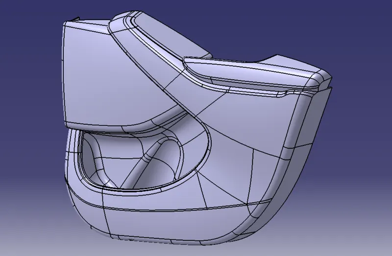
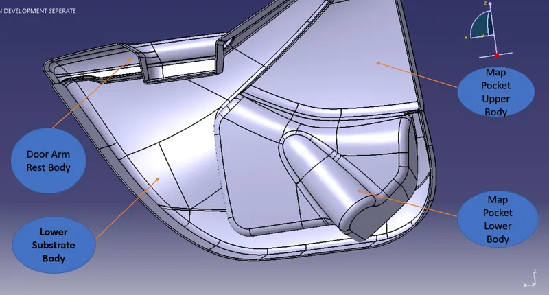
22. Draft Analysis For Final Solid Body:- The same procedure is followed similar to the class A Surafce.The procedure mentioned above.
To Create B Side Features:- Name as Flanges,Screwboss, Heat stakes, Dog House, Ribs and Push clip.
Create the B Side feature based on the give master section .By following the master section and design rules the B Side Feature are Desined.
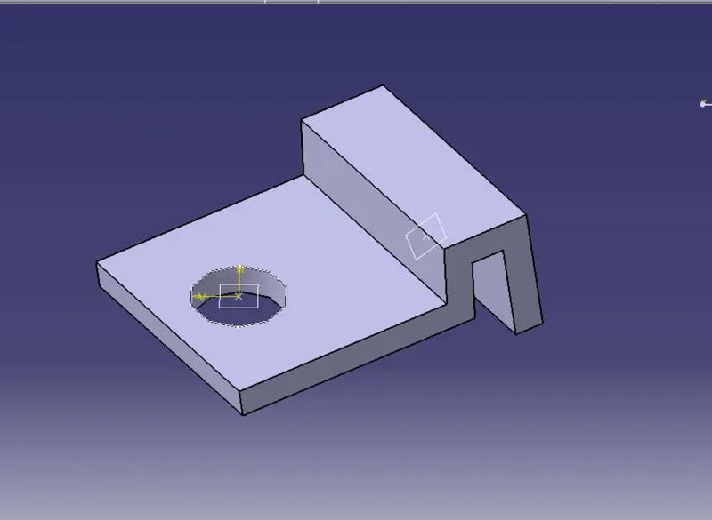
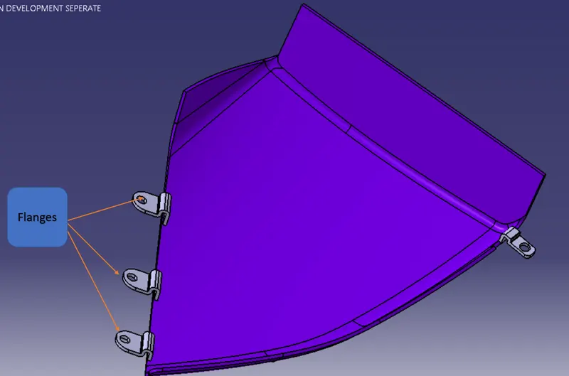
Cration of Flanges:- The Flanges created as per given master section,
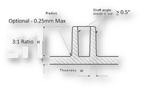
Ribs Creation Design Rules:-
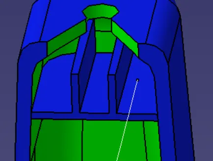
- Draft: 0.5 deg per side (minimum),but this value should not be high enoughthat it will cause failure for other consideration.
- Thickness of rib: 0.4*t where, t is the wall thickness.
- Height: >5 time the wall thickness i.e.5*t
- Spacing: 3:1- steel height/width ratio (maximum).h/w=3or2(preferred) where, h is the height of rib and w is the space between two ribs.
- Maximum thickness at the tip:0.75
- Radius: 0.25 maximum
- Rib on opposite side of the wall should be offset
- Rib should be conected to other structural feature where possible.
- Rib root thickness should not be more than 30% of the wall thickness.
Procedure:-
1. Firstly create Sketches For Ribs.
2. Go to Part Workbench and performing Pad on Sketch give thickness of Rib 1mm.
3. Performing Draft 0.5 deg on side and performing Boolean operation.
4. After attach the feature to main body.
Heat Steakes:- Heat Steakes are used for to constraints the (DOF) Degree of Freedom. The Distance between Two Heat Steake Minimum 50mm To Maximum 100mm.
Procedure:-
1. Create Heat Steakes Using Referance of Given Master Section. The Circle Diameter 7.5 mm.
2. Go to Part workbench and perform the thick part.
3. After performing Draft 0.5 deg outer side and Use Copy and Translate point to point option to create a New heat Steake in a new location.
4. Perform the Union Trim per heat steakes to attach the main body.
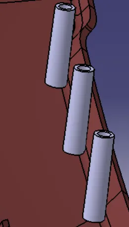
SCREW BOSS DESIGN:-
They are used for the purpose of mating two parts. They have hole in them which accepts the threaded part of the fasteners such as screw.
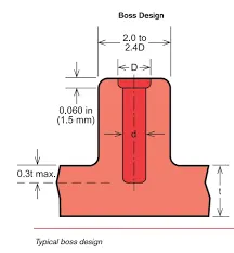
Bosses find use in many parts designs as point for attachament and assembly.The most common variety consists of cylindrical projections with the hole designed to receive screws, threaded inserts, or other types of fastening hardware.As a rule of thumb, the outside diameter of bosses should remain within 2.0 to 2.4 time the outside diameter of the screw or insert.
General Guidelines for Bosses:-
- Draft - 0.5 degrees on walls of boss
- Thickness - Typically 40%* of the nominal wall at the base.
- Height to Diameter Ratio - 3:1
- Radii - 0.25mm maximum radii.
- Avoid marging the screw boss into wide wall.
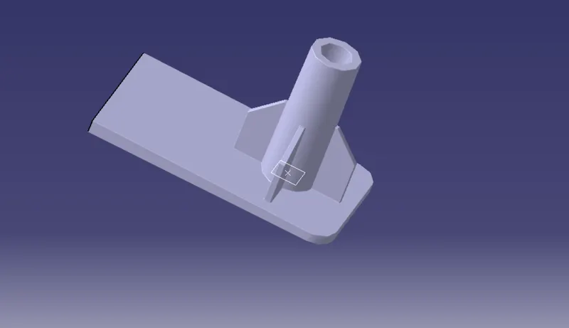
Screw Boss :-
To Create Screw Boss with the help of given Master Section.
DOG HOUSE:- The Dog House is an enginering feature used in plastic trim design. Dog house are used as supporting features. Sometimes other engoneering feature like snaps, locator etc. are moulded on them to increase their strength.Dog house are subjected to draft analysisto prevent breakage of the component during ejection from the mould.
General Guidelines for Dog House Design :-
- Minimum height: Less than 6mm causes steel condition.
- 3:1 ratio of steel width to height. but 2:1 is preferred.
- Minimum width: 3:1 ratio of steel width to height. but 2:1 is preferred.
- Draft minimum: 1.5deg.
- Sink Saver: Height= 40% of nominal.
- Thickness. Width=3.0mm-6.0mm.
- Optimal radius:25mm.
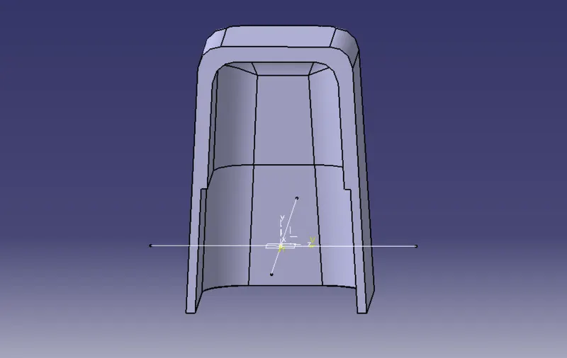
Dog House Creation:- The Dog House is used to Mount the Push Clip and Give the Strength to the Body.
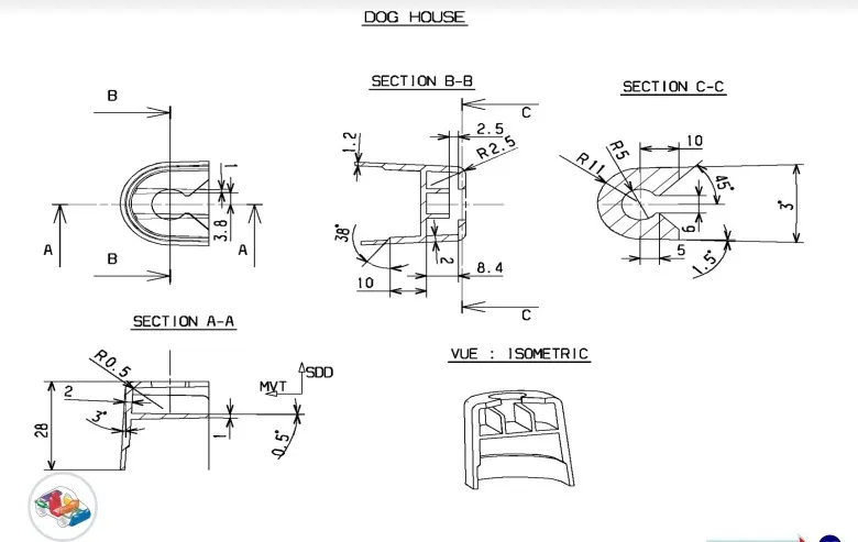
1. Firstly Create the sketche for dog house and Extrude it.
2. Go to part workbench create the thickness of dog house 2mm and perform the draft 3 deg angle on both side wall.
3. After create Ribs and Use Copy and Translate point to point option to diference location.
4. Using Union Trim opertion to attach the dog house main body.
Performed Draft analysis on Dog House.
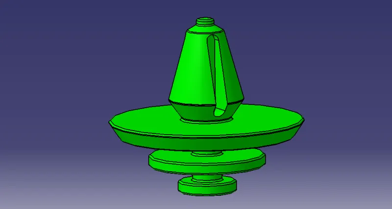
Given Push Pin/Clip:- Push Clip are Attached to Dog House which used for Lock the component and fit in it.
Assembly Workbench:-
- Go to the new product and insert all the existing component with the product.
- Move along the X Y Z direction using Manipulation command.
- Insert new part with the constraine.
- After fix the constraine not movable.
- After Push Pin one by one Coincidence point with reference point of the Dog House.
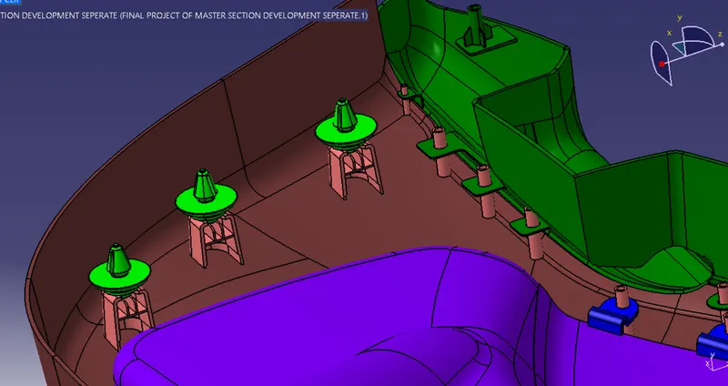
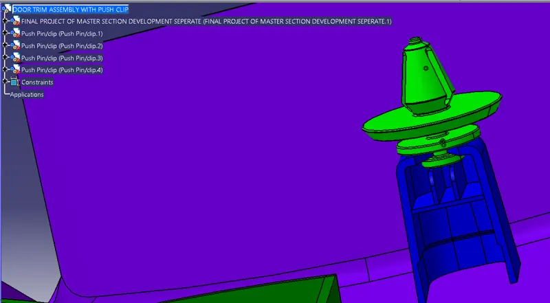
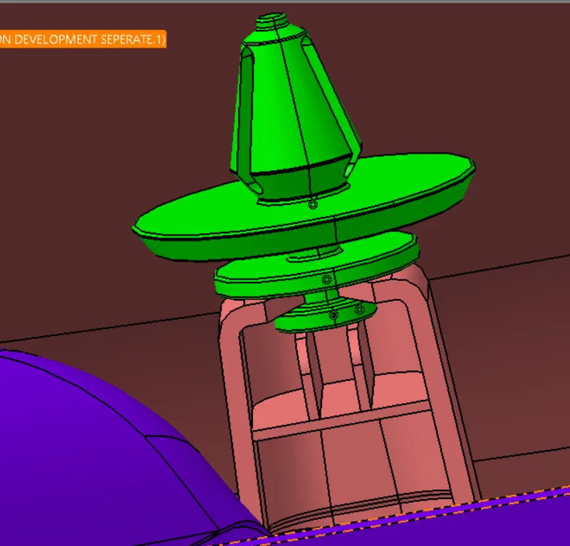
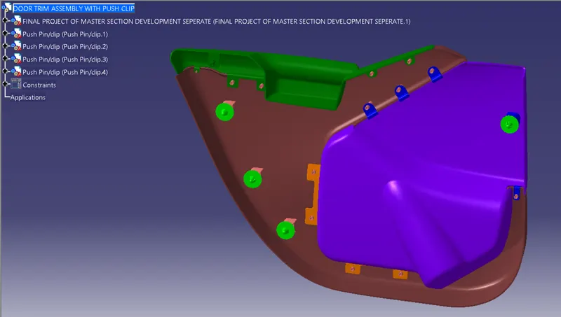
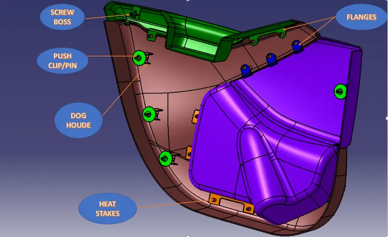
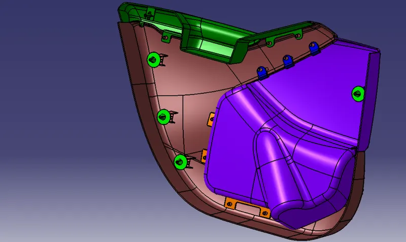
Fig:- Door Trim Part with All B Side Features.
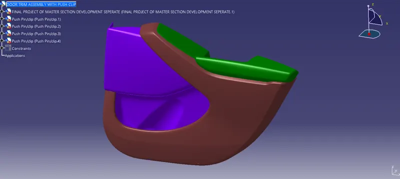
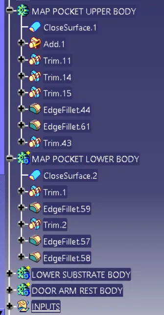
Tree Structure:-
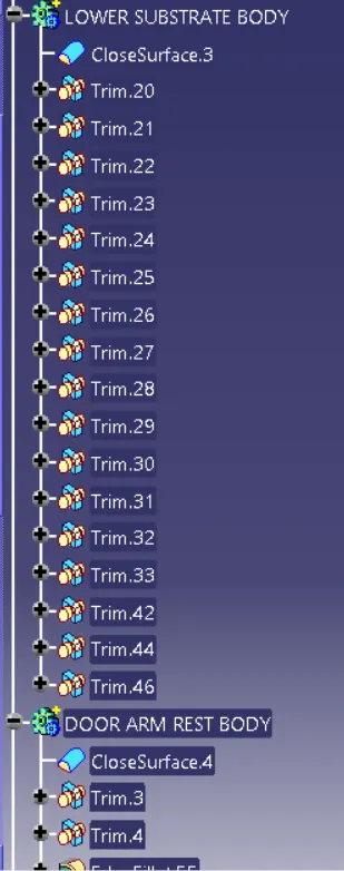
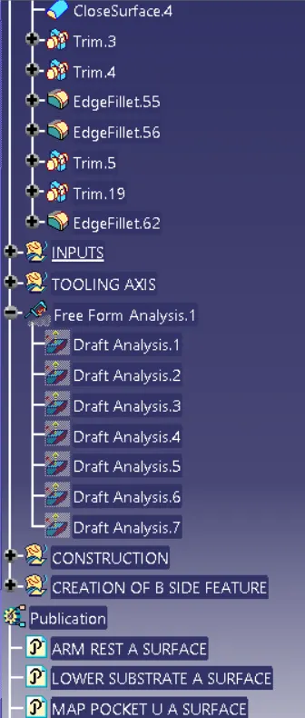
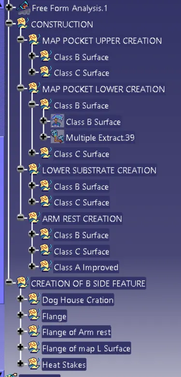
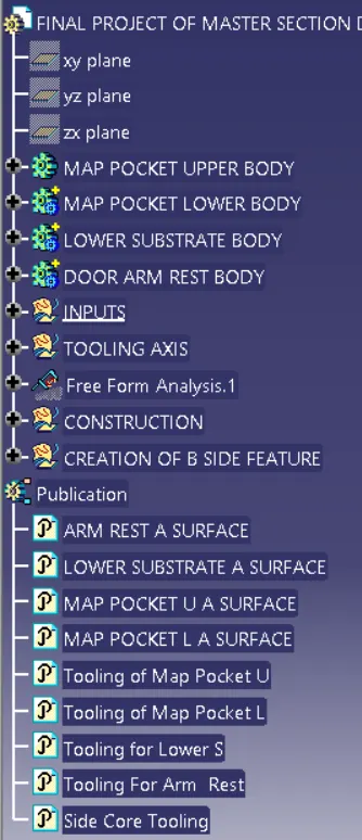
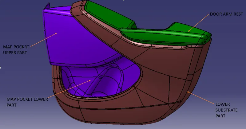
Final Door Trim Panel With Closed parts and B Side Enginering Feature:-
Output:-
The complete created solid model for the give Class A Surface. We have created Engineering Feature and Performed the Draft Analysis for all the component.
Conclusion:-
- Created thickened part with the given Class A Surface and following given master section thicknees-2.5 mm.
- Created the mounting engineering feature such as Dog House,Heat Steake,Ribs,Flanges,Push Pin/Clip,Screw Boss etc.
- Performed Draft Analysis on Solid thicked part and B side Engineering feature.
- Gokulraj SelvarajHi, pls share the final project files for catia platic design . It's useful for my practices. Send the file into my mail id [email protected]
- Gokulraj Selvaraj[email protected]