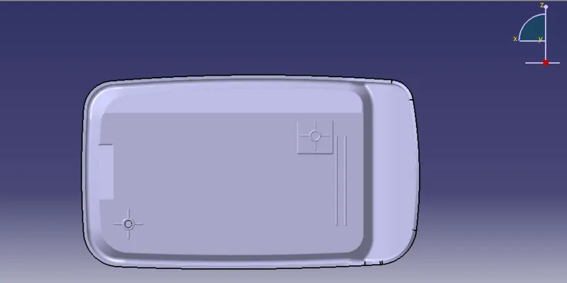
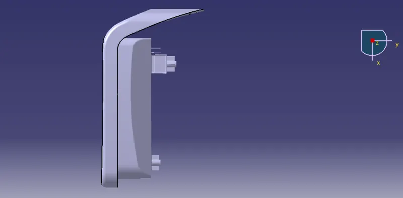
Week 9 - Attachment Feature Creation - Challenge 2
AIM:- To Create the Boss and Dog House for the coin holder considering the design rules.
OBJECTIVE:-
- To Create The Boss and Dog House.
- The tooling axis creation using particularly the Bisecting method.
- The draft analysis report on Dog house and main Component.
THEORY:- Class B- surface contain all the engineer data required for model to be completed.This data involved designing of various features. Some of the major features of the B-side are-
1) Ribs Design.
2) Screw Boss Design.
3) Dog House Design.
SCREW BOSS DESIGN:-
They are used for the purpose of mating two parts. They have hole in them which accepts the threaded part of the fasteners such as screw.
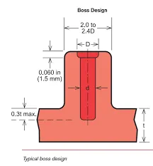
Bosses find use in many parts designs as point for attachament and assembly.The most common variety consists of cylindrical projections with the hole designed to receive screws, threaded inserts, or other types of fastening hardware.As a rule of thumb, the outside diameter of bosses should remain within 2.0 to 2.4 time the outside diameter of the screw or insert.
General Guidelines for Bosses:-
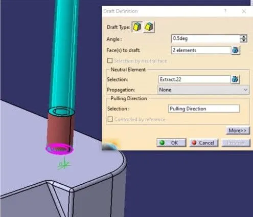
- Draft - 0.5 degrees on walls of boss
- Thickness - Typically 40%* of the nominal wall at the base.
- Height to Diameter Ratio - 3:1
- Radii - 0.25mm maximum radii.
- Avoid marging the screw boss into wide wall.
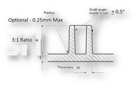
DOG HOUSE:- The Dog House is an enginering feature used in plastic trim design. Dog house are used as supporting features. Sometimes other engoneering feature like snaps, locator etc. are moulded on them to increase their strength.Dog house are subjected to draft analysisto prevent breakage of the component during ejection from the mould.
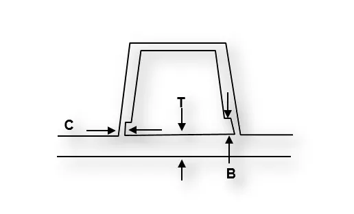
General Guidelines for Dog House Design :-
- Minimum height: Less than 6mm causes steel condition.
- 3:1 ratio of steel width to height. but 2:1 is preferred.
- Minimum width: 3:1 ratio of steel width to height. but 2:1 is preferred.
- Draft minimum: 1.5deg.
- Sink Saver: Height= 40% of nominal.
- Thickness. Width=3.0mm-6.0mm.
- Optimal radius:25mm.
PROCEDURE:-
Creation of Tooling Axis:-
1. Extracting the base surface of Class a surface and Crate a point at the center of the base surface using point defination.
2. Create an Axis system at the point that is created at the using Axis System by defination secting the point.
3. Next create and Intersection in the ZY Plane by intersecting defination for the center of Coin holder.
For Screw Boss:-
4. First make a positioned sketch on the Z-X plane on the Screw Boss.
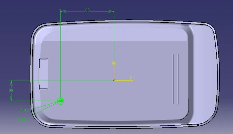
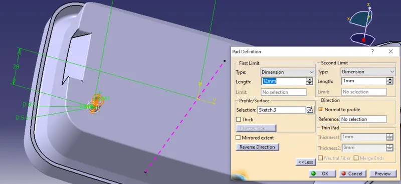
5. Pad the sketch and we get the cylinder which is initial screw boss structure.
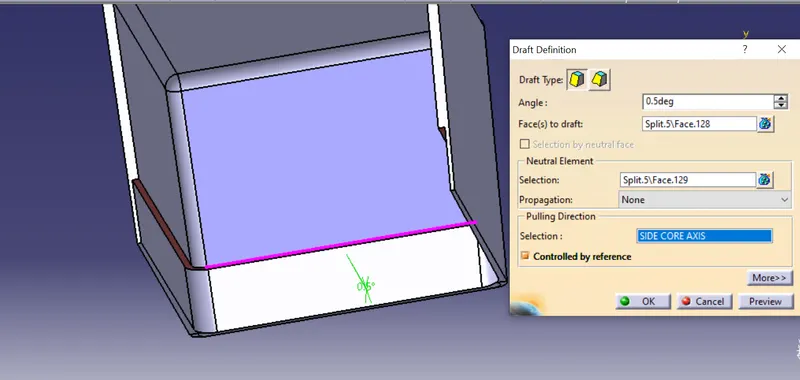
6. Draft both the cylindrical faces it with minimum 0.5 deg draft.
7. Make sure the wall thickness is in accordance with the design standards. i.e. 0.4*t.First make the sketches of the gussets as shown in the images.
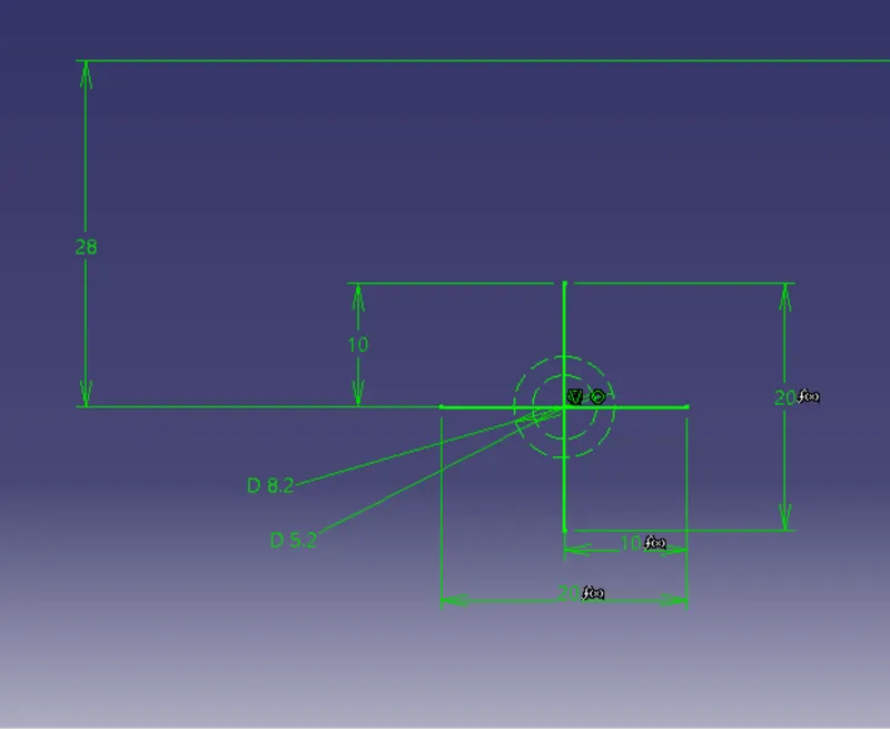
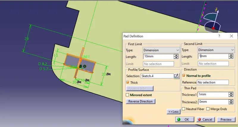
8. Then pad the sketches with thick feature on and ensure that the resulting pad is in the middle.Make sure the thickness is an with the design rules on the ribs i.e.0.4*t and also the height should not be more than 5*t.
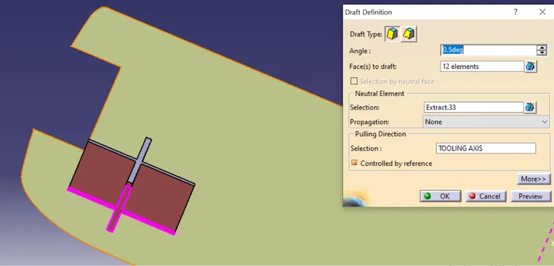
9. Give Draft to the gussets i.e.Minimum 0.5deg.
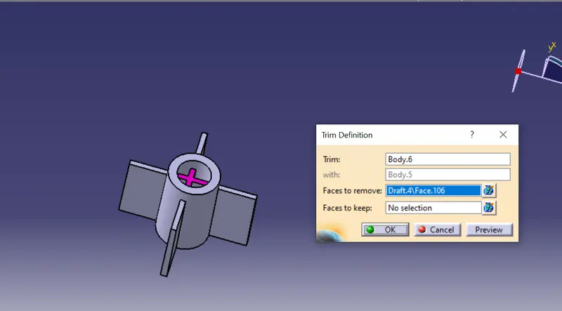
10. Now, Union-Trim it with the screw boss and Assemble it to the main coin holder.
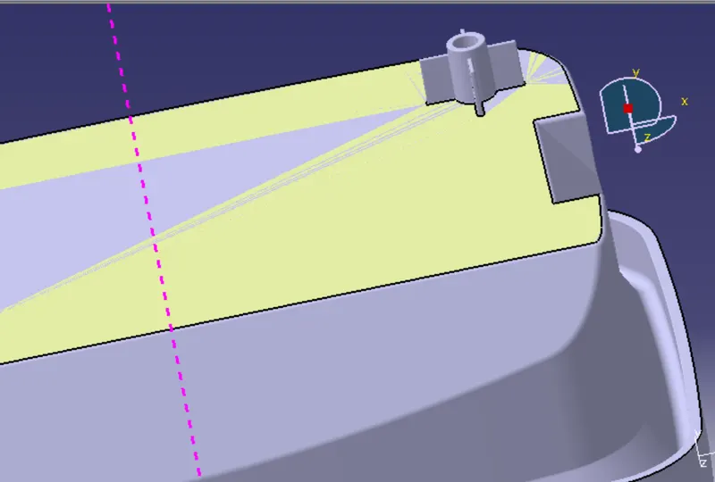
11. Give Minimum edge fillet to it i.e. 0.25 mm.
12. Next, Translate the Screw boss using Cordinates.
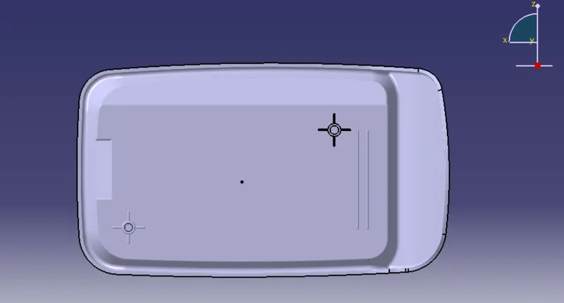
Creation Dog House:-
13. Copy the existing Screw Boss.
14. Paste special in the main part file.
For making Dog House:-
15. Make a rectangle to enclose the screw boss in it but make sure it is open from one side.
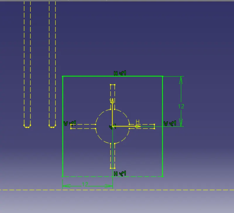
16. Sweep it with Tooling axis as the pulling direction and give minimum Draft of 1.5deg inwards.
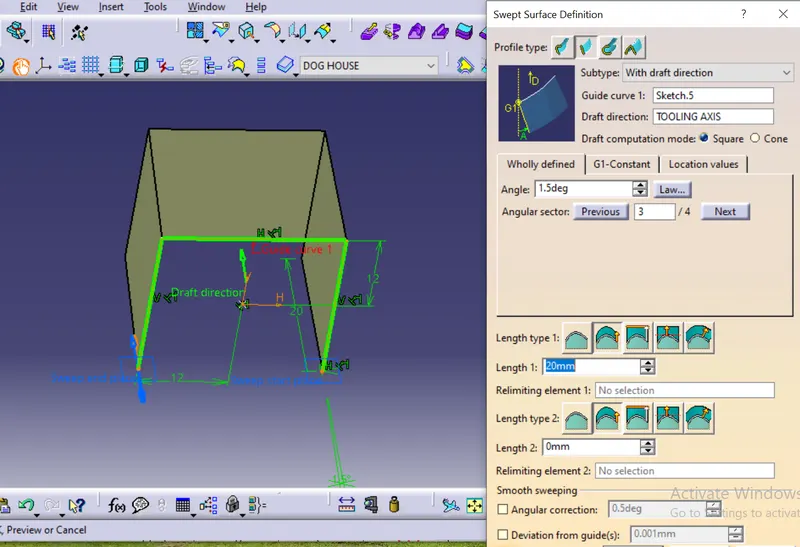
17.Now, Untrim The base surface
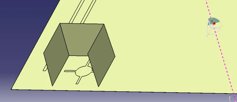
18. Enclose it from the top by using the off-set of Extract of the base of class -A Surface . The offset Distance determine the dog house,it according tp the design rules. and Trim Them.
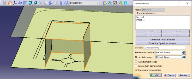
19. Now, Go to part design and Thicken the surface.
20. The inwart face of the dog house should be drafted to, so give them a draft od 0.5deg.
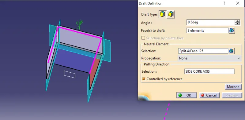
21. Use the Same Extract of class A surface and offset it at the height of 3mm- 6mm.
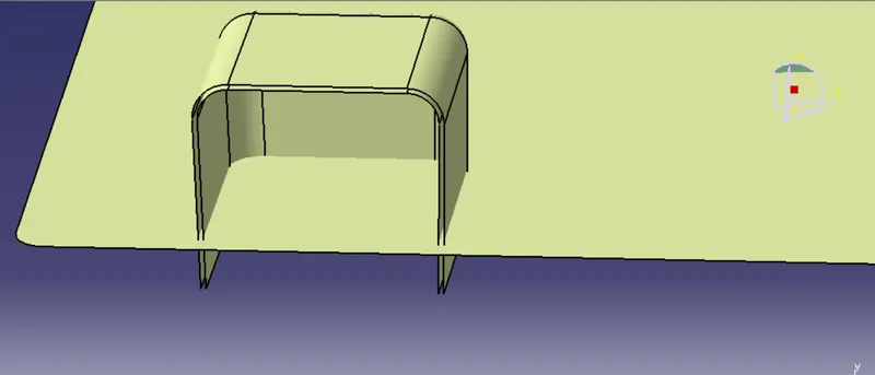
22. Extract the inside face of the dog house and offset it outward at 0.4*t and Trim Them together.
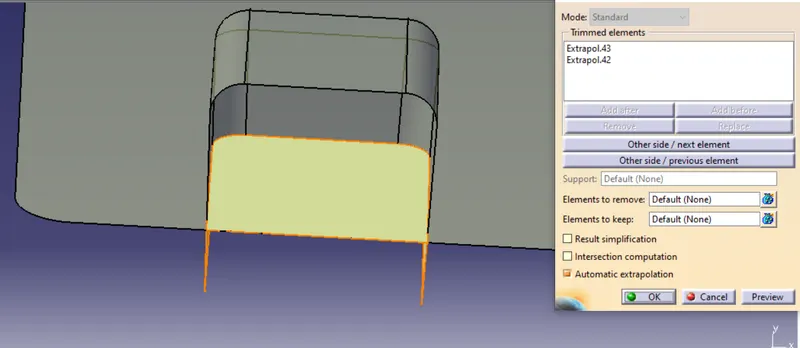
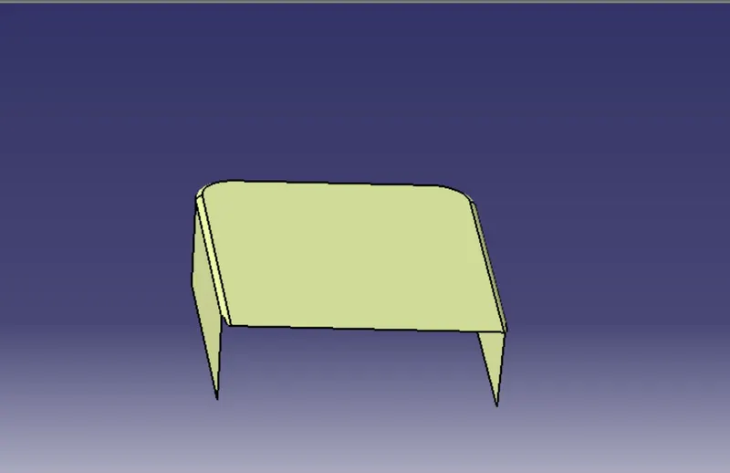
23. Go to the part design and split it with the model and After that we will fillet the entire model of the dog house and add it to the main body.
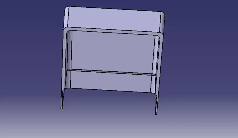
24. Now, Later we mount the screw boss on the dog house by translating it.
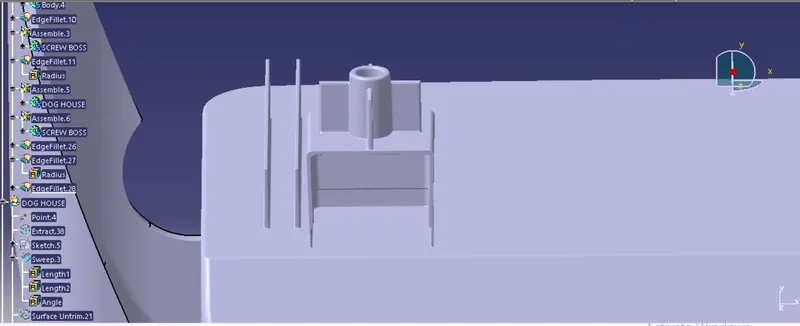
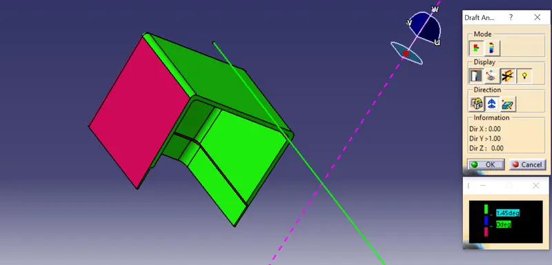
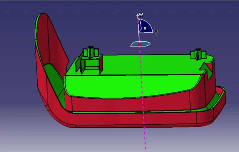
DRAFT ANALYSIS OF THE DOG HOUSE AND MAIN MODEL:-
Following the steps are followed to do the draft analysis:-
1. Go to Insert>Analysis>Feature Draft analysis.
2. Choose the compass and place it along the main tooling axis first.
3. Lock it and click on the component .we will see color on the component.
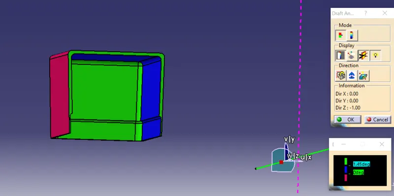
4. As we cannot run two draft analysis on the same component, use the compass for the side core tooling axis.
To Uderstand the color code first we have to know the colour code scale.to the three different value of. for Example if we give 0.5deg value in green ,0 deg in blue and last negative color as Red.
1. The Surface which are in green color means that the draft value it has is more than 0.5deg and it will not create problem.
2. The surface in blue have the draft value between 0deg to 0.5 deg.
3. The surface in red have the draft value in Negative.
Now if we are getting side face in red color for the main Tooling axis.This result is correct as we know that those face will not clear axis. But if we expected any outer surface in green but it is either in blue or red then either we have to give draft and modify our tooling axis.
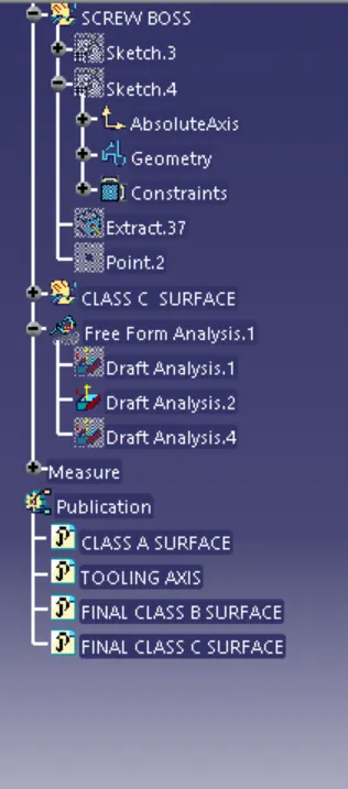
TREE STRUCTURE :-
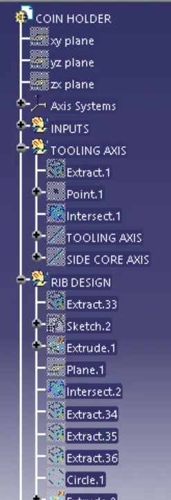
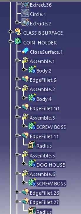
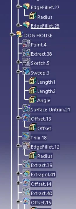
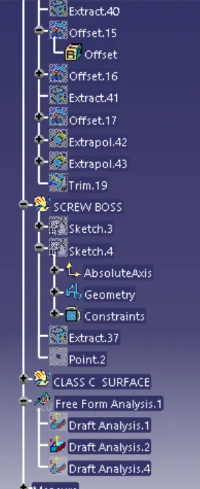
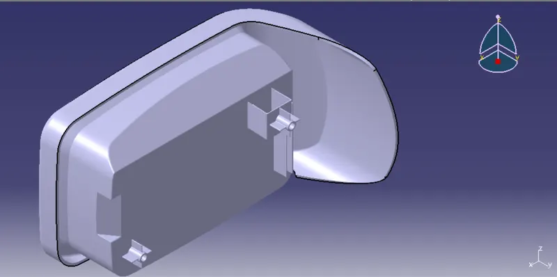
The completed design in various orientations of Model (Isometric, Front, Side, and Top View):-
Isometric View:- Front View:-
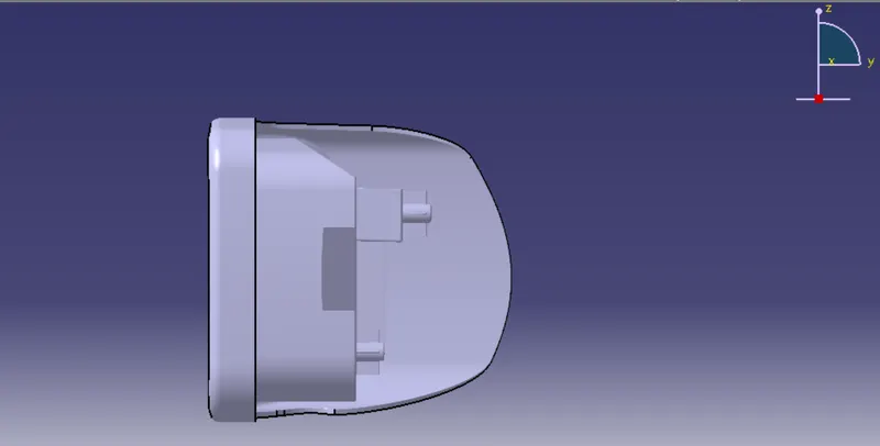
Side View:- Top View:-