Week -2
TITLE:- Challenge for Week-02
AIM:- To make a simulink model of Doorbell Using Solenoid Block and To create a simulink model of Fan Condition using a thermistor to sense the temperature oa a heater and turn on or turn off the fan.
OBJECTIVE:-
- To create simulink model of Doorbell Using Solenoid Block and To create a situation for the switch is Closed for 2 second.
- To create simulink model of fan as per given following condition-
- Temperature source:-20 °C from 0 to 10 seconds, 27 °C from 10 to 30 seconds, 23 °C from 30 to 50 seconds.
- Fan conditions: ON if the temperature above 25 °C, OFF otherwise.
Given Doorbell Figure:-
INTRODUCTION:-
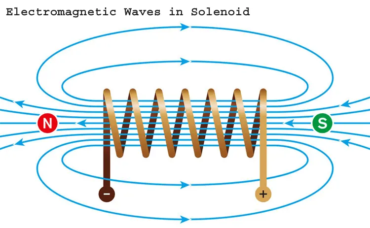
Defination Of Solenoid:- A solenoid is a genetic term for a coil of wire used as an electromagnet. it also refers to any device that convert electrical energy to mechanical energy using solenoid. a coil of many circuler turm of insulated copper wire wrapped closely in the shape of cylinder is called solenoide.
Application of Solenoide:-
1. It is used in particuler type of door locking system.
2. It is used in many different appliances and product like Doorbell, computer, printer etc.
Defination of Thermistor:- A thermistor is a type of resistor used to measure temperature changes on the change in its resistance with changing temperature. Thersmistor is a combination of the word thermal and resistor.
MODEL STUDY:- 01
Create model for Doorbell :-
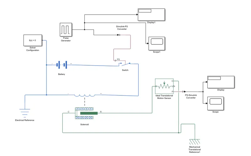
Used block name is in doorbell model as below follwing:-
- Solenoide Block
- Pulse Generator
- Battery Block
- Solver Configuration Block
- Switch
- Electrical Referance
- Ideal Translation Motion Sensor.
- Simulink-PS Converter
- PS-Simulink Converter
- Mechanical translational Referance
- Display
- Scope
Explain of block used:-
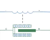
1. Solenoide Block:- A solenoide Block is an electrically controlled valve. which is an electric coil with a movable ferromagnetic core in its center. It block is used to convert electrical energy into mechanical energy.Parameter is in terms of two points [X1,F1] and [X2,F2] and Rated voltage denoted by 'Vdc' , Rated current denoted by 'Idc'
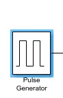
2. Pulse Generator Block:- It Block is used to generate a voltages pulse to the switch block.parameters used in this block are pulse type based on Time, Time(t) based on use simulation time, Amplitude, Period in second,Pulse Width, Phase delay in second.
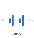
3.Battery Block:- This block models a battery. It generate a voltage source which help in supply electrical power to solenoide block.
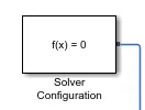
4. Solver Configuration Block:- This block used for specifies the solver paramerter that your model needs before yopu can begin simulation.
5.Switch:- The block represents a switch controlled by an external physical signal. If the external physical signal PS is greater than the threshold, then the switch is closed, otherwise the switch is open.

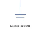
6.Electrical Referance:- The Electrical Referance block repesent an electrical ground. electrical port of the block are directly connected to ground.
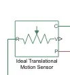
7. Ideal Translation Motion Sensor:- this block is used tio detect weather there any linear motion in the solenoide block during simulation. Connection R and C are Mechanical translational conserving block and connection V and P are physical signal output ports for velovity and position.
8. Simulink-PS Converter:- This block is used to Converts the Simulink input signal to a Physical Signal.

9. PS-Simulink Converter:- This block is used to Converts the input Physical Signal to a Simulink output signal.

10. Mechanical translational Referance:- This block represent a reference point. the translational port are connected to ground.

11. Display:- This block is connected to a single our model and Show its value during simulation.
12. Scope:- This block is used to create plot and record the result.

Procedure of Connection:-
- Fistly we have create file name give as Doorbell and save file in current directory.
- First we have create model and insert a Solenoide block into our model.
- We connected( Electrical Connection) of solenoide block terminal to the Battery block terminal. which bypass through a switch connect.
- After we use Pulse Generator Block it connected to the switch. Simulink-PS convertor is connected between Pulse generator and Switch . which hepl in creating the required input condition i.e Circuit should be closed for 2 second using block a Simulink-PS Convertor.
- We have use Solver Configuration it is connect to before battery terminal corner.
- An Electrical reference is connected to the negative terminal of electrical circuit.
- We have connect Scope Block and Display block After Pulse generator Block Used.
- After we have Connection for Mechanical System. An Ideal Translational Motion Sensor is inserted into the model and the port R of Ideal Translation Motion Sensor connect to the port R of Solenoide Block and the port C of Ideal Translation Motion Sensor connect to the port C of Solenoide Block.
- Referance terminal(on Port C) Solenoide and Ideal Translation motion sensoris connected to the machanical reference.
- After we hace used PS-Simulink convertor it connected after Motion Sensor.
- A Scope and Display Block is connected to the output of Ideal Translational Motion Sensor by using the PS-Simulink Convertor.
The input Parameter given Pulse Generator Block:-
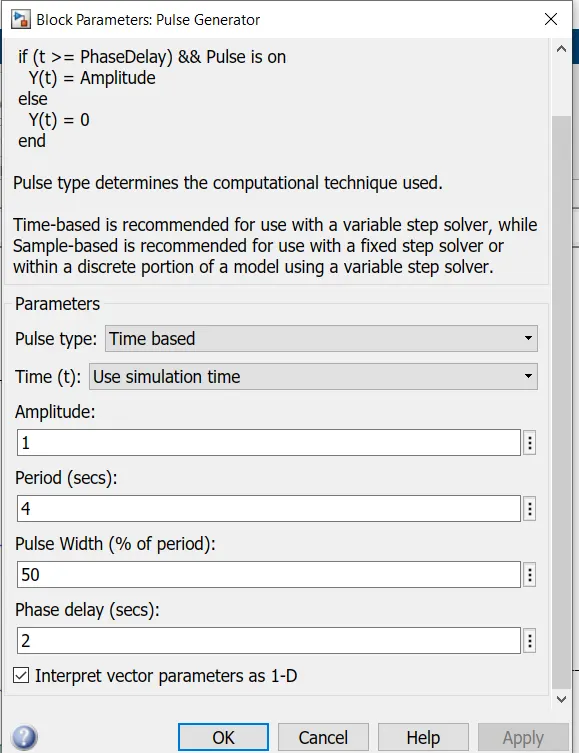
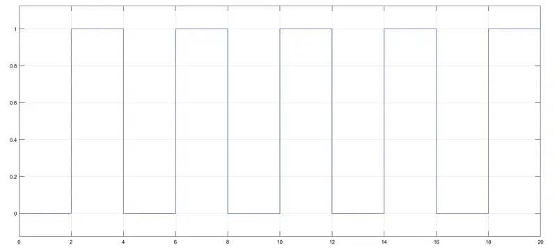
Above shown in figure various parameters :- the pulse generator it is specifed that I have give Amplitude:- 1, Period in second:- 4, Pulse Width(% of Period):- 50 and Phase Delay in Second:- 2.
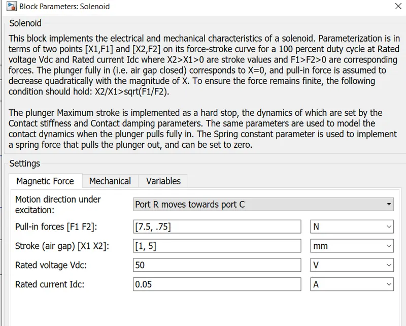
Above shown in figure various parameters :- Setting in magnetic force F1 and F2 are force corresponding ro X1 and X2 is a stroke. reted voltage is the voltage required to power uo the solenoid.
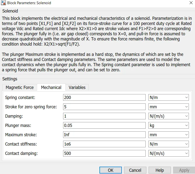
Above shown in figure various Mechanical parameters :- Plunger mass, Spring stiffness, and damping.
Output Graph for Pulse Generator:-
Observation of above graph:-
The phase delay is set to 2 second, untill 2 second the pulse will be zero.After the 2 second the pulse rised from 0 to 1 as amplitude set to 1. we have give Cycle time is 4 Second where pulse width is generated for 50% of the total cycle time 2 second. The cycle comlete the periode 4 second.in this way cycle continues.
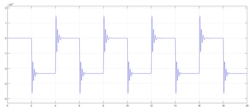
Output Graph for Ideal Translational Motion Sensor :-
Observation of above graph:-
We can seen from the above graph, the motion is getting Generate for 2 second and in graph see time for 0 to 2 second is null and from 2 to 4 second it gives oscillation.
MODEL STUDY:- 02
Create model for Given of fan as per following condition- :-
Temperature source:-20 °C from 0 to 10 seconds, 27 °C from 10 to 30 seconds, 23 °C from 30 to 50 seconds.
Fan conditions: ON if the temperature above 25 °C, OFF otherwise.
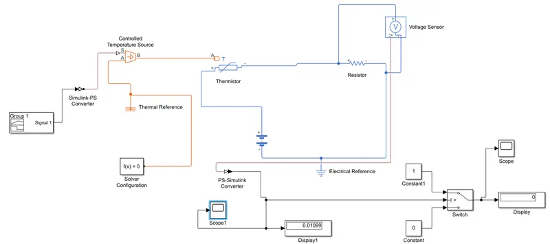
Used block name is in Fan model as below follwing:-
- Signal Builder Block
- Conttrolled Temperature Source
- Thermal Referance
- Thermistor Block
- Resistor Block
- Voltage Sensor
- Constant Block
- Switch Block
Explain of block used:-
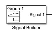
1. Signal Builder Block:- This block used for To generate the temperature condition a signal builder is used with a controlled temperature source. The signal builder generate a simulink signal which varies with time as defined.
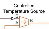
2. Conttrolled Temperature Source:- This block represents an ideal energy source in a thermal network that can maintain a controlled temperature difference regardless of the heat flow rate.
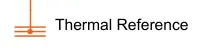
3. Thermal reference:- This block represents a reference point in a thermal network.
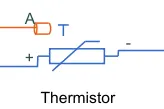
4. Thermistor Block:- Temperature sensing element negative temperature coefficient thermistor using B- parameter equate.
5. Resistor Block:- A resistor is a two terminal (Positive and Negative) electrical component. Resistor are used to reduce the current flow. The voltage-current (V-I) relationship for a linear resistor is V=I*R, where R is the constant resistance in ohms.

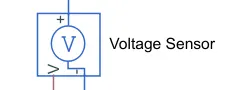
6. Voltage Sensor:- The block represents an ideal voltage sensor, that is, a device that converts voltage measured between any electrical connections into a physical signal proportional to the voltage.
7. Constant Block:- Output the constant specified by the 'Constant value' parameter.

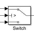
8. Switch Block:- The switch block passed through the 1st input or the 3rd input signal basewd on the value of second input. The 1st and 3rd inputs are data input. The 2nd input is a control input. Specified the condition under which the block passes the 1st input by using the criteria for passing first inputs and Threshold parameters.
Procedure of Connection:-
- First we have create a file name given as Thermistor fan model and save file in current directory.
- we have insert a signal builder into our model.
- The Signal Builder terminal is connected to the simulink-PS converter and the another terminal of simulink-PS converter is connected to the port S of controlled temperature source.
- The controlled temperature source of port A connected to Thermal Referance and Solver Configuration is to connected on above thermal referance line.
- After we have connected B port of controlled temperature source to the port A of Thermistor.
- We have used Thermistor Block there are two terminal name as +ve and -ve terminal. the +ve terminal is connected to the +ve terminal of Battery and -ve therminal of Thermistor is connecte to the -ve terminal of Battery. which bypass through a switch connect.
- Next we have insert the Voltage Sensor block into the model , The +ve terminal of voltage sensor is connected to the +ve terminal of Resistor and the -ve terminal of voltage sensor is connected to the -ve terminal of Resistor.
- The Electrical Referance is connected between Battery & Resistor.
- After We have connected V port of Valtage Sensor to the PS-simulink Convertor.
- We have insert the Switch block into a model. Switch block are 3 ports the 1st port is connected to 1st constant Block and 2nd port is connected to 2nd constant block and 3rd port is connected to the PS-Simulink Convertor.
- After we have connect one display and one Scope to the between PS-Simulink Converto& Switch.
- The one Display and one Scope is connected to the 1st port of Switch.
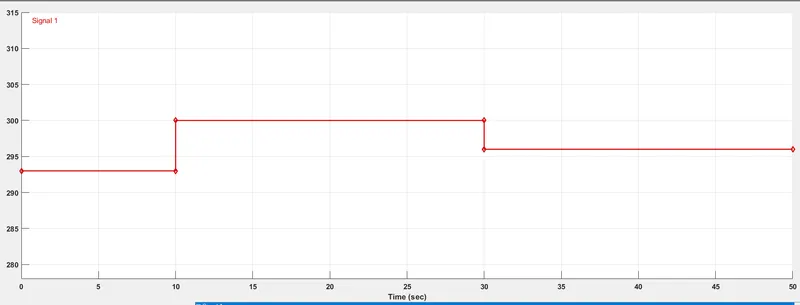
The Above shown in graph :- The above is the signal builder plot. the temperature sources are set to the following condition:-
- For time set 0 to 10 second. the temperature is 263K.
- For time set 10 to 30 second. the temperature is 300K.
- For time set 30 to 50 second. the temperature is 296K.
Output for Fan Condition:-
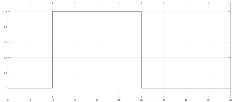
Observation:- We can seen in this plot the Switch is 'ON' when the temperature is above 25 degree C, Because this is where the temperature is above 27 degree C (300K).
The Fan Condition is ON if the temperature above 25 °C, OFF otherwise.
CONCLUSION:-
- To create of Doorbell is done using Solenoide Block and Create a situation where the switch is closed for 2 seconds and then released. Observe the physical movement of the plunger.
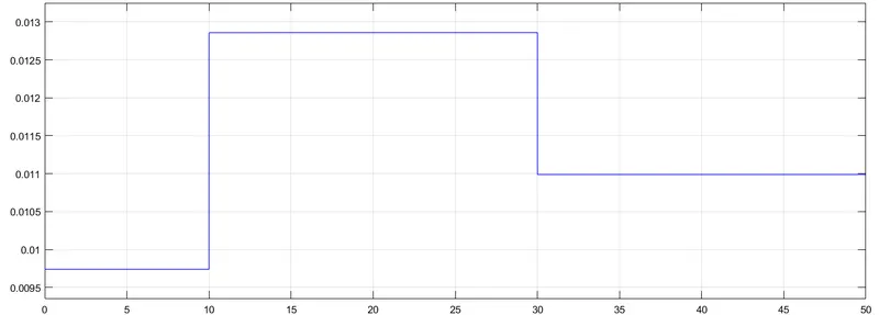
- To Create model for Fan Condition the Switch is 'ON' When the temperture is above 25degree C. Which is an interval of 10 to 30 second. when the temperature below 25degree C the Switch is 'OFF' Condition.
THANK YOU!