Week 9 - Project 1 - Door Applique Design with Engineering Features
AIM:- To Create a door applique design from Class A- Surface and To Create enginnering Features to fit the Component in the main surafece and Create the Heat Stakes and the locators considering the design rules mentioned in the challenges for the door applique.
OBJECTIVE:-
- TO Create Class B Surface and Class C Surface from given Class A surface.
- The Tooling axis for the given Class A-Surface should be created to meet requirement of the draft angle.
- Create the Heat Stakes and Locators considering the design rules.
- To perform the Draft Analysis on the model.
THEORY:-
Heat Staking:-
Heat Staking is a pulsed heat process to join two or more parts out of which one at least is made of plastics. The process is to deform the plastics material using heat force at a set process time. The bond is made by partially de-forming the plastics parts in order to fix the other.
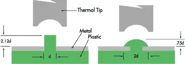
Heat Staking makes it easy to bond metak to plastics and is commonly used in high volume and low cost application such as Automotives and consumer appliances.
In manufacturing of thermoplastics component it is often necessary to join the thermoplastics to a part of a dissimilar material.weather it can be a metal,dissimilar material or other materials. Thermal staking is an assembly method that use the controlled melting and reformimg of a plasticstude or boss to capture or lock another plastics or a metal component of an assemblying place.
Advantages of Heat Stakes:-
- Similar and Dissimilar material may be joined: metal to metal, plastics to plastics, metal to plastics.
- Local heating resulting in no damages to surrounding materials.
- Accurate control operating within a small process window.
- No mechanical Vibration.
- Processing of glass filled materials.
4 and 2 Way Locators:-
- Locators are used to locate a job or a component to rest its degrees of freedom using the 3-2-1 Principle which is arresting of 3 DOFs first then 2 DOFs and DOF in a sequence.
- A 4 Way locator will look like a "+" and a 2 way locator will look like a "-".
- Both these locator used the same rib Design Rules and principle.
- These Locator are placed on the B side of the component and must have same height with respect to the B Surface.
Fixture Design Rules:-
- For a fixture designer, the major portion of design time is spent deciding how to locate the workpiece in the fixture.
- You know that any freebody has a total of Twelve degrees of freedom as below:-
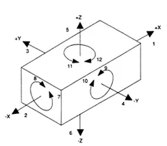
6 Translation Degree Of Freedom, +X,-X,+Y,-Y,+Z,-Z.
- Clockwise around X-axis
- Anticlockwise around X-axis
- Clockwise around Y-axis
- Anticlockwise around Y-axis
- Clockwise around Z-axis
- Anticlockwise around Z-axis
You must fix all the 12 Degree of freedom except the three transitional degree of freedom(-X.-Y,-Z). in order to locate the workpice in the fixture.
The Jig and fixture are tools used for holding the workpiece in a correct location for mass production, Various type of fixture are used in the industry. The 3-2-1 Method is the fundamental principle for all type of fixture design.
PROCEDURE:-
Design Check On received Class A Surface:-
1. After receiving the Class A from the Applique Check for the connectivity of the surface on it.
Fig:- Door Appliue
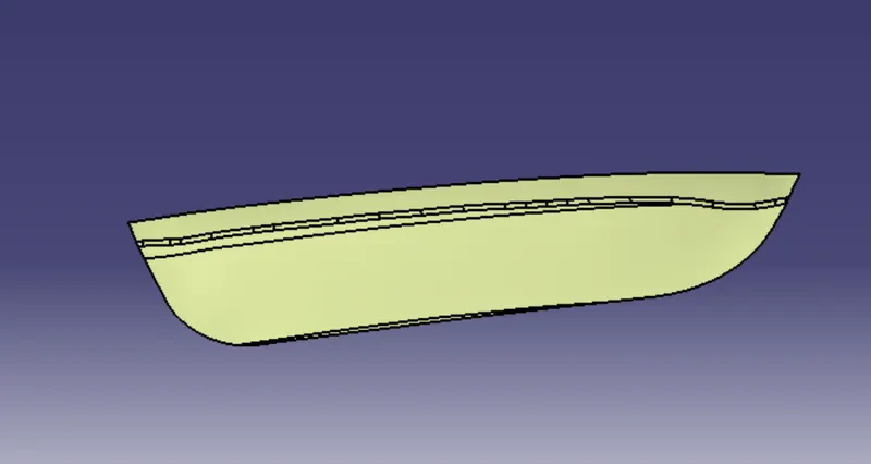
Fig:- Door Attachment
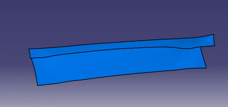
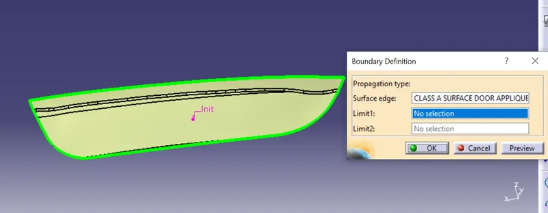
2. Boundary Check Of Door Applique
Creation The Tooling Axis:-
3.Identify faces which can potentially create problem while manufacturing.
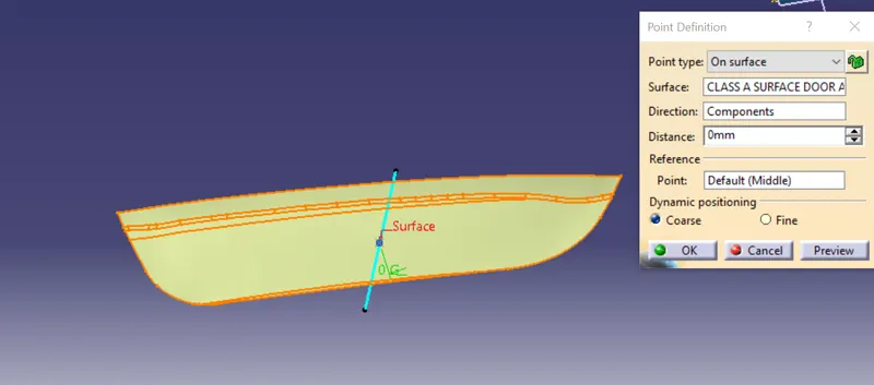
4. Extract the plain surface and Create a point on its center for Tooling Axis Creation.
5. In this case Y axis can be a possible Tooling Axis Direction.So the tooling axis is created along Y axis as shown in fig below,
Performing Draft Analysis on Class A Surface:-
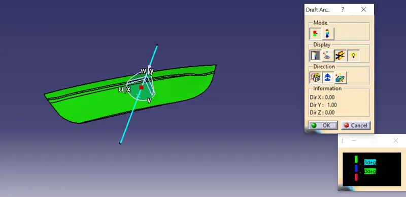
- Go to Insert>Analysis>Feature Draft Analysis and Move the compass to the Tooling axis.
- Change the View Mode Customization to Material Mode.
- Change the Range to 2.9 degree.
- adjust the compass on Tooling Axis.
Creation Class B Surface :-
6. Extract the relevant surface from the Class A Surface while excludes the fillets.
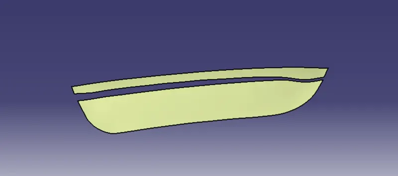
7. Here the selected faces consist of 2 wall.
8. Extract of these surface is shown in the below
9. Use Untrim Command to Untrim the Exracted surface and Create natural extend.
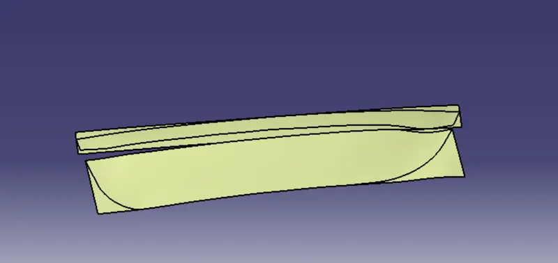
10.Extrapolate the untrimmed surface so that they intersect clealy and pass way forward than the Class A Surface which will help in its trimming operation.
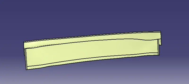
11. Trim the extract surface to obtain similar extended surface as in Class A Surface. The surface obtained after trim is shown in below
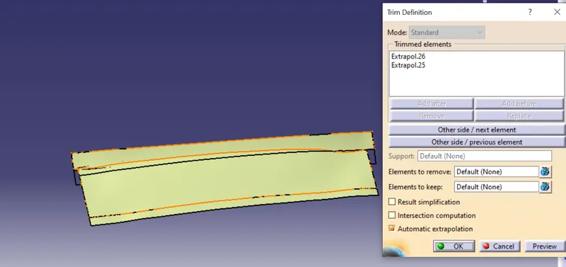
12. Offset the trimmed surface to the value of required Thickness of the Part.
13. In this case of Applique the thickness is considered as 2.5mm.
14. The offset face is the part of B Surface.
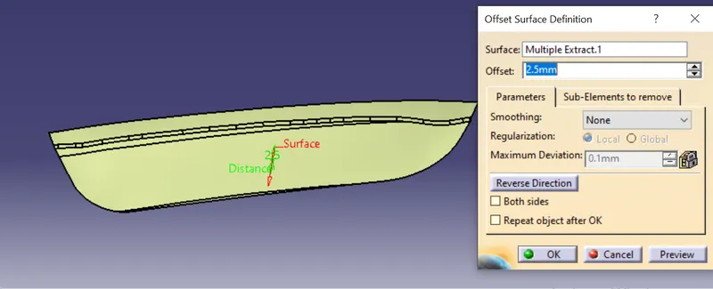
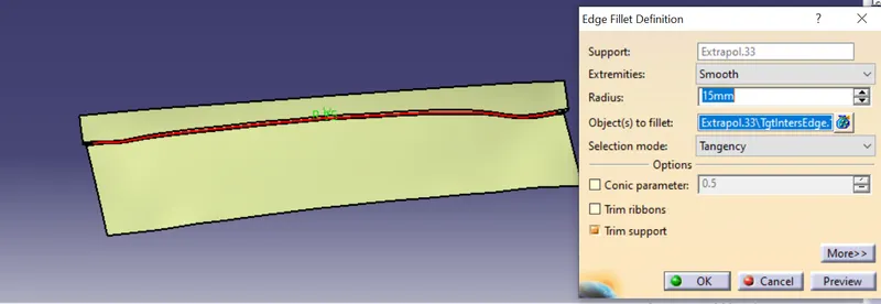
15.Create Fillet while maintaining the part thickness between the class A and Class B Surface
16. The value of fillet is given by the equation (B Surface fillet= A surface Fillet Thickness of the part)
17. The sign + or - must be decided so as to maintan the part thickness which in this case is 2.5mm.
Creation Class C Surface From Class A Surface:-
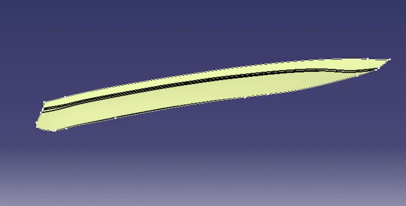
18. Extract the edges of the Class A surface seperately.
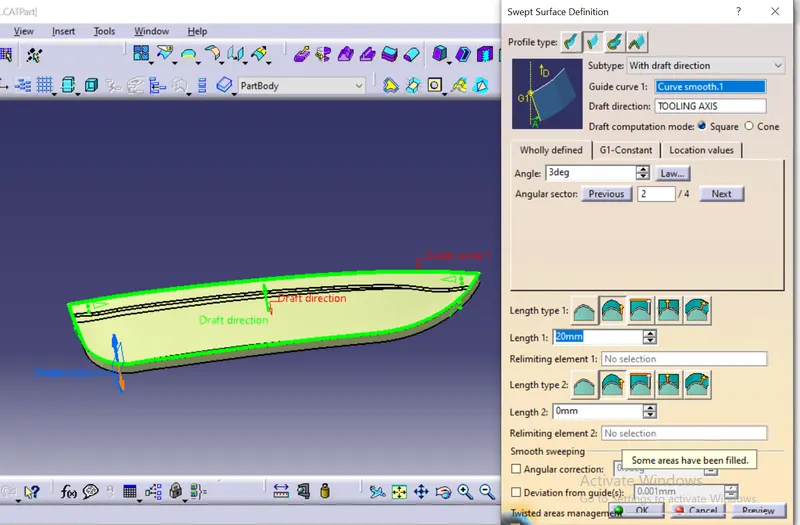
19. Use Sweep Operation to extrude the boundary using the'With Draft Direction' option and selecting the boundary for guide curve and the Tooling Axis as Draft Direction.
20. Use Angle as 3 Degree draft and select outward direction with appropriate lenght say 20mm as shown in fig below.
Final Close Surface Creation:-
21. Join All the Class C Surface along with the Class A surface and Trim it with class B Surface.
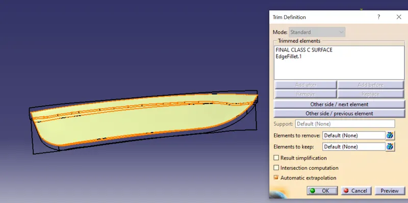
22. To we get final Door Applique Close surface.
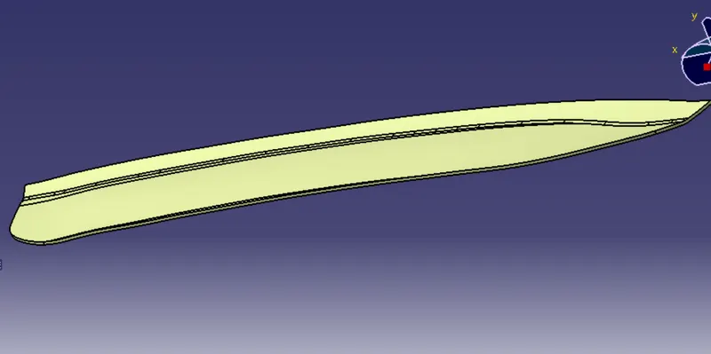
23. Switch to Part Design Workbench and use Close surface option to create a Solid Part From the final Obtained surfaces.
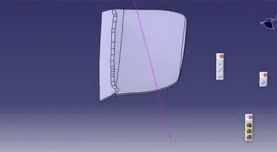
Create Locator and Heat Stakes on B surface:-
24. Create a Plane on the B side.
25. Create a sketch for 4 way locator as shown in below fig
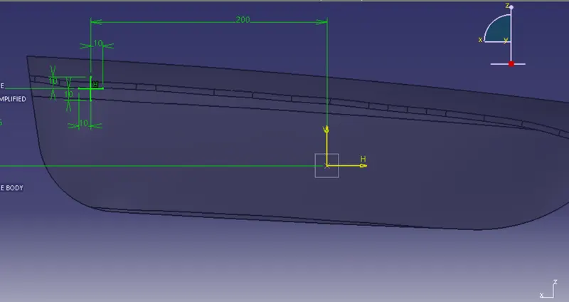
26. Create a sketch for 2 way locator on the same plane as shown in fig
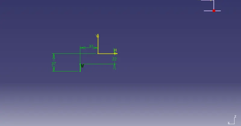
27. Extrude the locators maintaining a thickness of 1.25 mm as per rib design rules.
28. Copy the 4 way locator and Paste special and Translate the 4 way locator to right side so that all the locator are placed equally far away.
29. Make sure the height of the locator is maintained within the rib design rules.

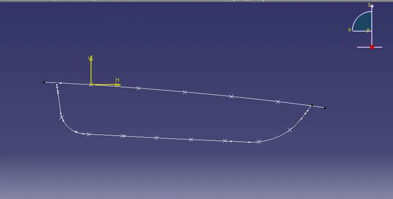
30. Create a sketch of concentric circle for the Heat Stakes.
31. Maintain Wall thickness as per Rib Design rules and extrude the heat stakes at a level which is below the locator by at least 5mm.
32. Ensure that each heat stake is at least 50mm apart from the each other.
33. Give the draft of 0.5 degree to the wall of all the locators and the heat stakes.
34. Use Union trim to keep the required faces with respect to the applique Body.
35. Give the to all th wall and make entry chamfer for the locator.
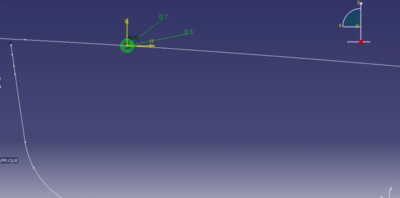
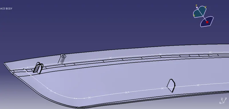
36. We To Get final 4 way ,2 way and Heat Stakes.
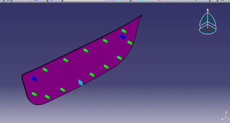
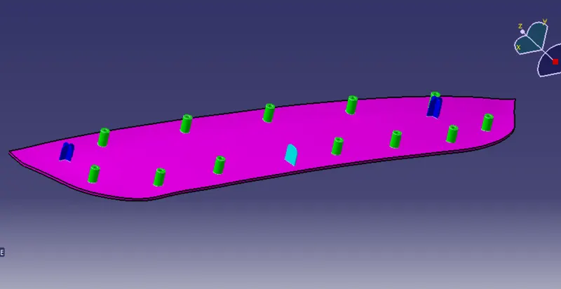
Draft Analysis On Complete Model:-
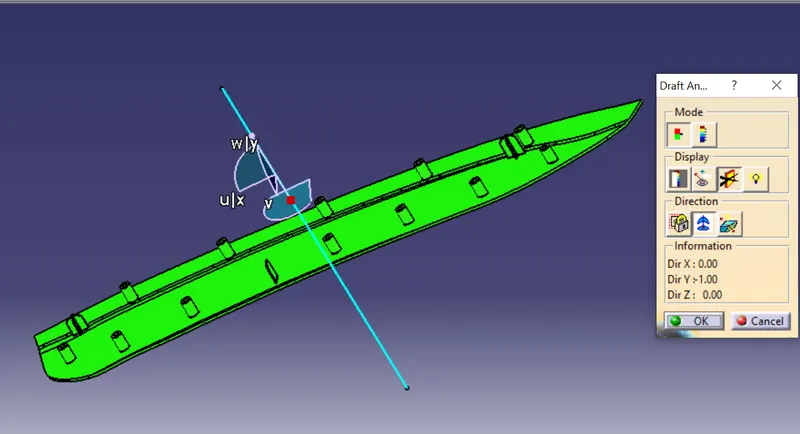
- Go to Insert>Analysis>Feature Draft Analysis and Move the compass to the Tooling axis.
- Change the View Mode Customization to Material Mode.
- Change the Range to 0.48 degree.
- adjust the compass on Tooling Axis.
- The Final Draft Analysis passes on the whole component of Applique along the Tooling axis.
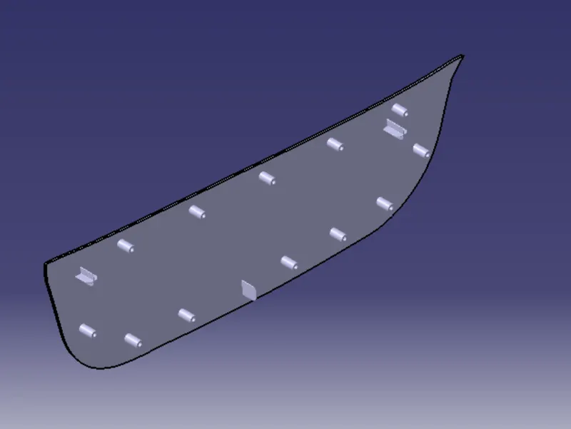
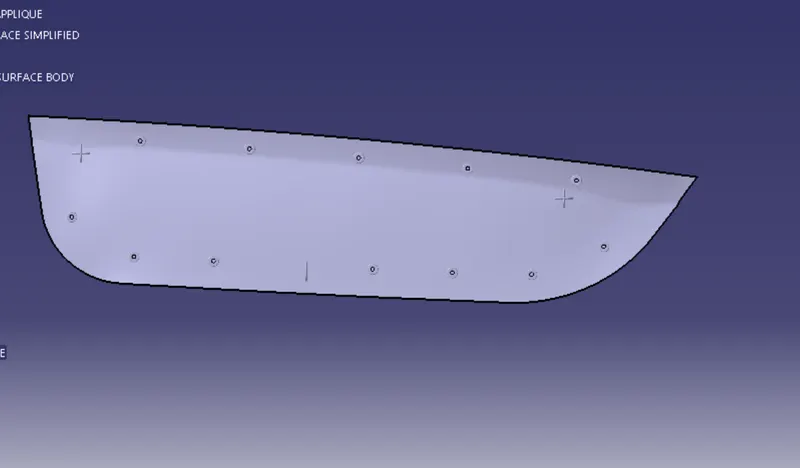
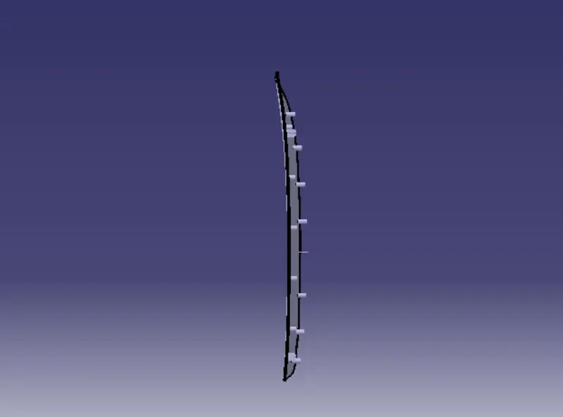
The completed design in various orientations (Isometric, Front, Side, and Top View):-
Isometric View:- Front View:-
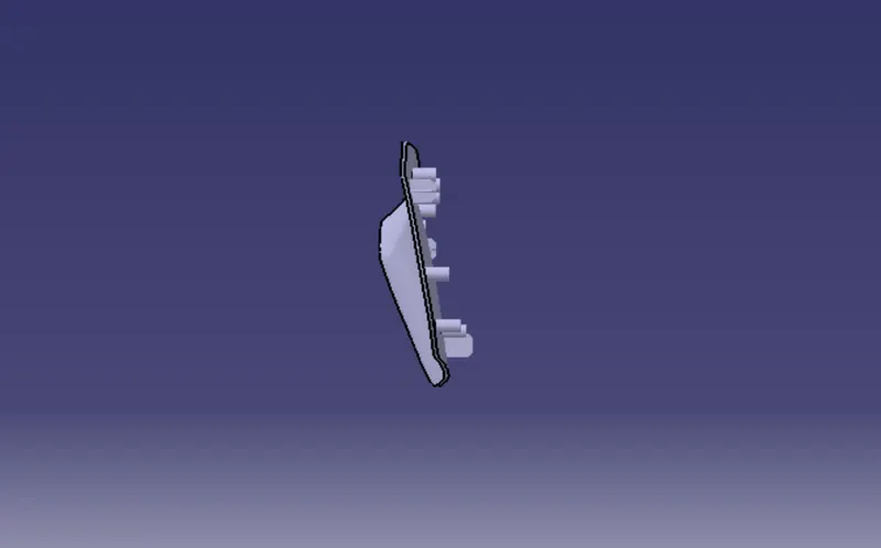
Side View:- Top View:-
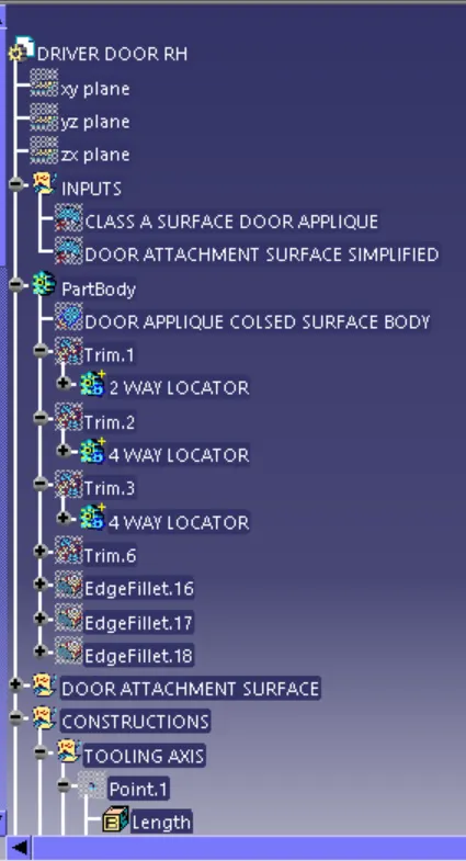
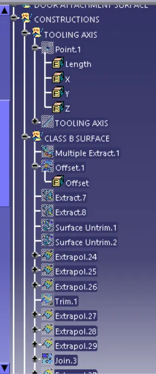
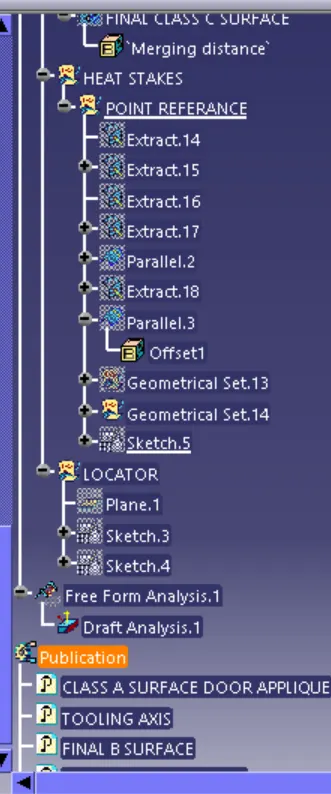
Tree Structure:-
CONCLUSION:- To Create Driver Side RH Door Applique Design with 4 way locator and 2 way locator and Heat Stakes has been compleled by using industrial principle as Rib design rules and also Give Draft angle and Draft analysis on Given Class A Surface and Final Complete Model.