Week 10 - Simulating Combustion of Natural Gas.
Part I
Geometry:
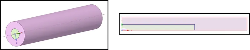
We are provided with a 3-D Model, our focus is to convert this into 2D Model using Split Body
- Start by enabling planes in X-Z & X-Y Planes
NOTE :
The final 2-D plane has to be in X-Y Axis for using axi-symmetrix option in Fluent
- Select Combine > Select all bodies > Ok
- Select Split Body > Choose the target Body
- Choose the target plane 7 reduce it till we get a total 2-D Halved plane
Meshing :
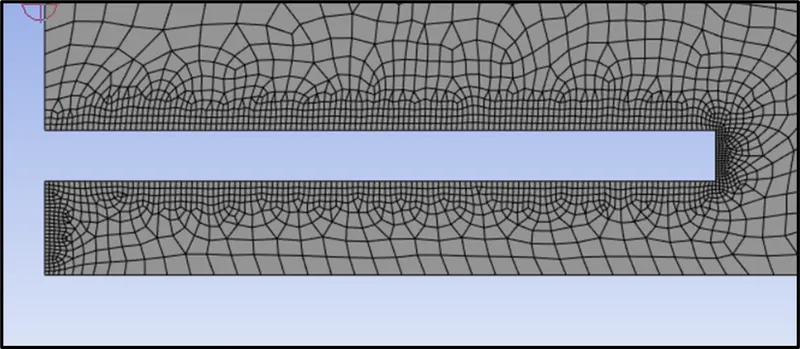
- For quality meshing, lets refine the grids near fuel inlet and gap between fuel and air inlet
- For this, i've utilised sizing feature
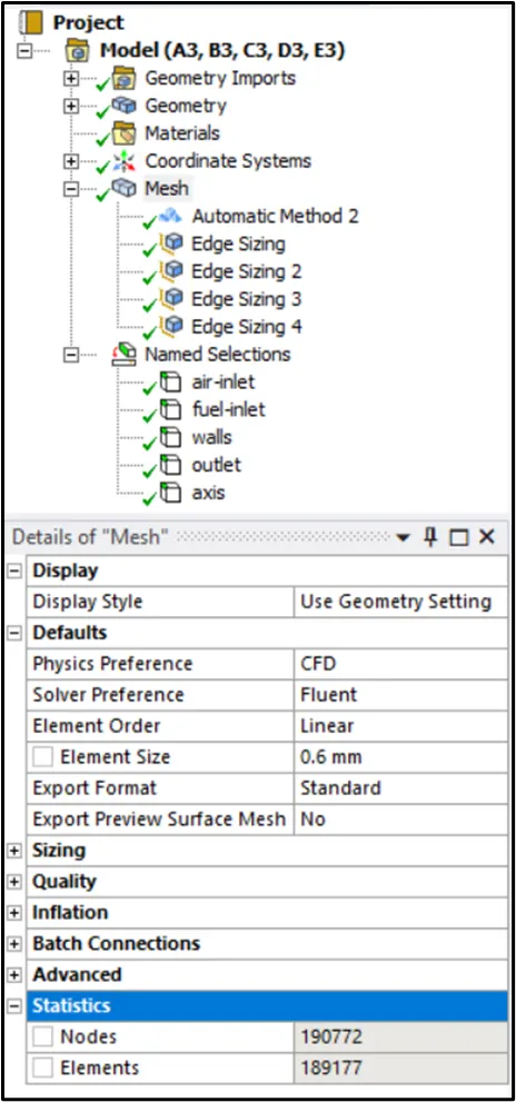
- Mesh method used was Quadrilateral dominant
- Total no of cells are 189177
Solving :
|
Solver Type |
Pressure-Based |
|
Velocity Formulation |
Absolute |
|
2D Space |
Axisymmetric |
|
Time |
Steady State |
|
Viscous Model |
K-epsilon > Standard > Scalable wall Function Energy - On |
|
Models |
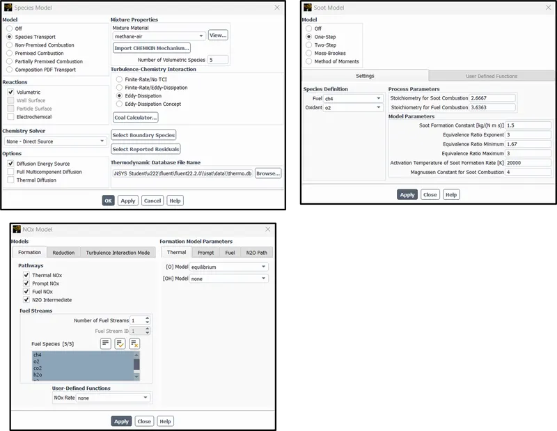
Species > Species Transport - On |
|
Material |
Fluid Type - Air Solid Type - Aluminum Mixture - Methane-air-2step |
|
Boundary Condition |
Air Inlet - Fuel Inlet - Outlet - Pressure outlet (Gauge pressure = 0 Pa) Walls - Stationary wall with no-slip condition Axis - Axisymmetric (x-axis) |
|
Solution Method |
pressure-velocity coupling- COUPLED |
|
Initialization |
Standard Initialization |
Cases-
| Mole Fraction (Cases) | CH4 | H2O |
| Case 1 | 1 | 0 |
| Case 2 | 0.95 | 0.05 |
| Case 3 | 0.9 | 0.1 |
| Case 4 | 0.8 | 0.2 |
| Case 5 | 0.7 | 0.3 |
Results:
Case:1 -
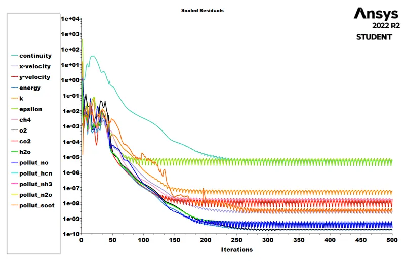
1) Residuals
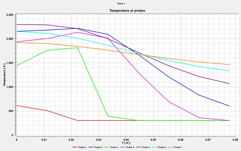
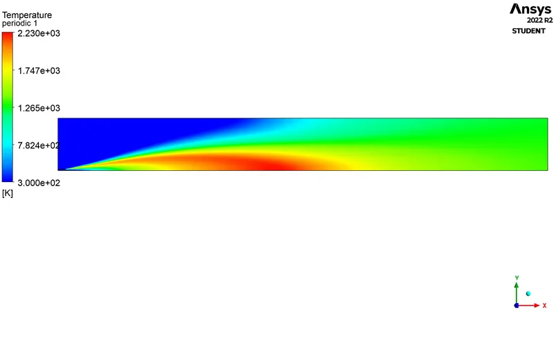
2) Temperature Distribution Profile
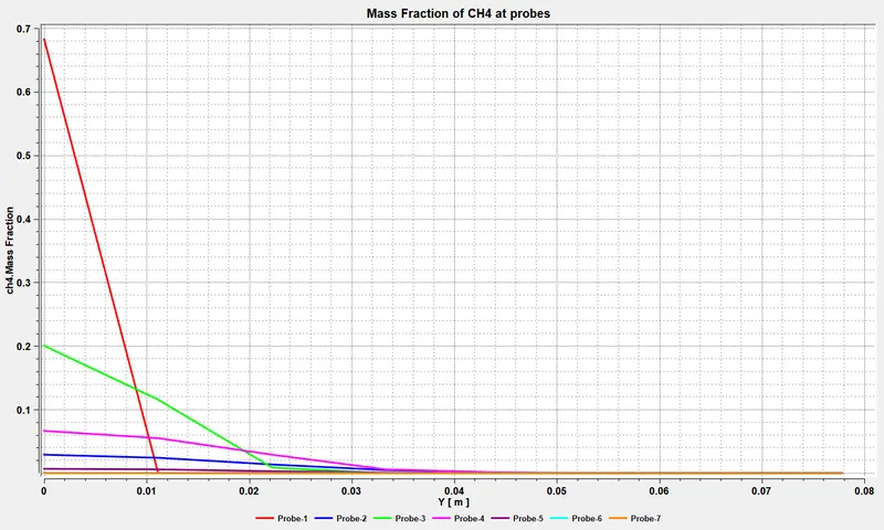
3) Mass Fraction of CH4
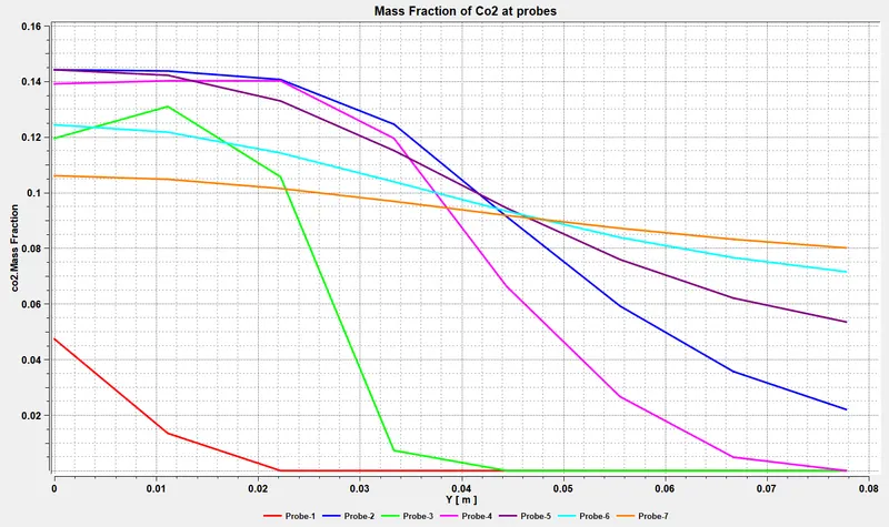
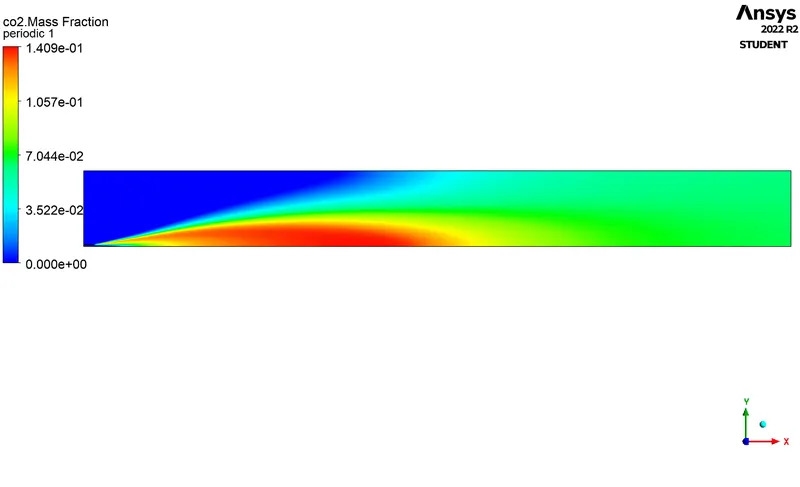
4) Mass Fraction of CO2
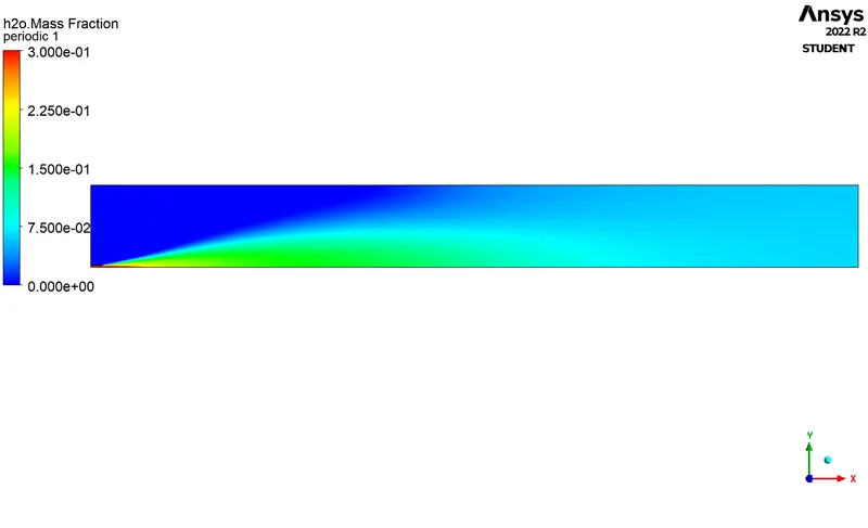
5) Mass Fraction of H20
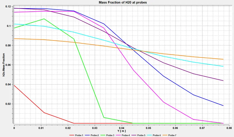
6) Mass Fraction of N2
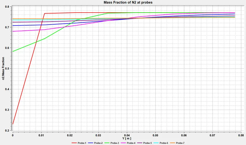
7) Mass Fraction of NOX
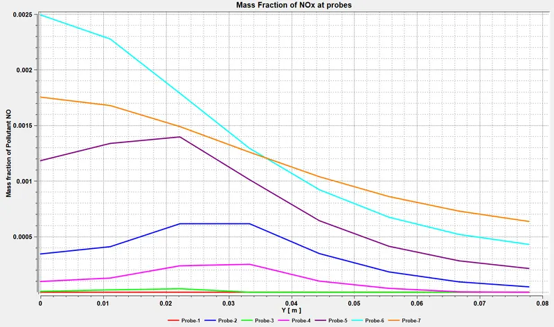
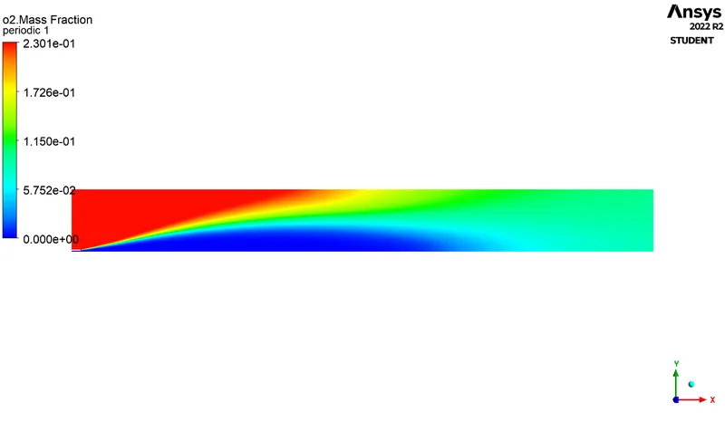
8) Mass Fraction of O2
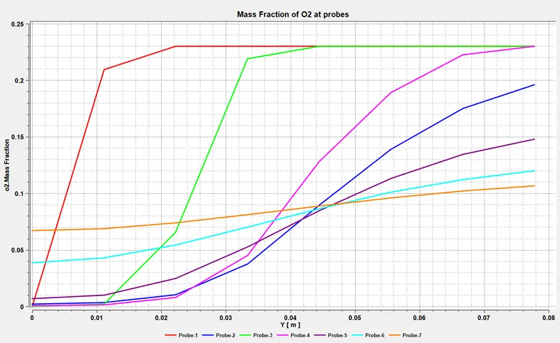
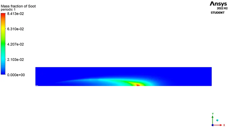
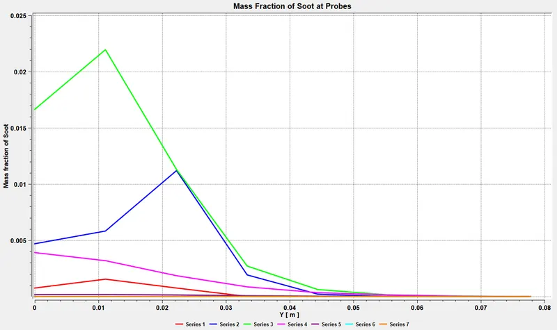
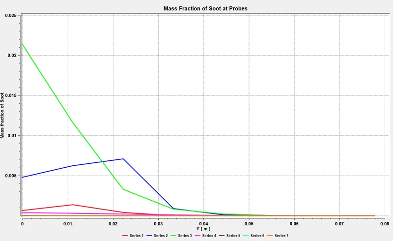
9) Mass Fraction of Soot
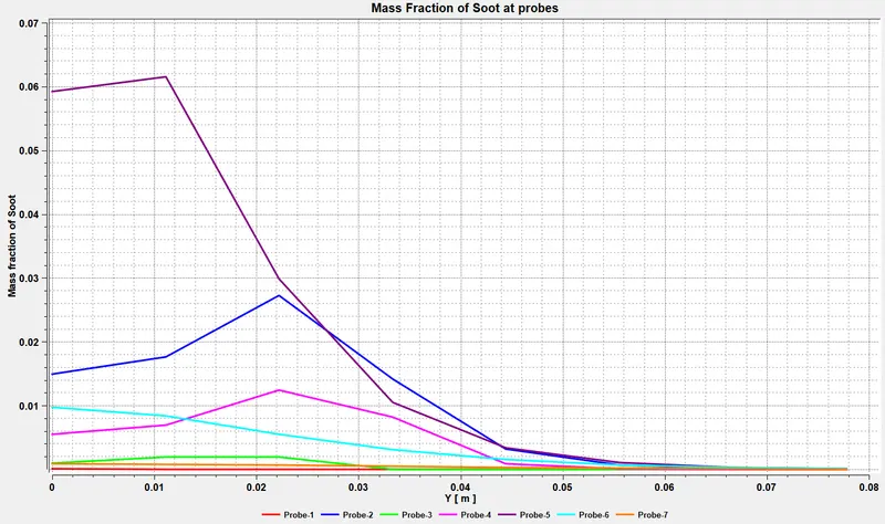
Contours:
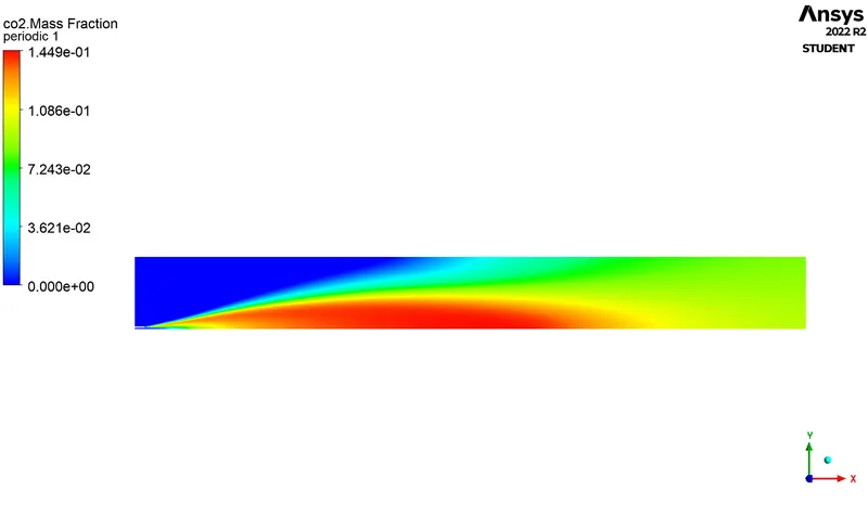
1) CO2 Contour
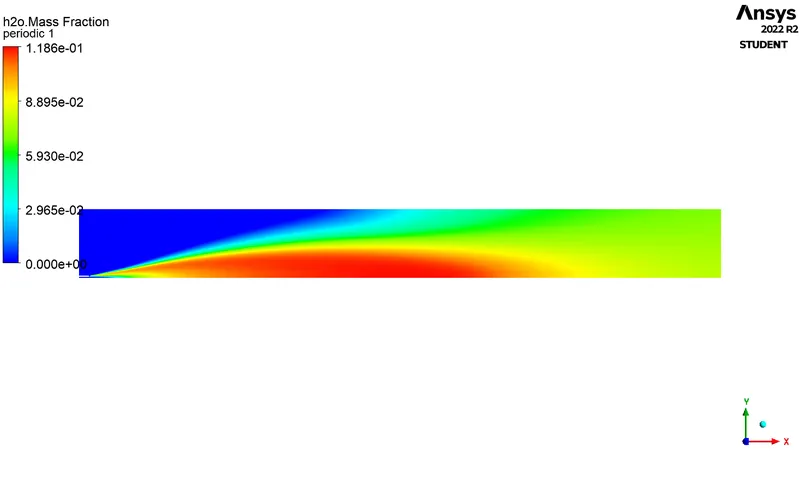
2) H2O Contour
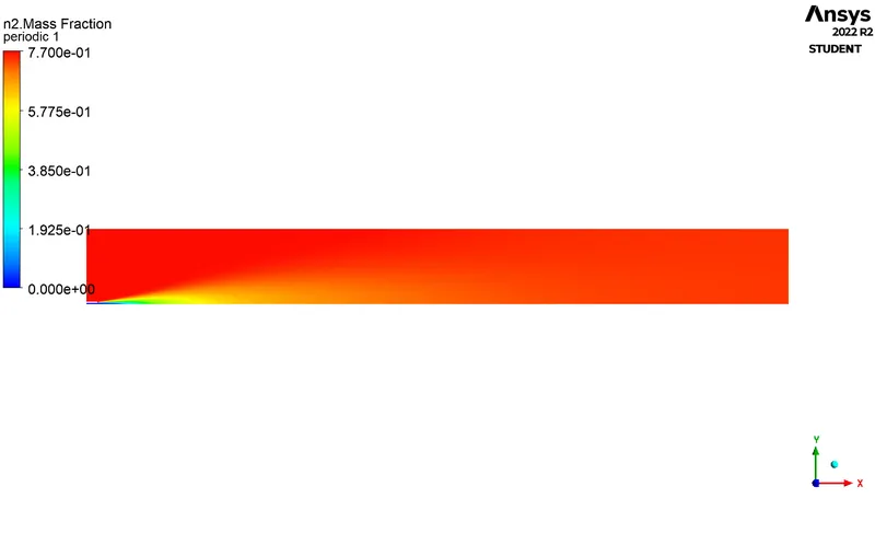
3) N2 Contour
4) O2 Contour
5) NOX Contour

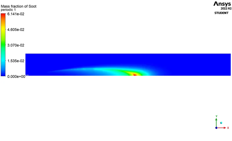
6) Soot Contour
Case:2 -
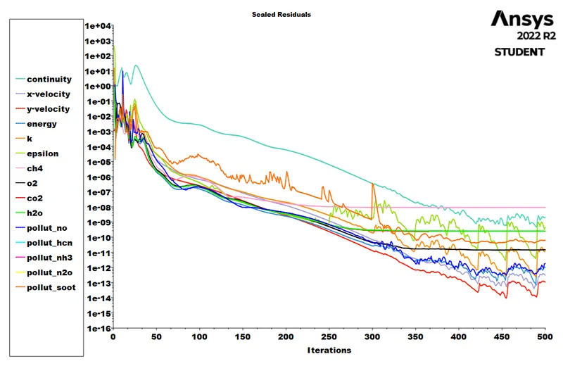
1) Residuals
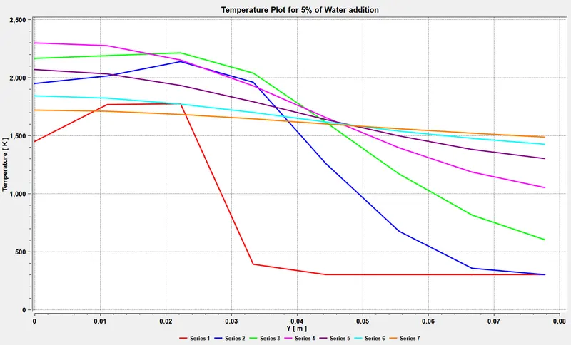
2) Temperature Distrbution Profile
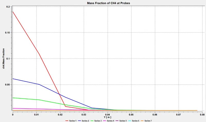
3) Mass Fraction of CH4
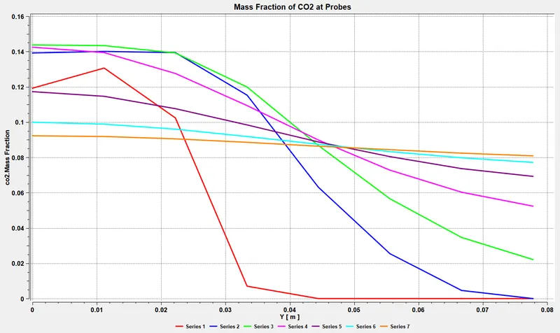
4) Mass Fraction of CO2
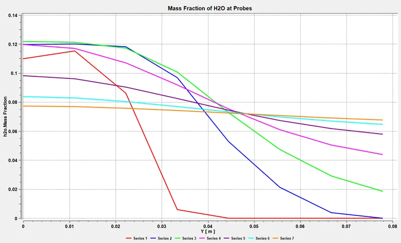
5) Mass Fraction of H20
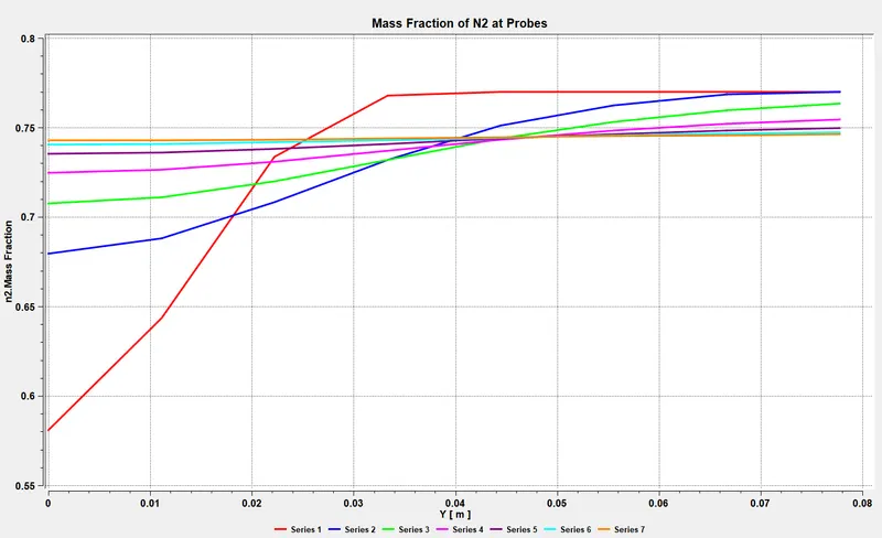
6) Mass Fraction of N2
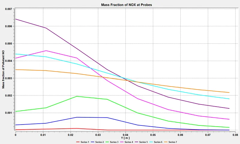
7) Mass Fraction of NOX
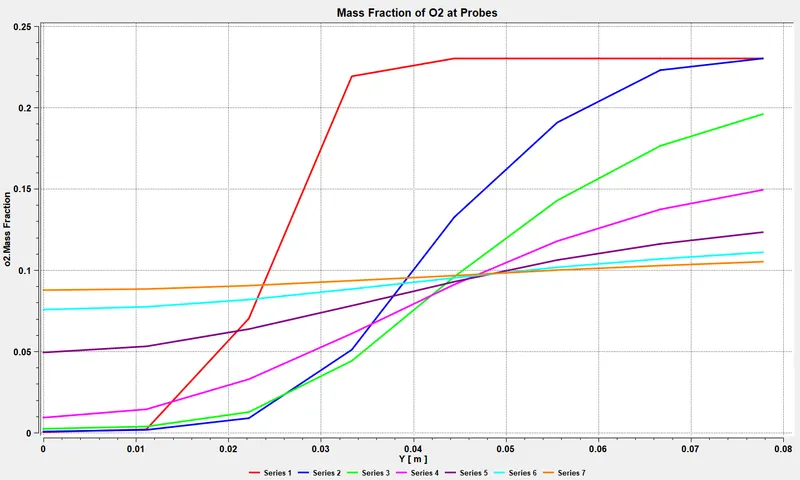
8) Mass Fraction of O2
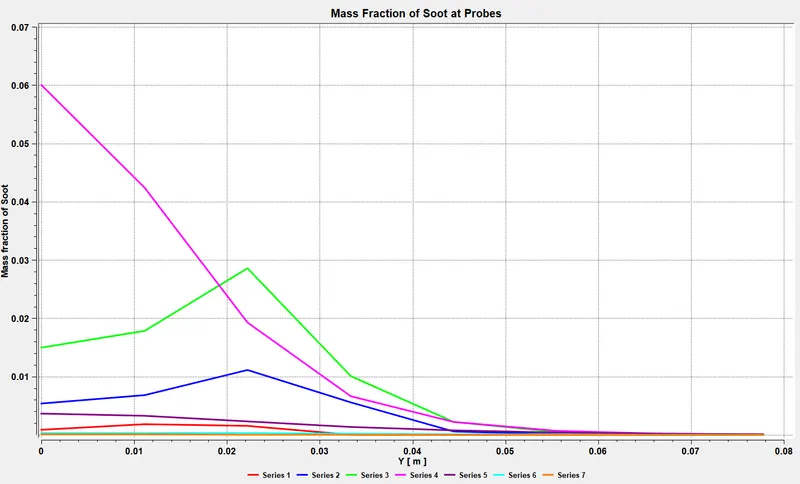
9) Mass Fraction of Soot
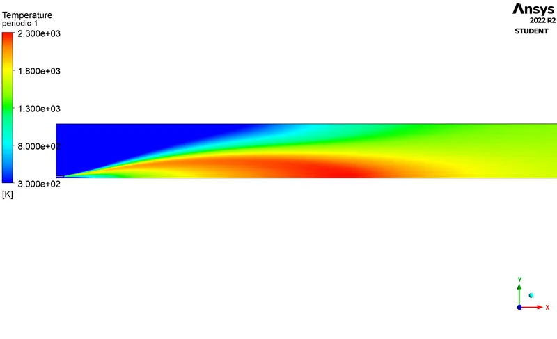
Contours:
Temperature Contour
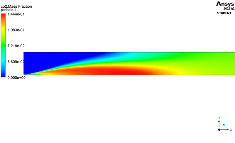
1) CO2 Contour
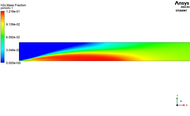
2) H2O Contour
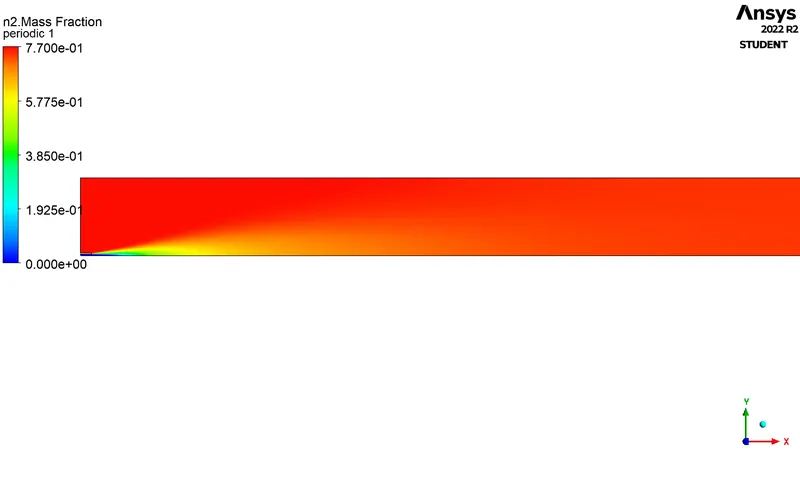
3) N2 Contour
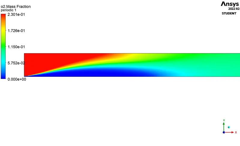
4) O2 Contour
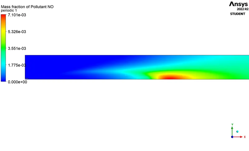
5) NOX Contour
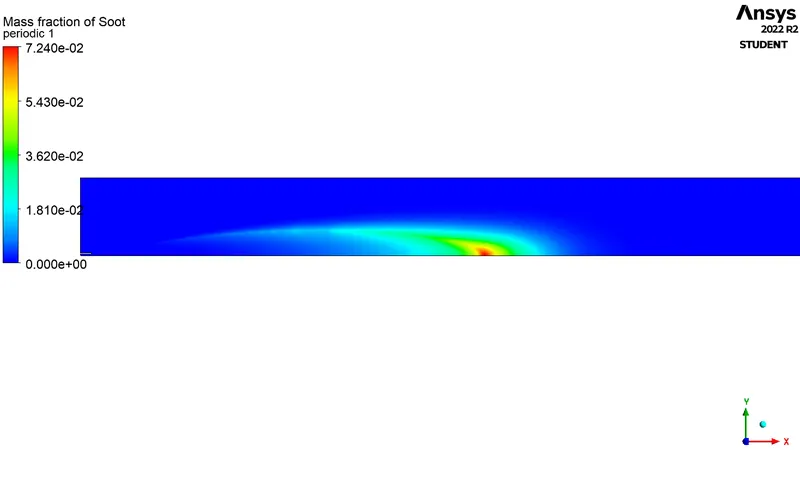
6) Soot Contour
Case:3 -
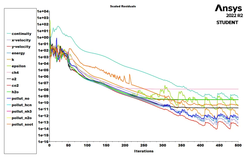
1) Residuals
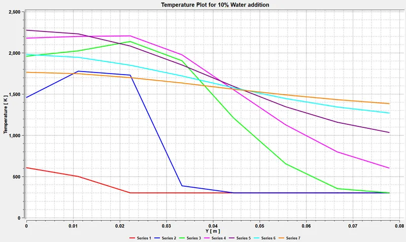
2) Temperature Distrbution Profile
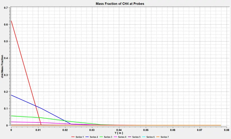
3) Mass Fraction of CH4
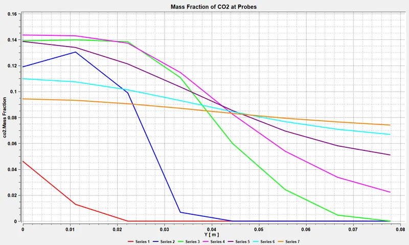
4) Mass Fraction of CO2
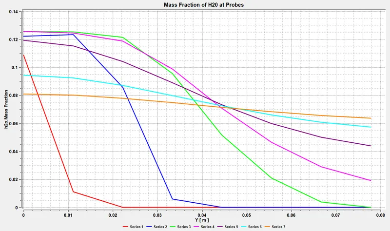
5) Mass Fraction of H20
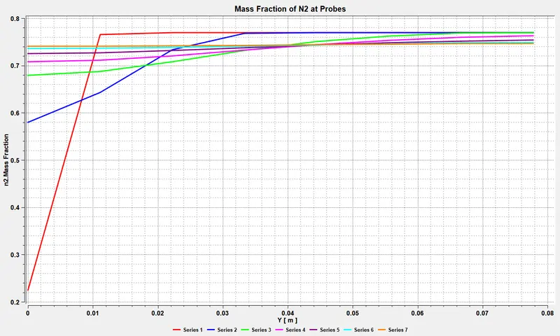
6) Mass Fraction of N2
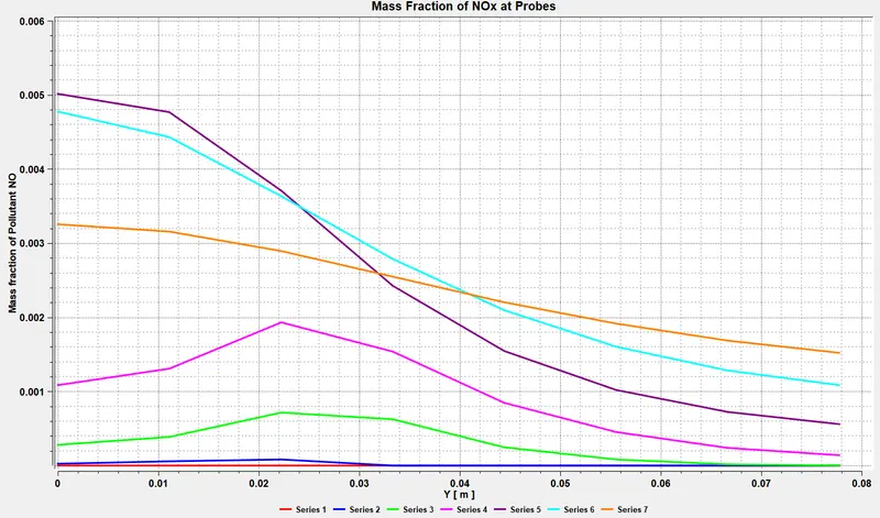
7) Mass Fraction of NOX
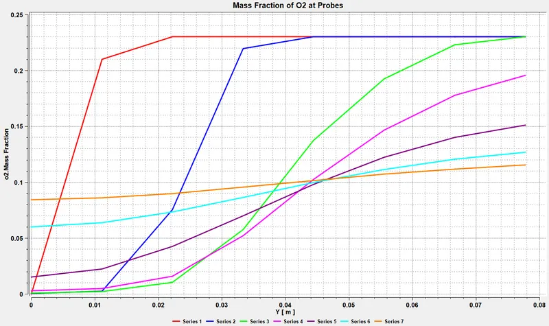
8) Mass Fraction of O2
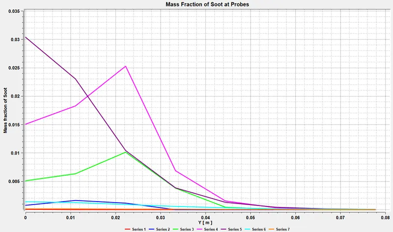
9) Mass Fraction of Soot
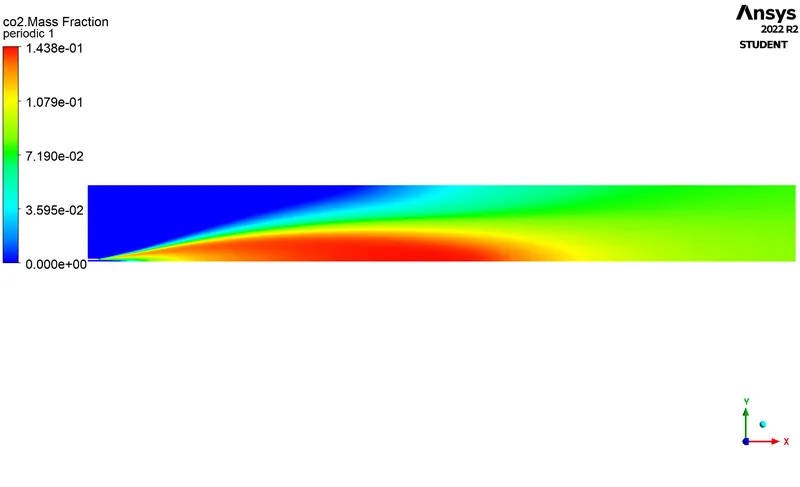
Contours:
1) CO2 Contour
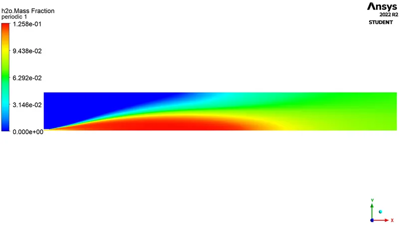
2) H2O Contour
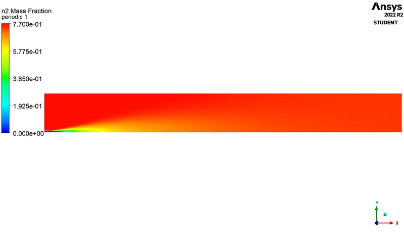
3) N2 Contour
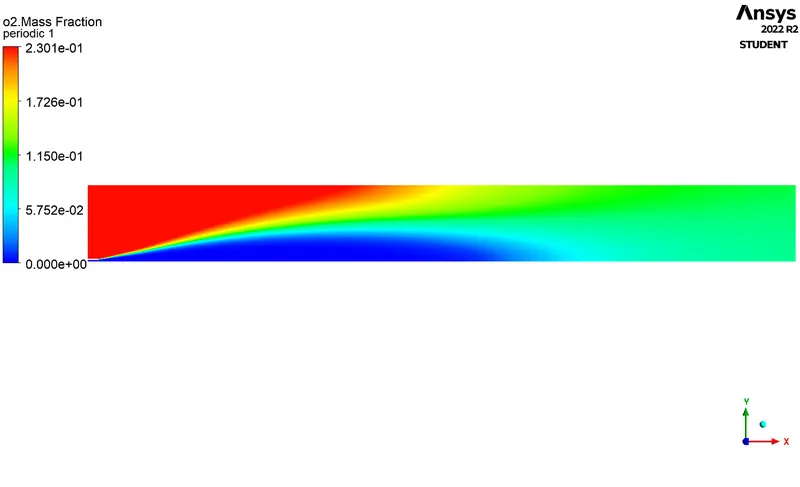
4) O2 Contour
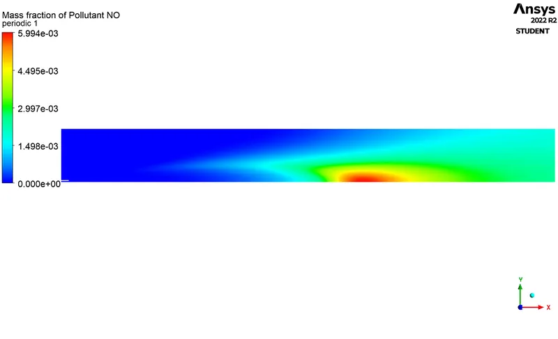
5) NOX Contour
6) Soot Contour
Case:4-
1) Residuals
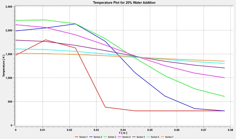
2) Temperature Distrbution Profile
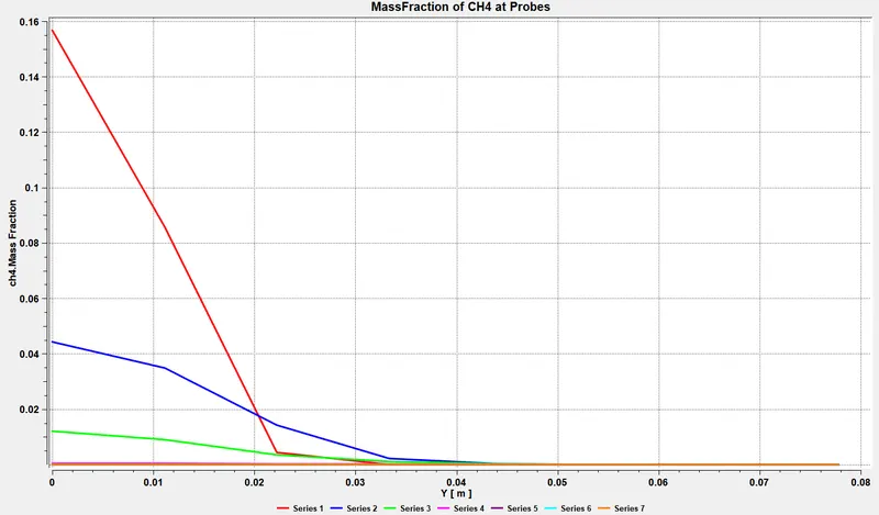
3) Mass Fraction of CH4
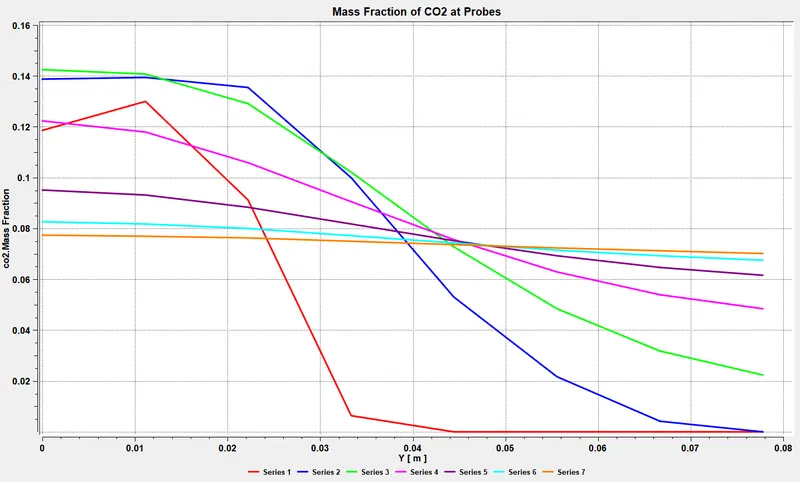
4) Mass Fraction of CO2
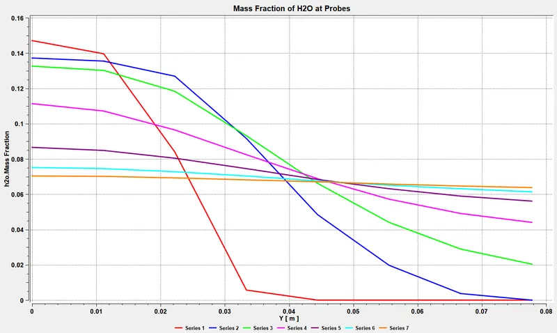
5) Mass Fraction of H20
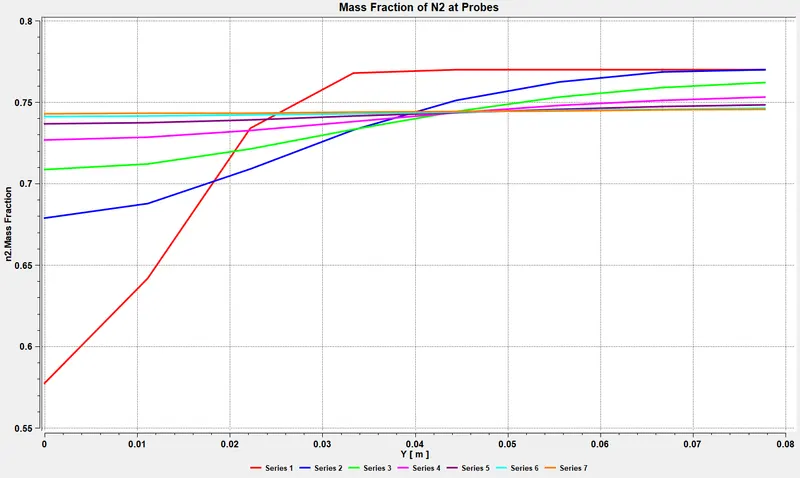
6) Mass Fraction of N2
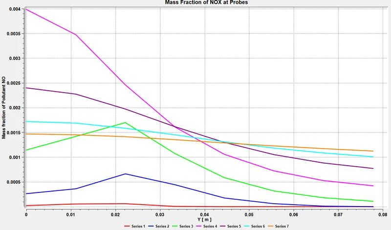
7) Mass Fraction of NOX
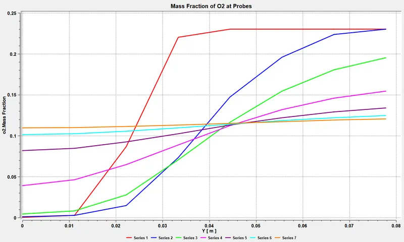
8) Mass Fraction of O2
9) Mass Fraction of Soot
Contours:
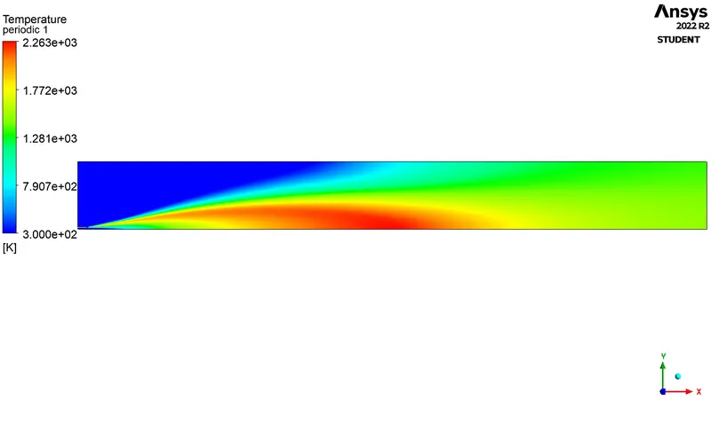
Temperature Contour
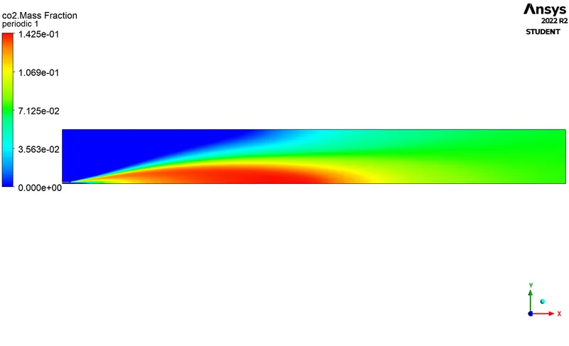
1) CO2 Contour
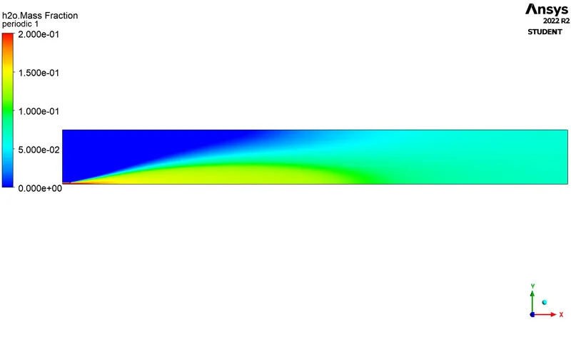
2) H2O Contour
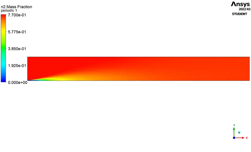
3) N2 Contour
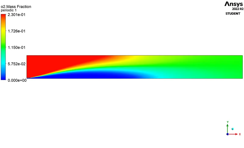
4) O2 Contour
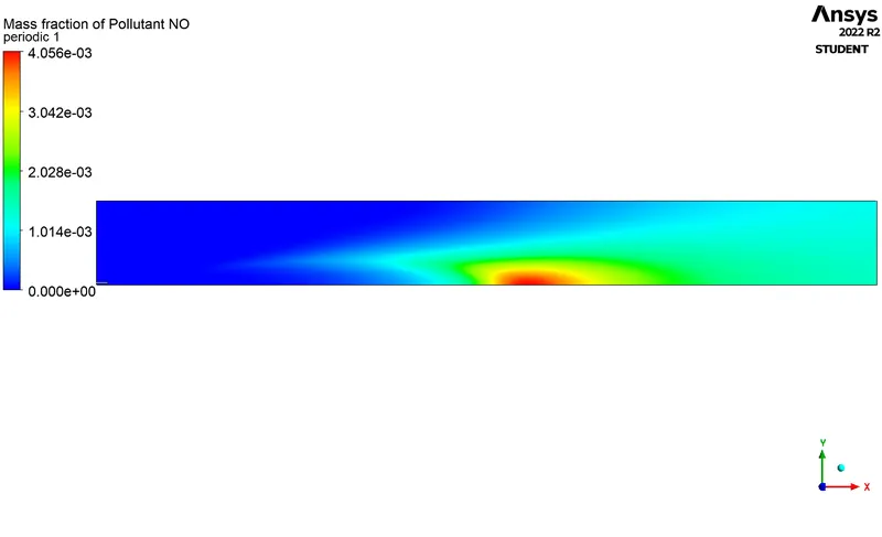
5) NOX Contour
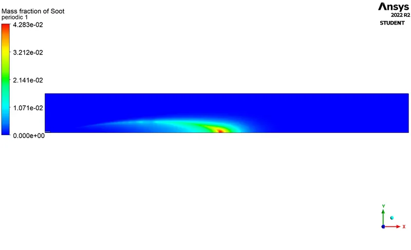
6) Soot Contour
Case:5 -
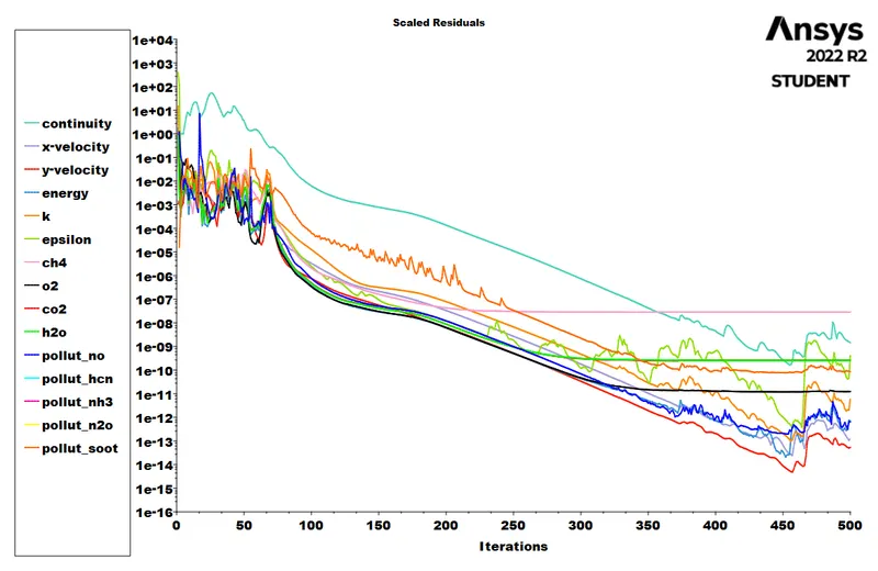
1) Residuals
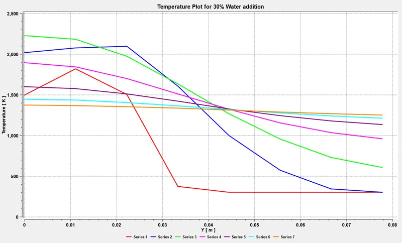
2) Temperature Distrbution Profile
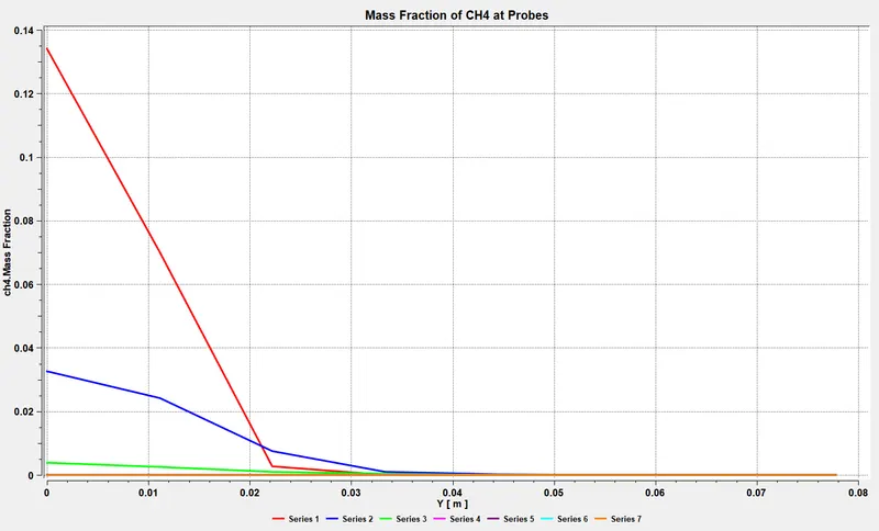
3) Mass Fraction of CH4
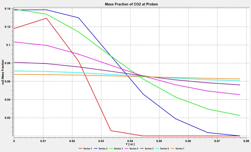
4) Mass Fraction of CO2
5) Mass Fraction of H20
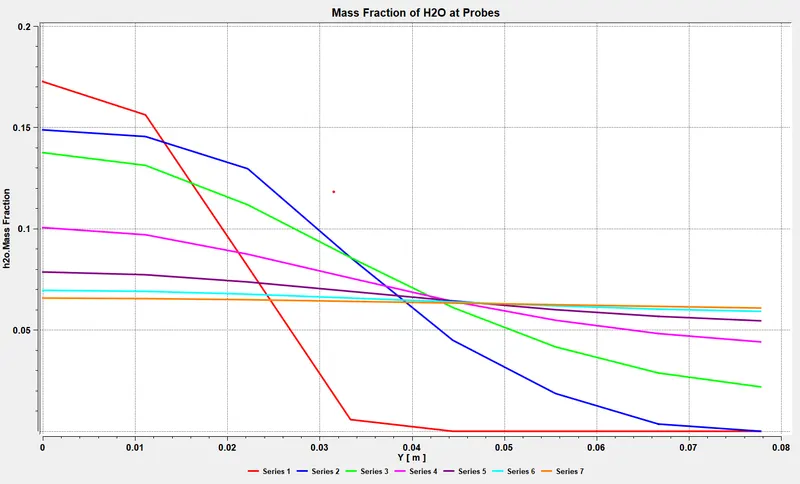
6) Mass Fraction of N2
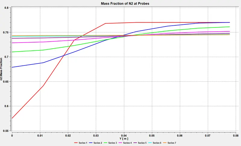
7) Mass Fraction of NOX
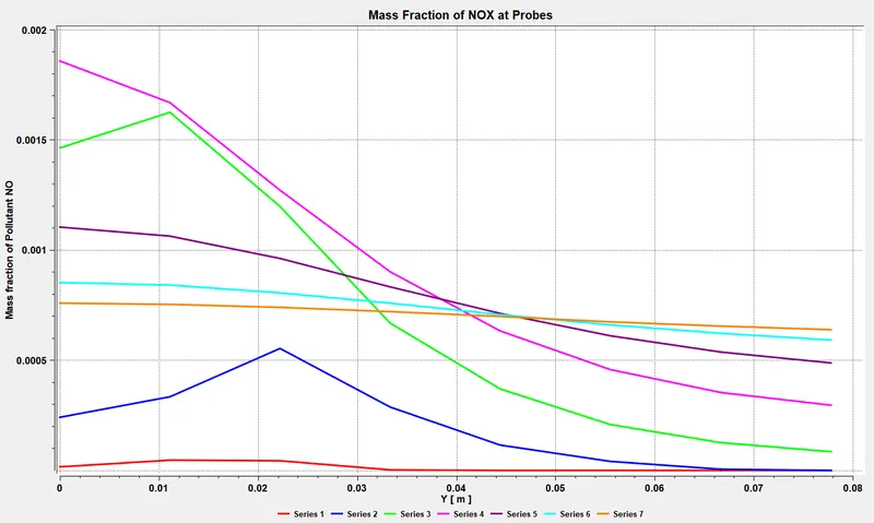
8) Mass Fraction of O2
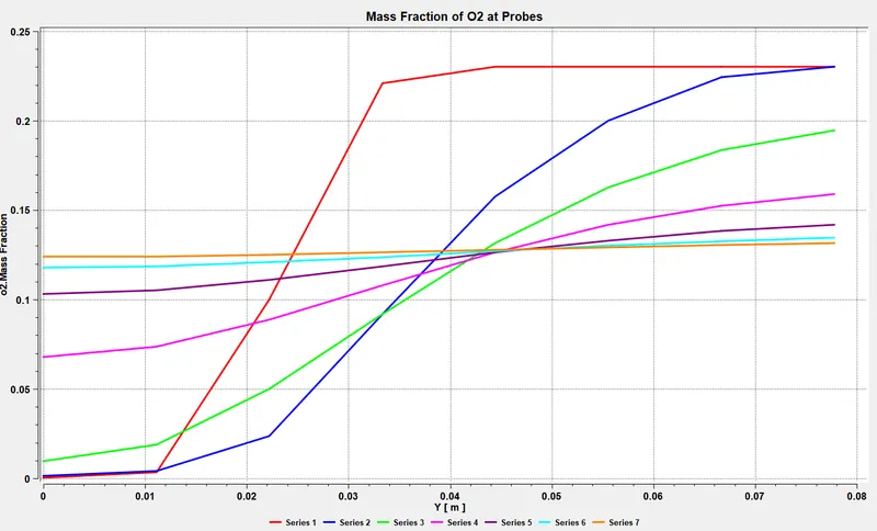
9) Mass Fraction of Soot
Contours:
Temperature Contour
1) CO2 Contour
2) H2O Contour
3) N2 Contour
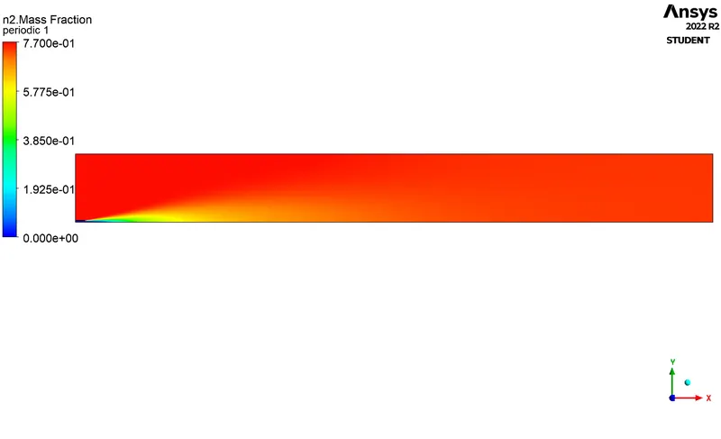
4) O2 Contour
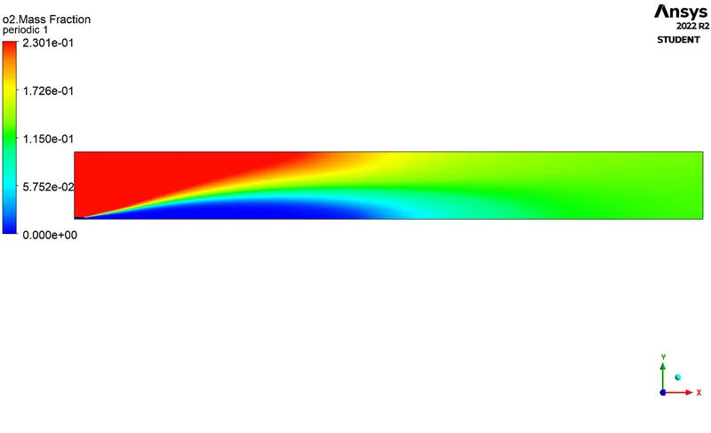
5) NOX Contour
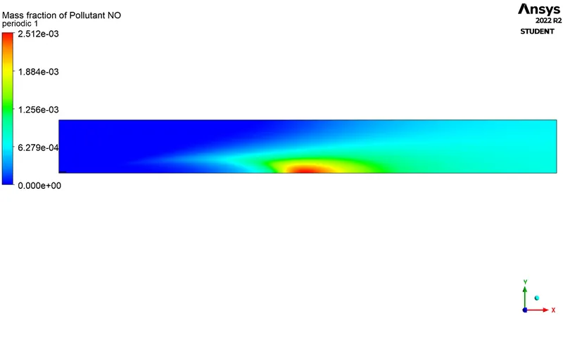
6) Soot Contour
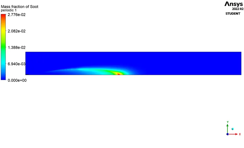
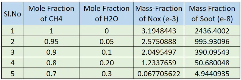
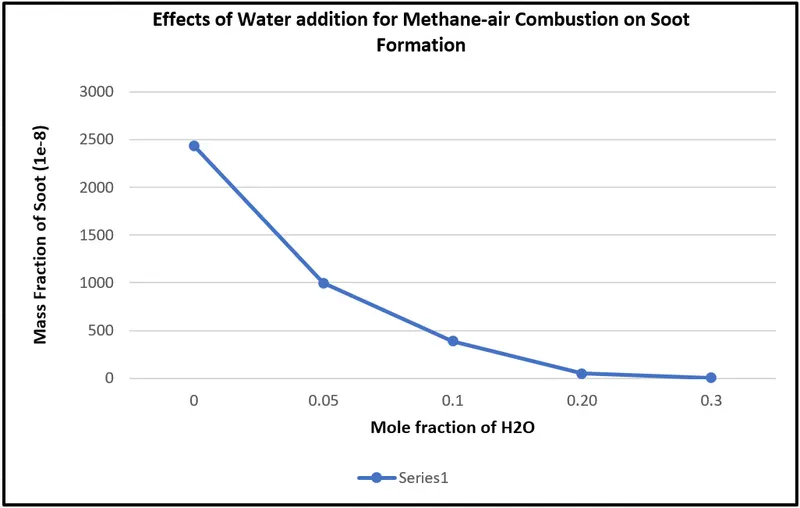
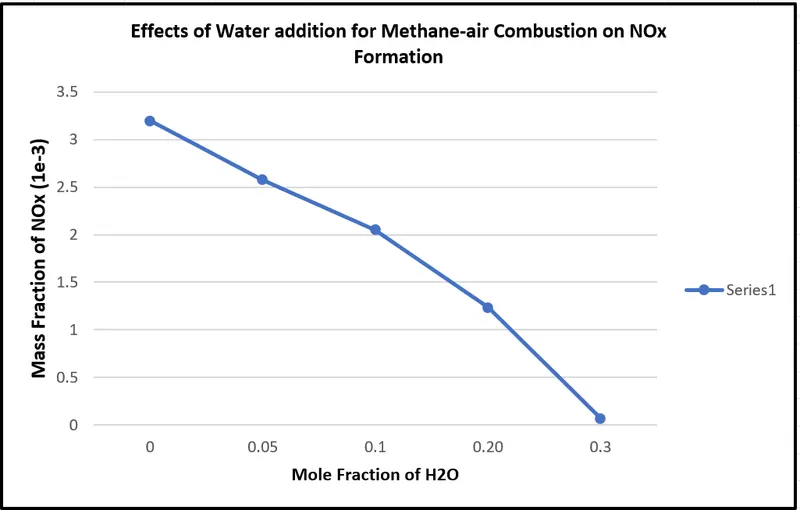
Effects of addition of H2O :
Conclusion:-
- Diluting fuel with H2O does indeed reduce the formation of harmful pollutants such as NOX and soot at the outlet.
- The rate of reduction in the concentration of soot is greater than that of NOX when diluting the fuel with water.
- Addition of water is also lead to decrease in temperature of combustor
- Fuel dilution by H2O is a great way to reduce emissions. However, a trade-off must be made between the performance required and the dilution amount.
- Since soot value decreases with dilution we can say there is less wastage of fuel, i.e. complete combustion occurs.
- Eddy - dissipation model(Turbulence Chemistry Interaction) helps us to model combustion via turbulence mixing without the presence of an ignition source.