Week 10 - Simulating Combustion of Natural Gas.
Aim:
Part 1:
To perform a combustion simulation on the combustor model and plot the variation of the mass fraction of the different species in the simulation.
Part 2:
Adding water content in the fuel and observe the effect of the results.
Introduction:
Combustion is a high-temperature exothermic redox chemical reaction between a fuel (the reductant) and an oxidant, usually atmospheric oxygen. When the fuel and air react, it releases heat and light energy. This Heat and light energy results in the flame. Once the reaction takes place between the fuel and oxygen it will produce flames, heat and unburnt gases.
Uncatalyzed combustion in the air requires relatively high temperatures. Complete combustion is stoichiometric concerning the fuel, where there is no remaining fuel, and ideally, no residual oxidant. Thermodynamically, the chemical equilibrium of combustion in air is overwhelmingly on the side of the products. However, complete combustion is almost impossible to achieve, since the chemical equilibrium is not necessarily reached, or may contain unburnt products such as carbon monoxide, hydrogen and even carbon (soot or ash). Thus, the produced smoke is usually toxic and contains unburned or partially oxidized products. Any combustion at high temperatures in atmospheric air, which is 78% nitrogen, will also create small amounts of several nitrogen oxides, commonly referred to as NOx, since the combustion of nitrogen is thermodynamically favoured at high, but not low temperatures. Since burning is rarely clean, fuel gas cleaning or catalytic converters may be required by law.
Possible types of combustion simulation in Ansys fluent:
Based on mixing:
- Non-Premixed Combustion (Direct or Late Injection)
- Premixed Combustion (Carburetor)
- Partially Premixed Combustion
Based on Phase:
- Fluid Phase (Volumetric reactions)
- Wall (Surface reactions)
- Particles (Surface reactions)
- Porous Regions (After-treatment System)
Based on mixing
Non-Premixed Combustion:
In non-premixed combustion, fuel and oxidizer enter the reaction zone in distinct streams. In this type of simulation, the mixing of fuel with air takes place at the combustion chamber. This model is used when fuel is directly injected at the time of combustion.
Non-Premixed Combustion simulation is suitable for diesel engine combustion.
Premixed Combustion:
In this type of simulation, the mixing of fuel with air takes place before the combustion chamber.
This type of simulation is suitable for petrol engine combustion where the air and fuel are mixed in the combustion chamber.
Partially Premixed Combustion:
In Partially Premixed Combustion simulation, the fuel and air are mixed partially before entering into the combustion chamber.
Partially Premixed Combustion (PPC) is a modern combustion process intended to be used in internal combustion engines of automobiles and other motorized vehicles in the future. Its high specific power, high fuel efficiency and low exhaust pollution have made it a promising technology. A PPC engine injects and premixes a charge during the compression stroke. Thus, the premixed charge is too lean to ignite during the compression stroke, the charge will ignite after the last fuel injection ends near TDC. The fuel efficiency and working principle of a PPC engine resemble those of a Diesel engine, but the PPC engine can be run with a variety of fuels. Also, the partially premixed charge burns clean.
Based on Phase
Fluid Phase:
The volumetric reaction takes place in the fluid region.
Wall:
Combustion takes place on a wall or surface. Example: Evaporation
Particle:
Combustion takes place on the surface of the particles. Example: Coal combustion.
Porous Regions:
Combustion takes place inside the pores(After the treatment system). These reactions take place above the high-pressure drop region.
Complete and Incomplete Combustion
Complete Combustion:
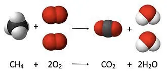
- In Complete combustion, oxygen reacts with a fuel to produce carbon dioxide and water.
- Because the air we breathe is only 21% oxygen, a large volume of air is required for complete combustion to take place.
- Combustion is an exothermic reaction that releases energy in the forms of heat and light.
- When a fuel undergoes complete combustion, it releases the maximum amount of energy from the fuel being reacted.
- Complete combustion is usually characterized by a blue flame.
Incomplete Combustion:
`4CH_4+5O_2->2CO+8H_2O+2C`
- Incomplete combustion is also a reaction between oxygen and fuel but the products are carbon monoxide, water and carbon.
- Incomplete combustion occurs when a combustion reaction occurs without a sufficient supply of oxygen.
- Incomplete combustion is often undesirable because it releases less energy than complete combustion and produces carbon monoxide which is a poisonous gas.
- Incomplete combustion can also produce pure carbon (soot) which is messy and can build up in equipment. (i.e.: chimneys)
- Incomplete combustion is characterized by an orange-coloured flame.
NOx
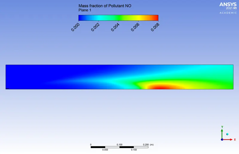
In atmospheric chemistry, NOx is a generic term for the nitrogen oxides that are most relevant for air pollution, namely nitric oxide (NO) and nitrogen dioxide (NO2). These gases contribute to the formation of smog and acid rain, as well as affecting tropospheric ozone.
NOx gases are usually produced from the reaction among nitrogen and oxygen during the combustion of fuels, such as hydrocarbons, in the air; especially at high temperatures, such as in car engines. In areas of high motor vehicle traffic, such as in large cities, the nitrogen oxides emitted can be a significant source of air pollution. NOx gases are also produced naturally by lightning.
In industrial boilers, NOx is primarily formed in two ways:
- thermal NOx
- fuel NOx
Thermal NOx is formed when nitrogen and oxygen in the combustion air combine with one another at high temperatures in a flame. Thermal NOx makes up the majority of NOx formed during the combustion of gases and light oils. The rate of NOx formation generally increases significantly above 2,800°F flame temperature.
Fuel NOx is formed by the reaction of nitrogen bound in the fuel with oxygen in the combustion air. It is rarely a problem with gaseous fuels. But in oils containing significant amounts of fuel-bound nitrogen, fuel NOx can account for up to 50% of the total NOx emissions.
A third and generally less important source of NOx formation is Prompt NOx which forms from the rapid reaction of atmospheric nitrogen with hydrocarbon radicals. Prompt NOx is generally minor compared to the overall quantity of NOx generated from combustion. However, as NOx emissions are reduced to extremely low limits, the contribution of this source becomes more important.
Soot
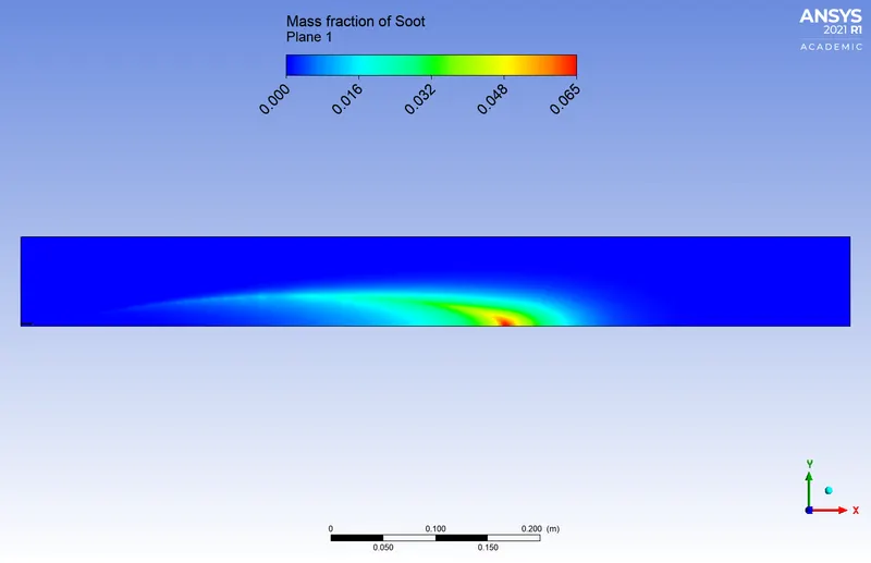
Soot, sometimes called lampblack or carbon black, is a fine black or brown powder that can be slightly sticky and is a product of incomplete combustion. A major component of soot is black carbon. Since soot is sticky, it tends to stick to exhaust pipes and chimneys where the combustion occurs. In pollution terms, soot is the common term for a type of particle pollution known as PM 2.5, which is particulate matter 2.5 micrometres in diameter or smaller. Soot is composed of a variety of chemicals and its exact composition depends strongly on what is being burned.
The formation of soot can be a problem. In places such as chimneys, the formation of soot can result in clogged chimneys that cannot draw out smoke as efficiently. This can lead to smokey fires or the inefficient use of fuel. If soot is allowed to build up in the chimney for too long, it can cause a fire. Additionally, soot is a pollutant and has a range of environmental and health effects.
A major component of soot is black carbon which absorbs lighter than any other form of particulate matter. Black carbon can absorb 1 million times more energy than the same mass of carbon dioxide. This absorption of energy and its interaction with clouds means that black carbon is a major concern for climate change. It is linked to higher temperatures and the melting of ice and snow, particularly in sensitive regions such as the Arctic and the Himalayas.
Soot forms as a result of incomplete combustion. To achieve incomplete combustion instead of complete combustion, the fuel must burn at a lower temperature with a slightly reduced supply of oxygen. When the fuel burns, it breaks into small particles that include soot, which settles out as a dark powdery deposit. The formation of soot is an issue as it is one of the byproducts of fossil fuel combustion - particularly from coal. It is emitted by a wide range of sources both industrial and residential and enters the air causing air pollution.
The incomplete combustion is necessary to produce soot results in the formation of dioxins and other toxic compounds. The small size of particulate matter allows it to easily enter the lungs and bloodstream. This can cause serious effects including heart attacks, bronchitis, aggravated asthma, strokes, and even premature death.
In this challenge, we are going to analyze the combustion inside the chamber along with the temperature and mass fraction of each component.
Steps in combustion simulation:
- Geometry
- Meshing
- Setup
- Solution
- Result
Geometry:
Importing the solid model:
The first step is importing the solid model of the combustion chamber.
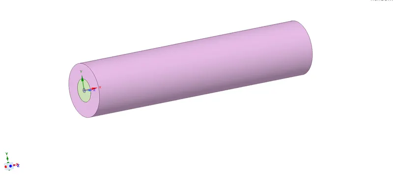
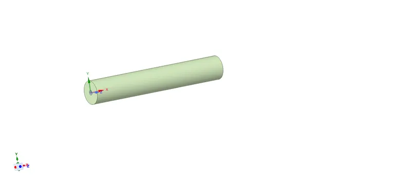
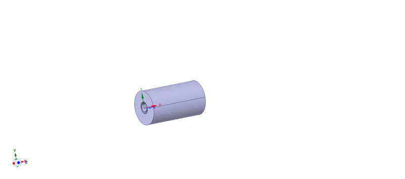
Component 2 Component 3
Creating the planes along the three-axis and splitting the body of the 3D model.
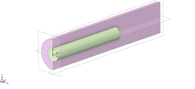
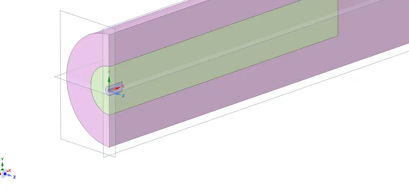
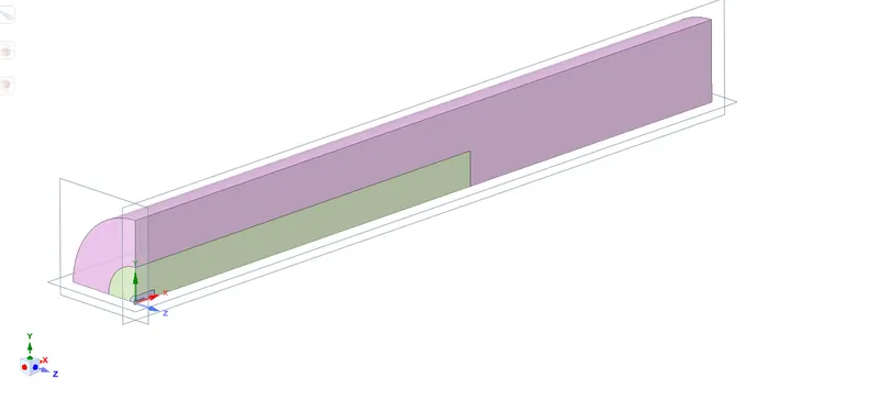
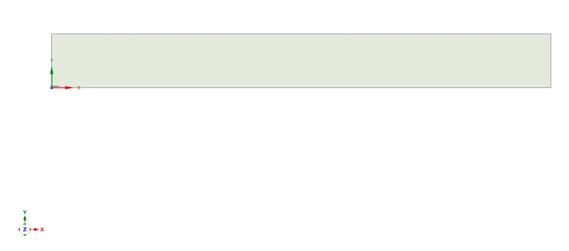
Extracting 2D model from the 3D geometry. Once the splitting is done, select the fluid surface and copy-paste it to the new geometry.
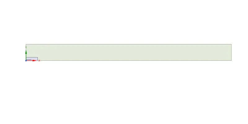
Combining the fuel and air inlet using the combine tool.
Mesh:
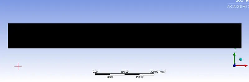
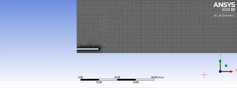
The 2D model is discretized into small elements of size 0.7mm.
The number of elements: 138486
The number of nodes:139794
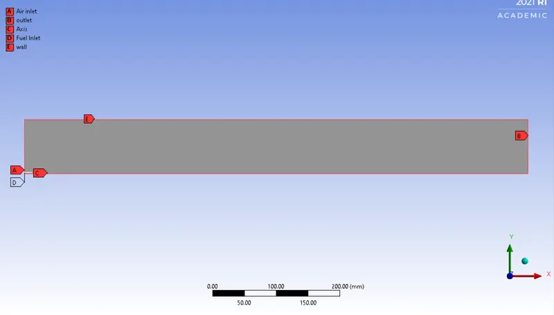
Named selection:
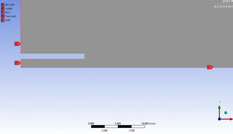
Mesh metric:
The mesh metric that identifies the elements according to their quality was employed and it can be seen that the elements of lowest quality are minimal, most of the elements have very high quality in the range of 0.9-1.

PART 1 Setup:
General:
Solver Type – Pressure based
Time – Steady
Axis symmetric
Model:
Energy is set on.
Viscous model – K-epsilon-Standard wall function
Species – methane-air
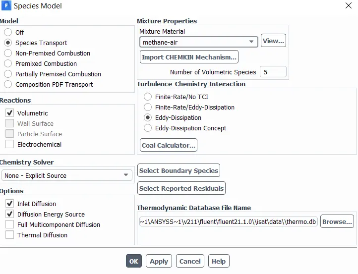
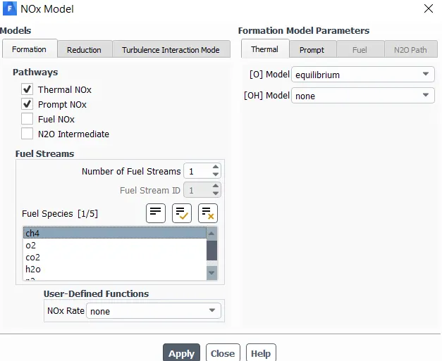
NOx setup image
Soot setup image
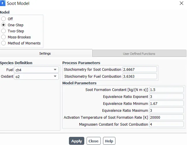
Material:
Air
Density: 998.2 Kg/m^3
Viscosity: 0.001003 Kg/m-s
Mixture –( methane, oxygen, carbon dioxide, water vapour, nitrogen)
Cell zones – surface- fluid
Boundary conditions:
Air Inlet- Velocity inlet = 0.5m/s
Fuel inlet – Velocity inlet = 80m/s
Outlet – Pressure outlet
Wall - wall
The reaction that's going to take place:
`CH_4+ a_rAir``-> Products`
`CH_4+a_r(O_2+3.76N_2)``->``aCO_2+bH_2O+cN_2`
Why 3.76?
It's because on a volume basis air consists of 21% `O_2`and 79% of `N_2`.
So,
`79/21=3.76`
`a_r` - Number of moles of `(O_2+3.76N_2)`
So, when we do balancing of this stoichiometric equation
- From carbon balancing, we find the value of a = 1
- From hydrogen balancing, we find the value of b = 2
4 = 2b
b = 2
- From oxygen balancing, we find the value of `a_r`=2
`2a_r=2a+b`
`a_r=a+b/2`
`a_r`=2
Fuel - 1 mole of `CH_4`
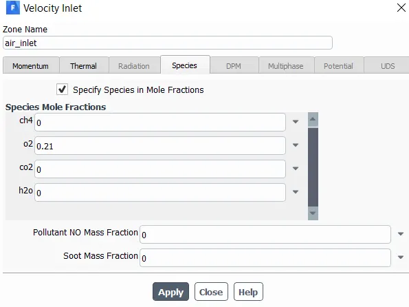
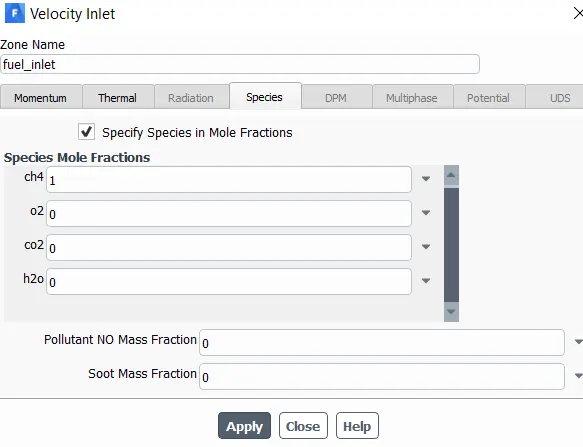
At fuel inlet, we will have only `CH_4`coming in, this means that the mole fraction or mass fraction is equal to 1. In other words, 100% of the incoming species through the fuel inlet is methane`.
Air - 2 moles of `O_2`+ 7.52 moles of `N_2`
mole fraction = Number of moles / Total number of moles
Mole fractions for `O_2`= `2/9.52=0.21`
Mole fractions for `N_2`= `7.52/9.52=0.79`
On a Mass fraction basis,
Mass fractions for `O_2`= 0.23
Mass fractions for `N_2`= 0.77
Report definition:
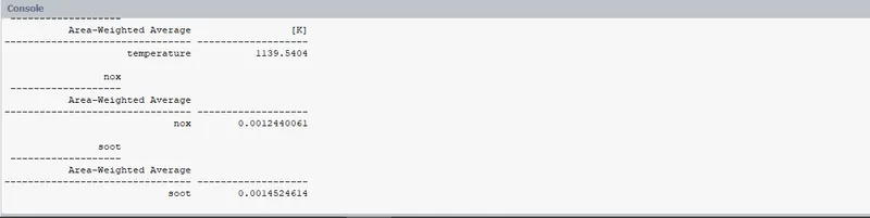
Area weighted Average of Temperature
Area weighted Average of Mass fraction of NOx
Area weighted Average of Mass fraction of Soot
Initialization: Hybrid initialization
Solution:
Residuals:
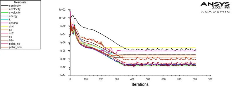
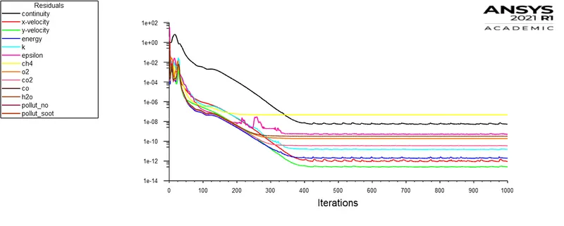
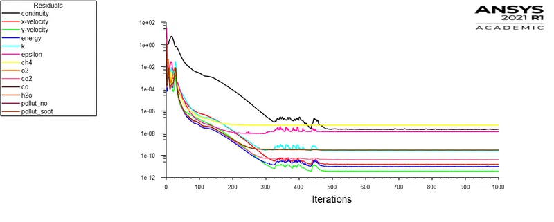
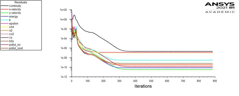
The calculation is set for 1000 iterations and it is converged at 450 iterations.
Report definition:
Results:
Contours:
Mass fraction of NOx
Mass fraction of Soot
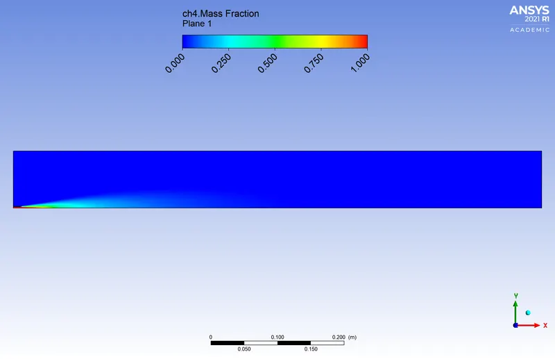
Mass fraction of CH4
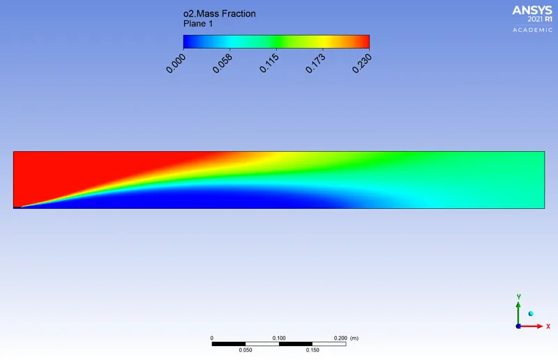
Mass fraction of O2
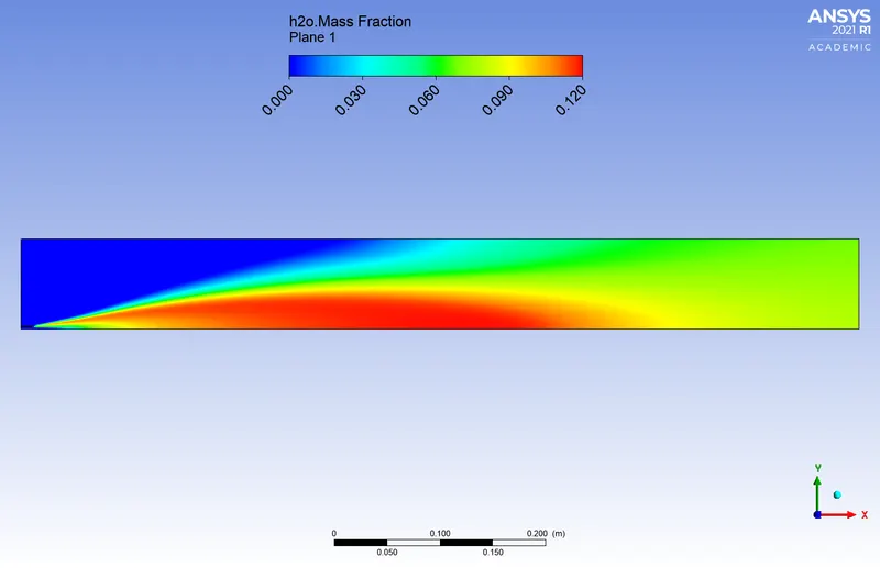
Mass fraction of H2O
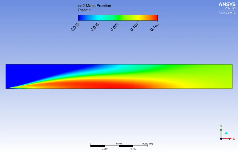
Mass fraction of CO2
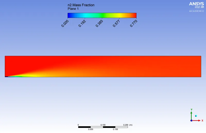
Mass fraction of N2
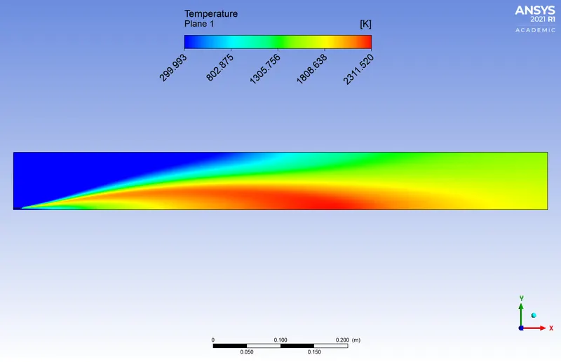
Temperature
Lines:
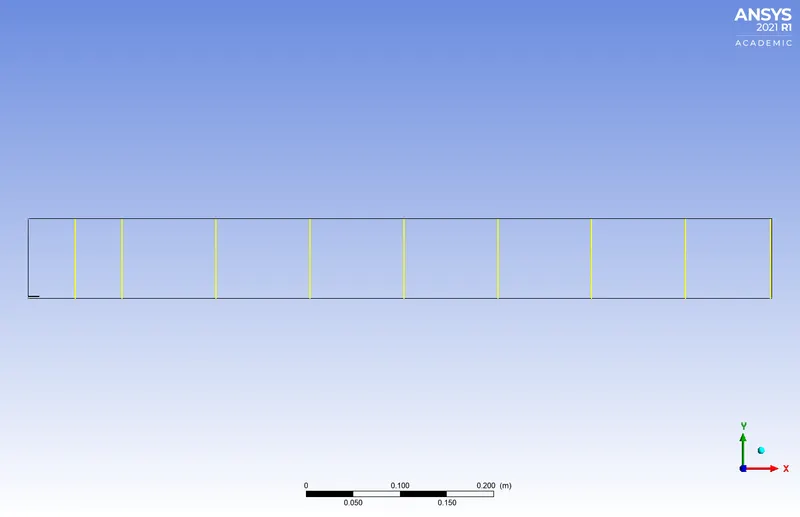
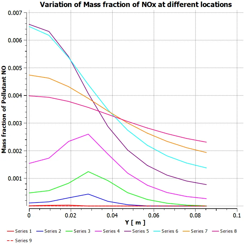
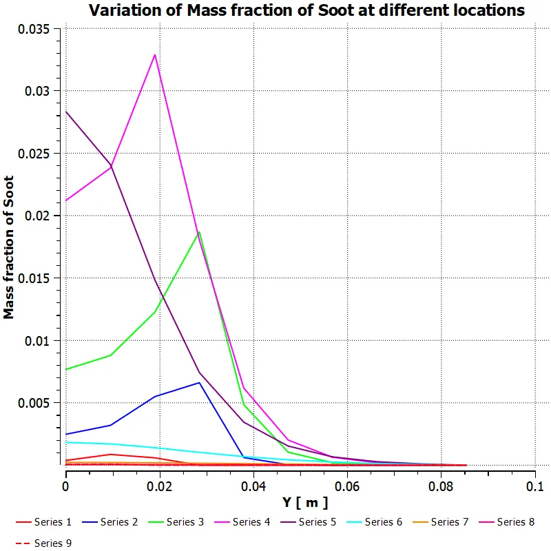
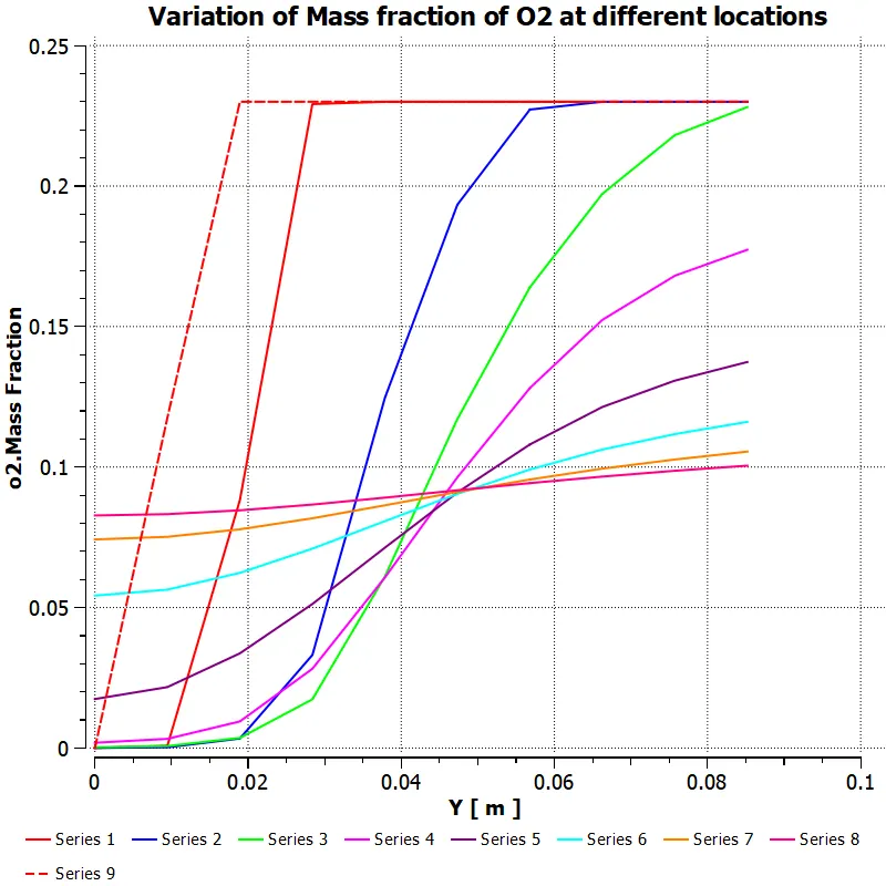
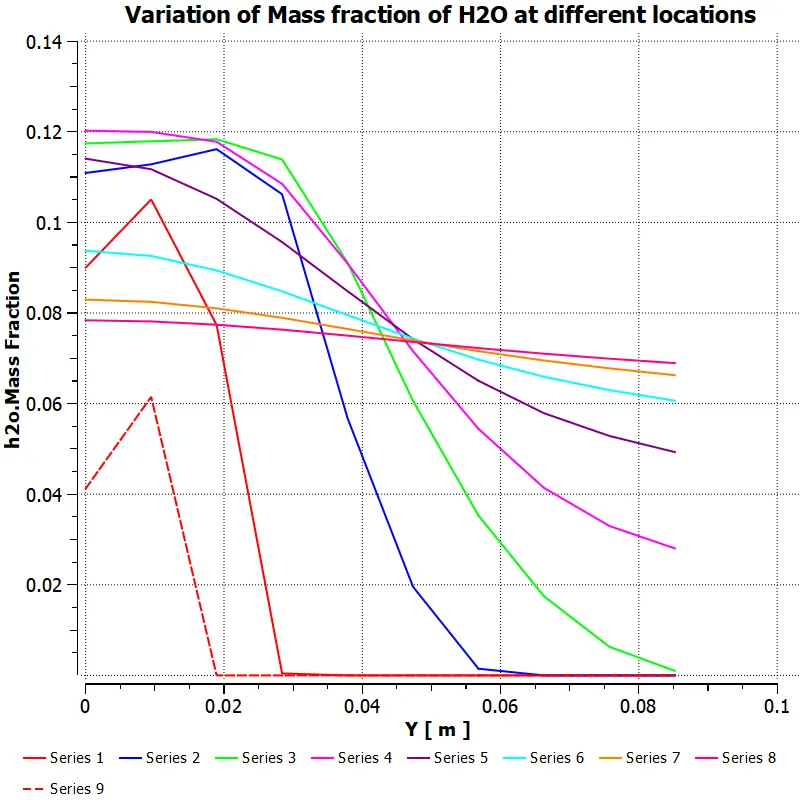
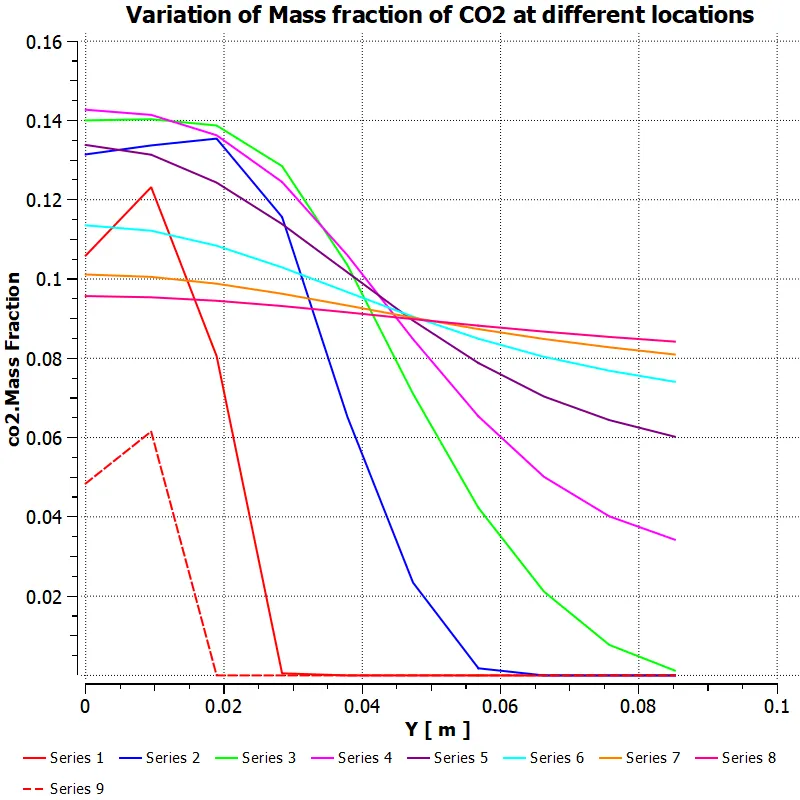
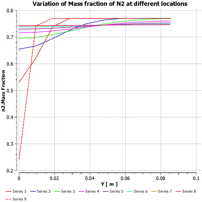
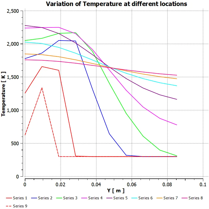
Series 1 : X = 0.1m
Series 2 : X = 0.2m
Series 3 : X = 0.3m
Series 4 : X = 0.4m
Series 5 : X = 0.5m
Series 6 : X = 0.6m
Series 7 : X = 0.7m
Series 8 : X = 0.79m
Series 9 : X = 0.05m
Charts:
Mass fraction of NOx
Mass fraction of Soot
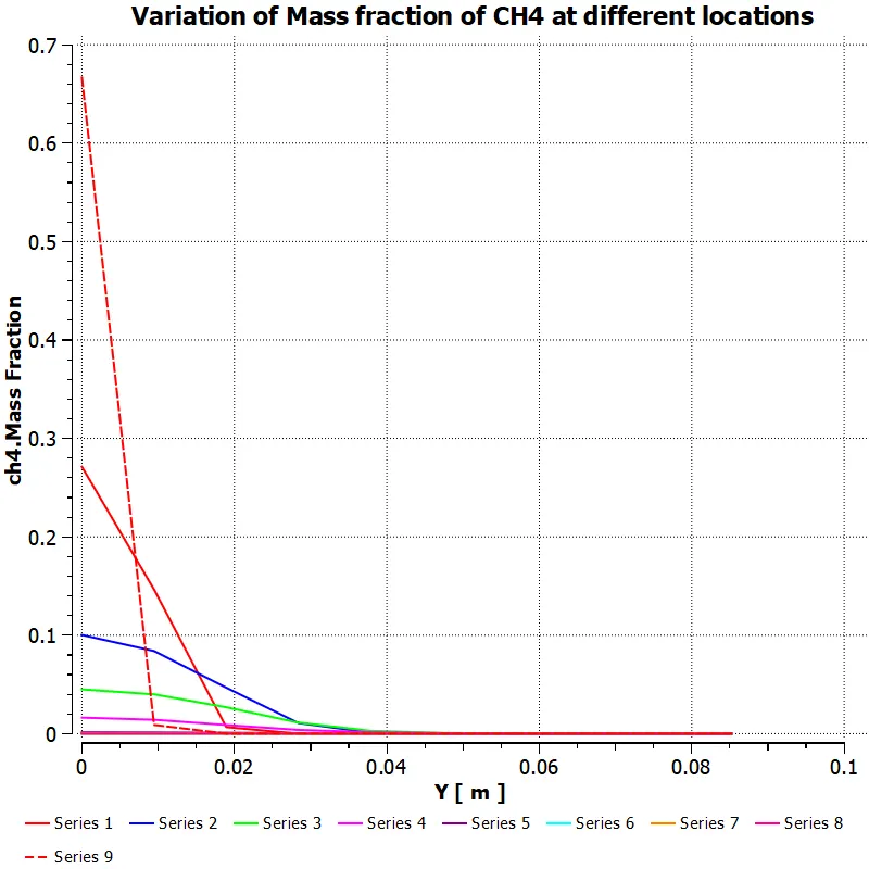
Mass fraction of CH4
Mass fraction of O2
Mass fraction of H2O
Mass fraction of CO2
Mass fraction of N2
Temperature
O2 chart:
For series 1 (x=0.1) and series 9 (x=0.05), Near the inlets, the mass fraction of O2 varies from 0 to 0.23 along the Y direction. At X= 0.3(series 3), mass fraction starts decreasing. This means that the burning of O2 molecules happens at this position.
For CH4, the fuel inlet is from the origin. Mass fraction of CH4 decreases from 1 to 0 along the Y direction. Far from inlets, the mass fraction of CH4 further reduces and becomes almost zero as we move in the Y direction, Here CH4 is not burnt completely.
PART 2 Setup:
General:
Solver Type – Pressure based
Time – Steady
Axis symmetric
Model:
Energy is set on.
Viscous model – K-epsilon-Standard wall function
Species – methane-air 2 step
NOx setup image
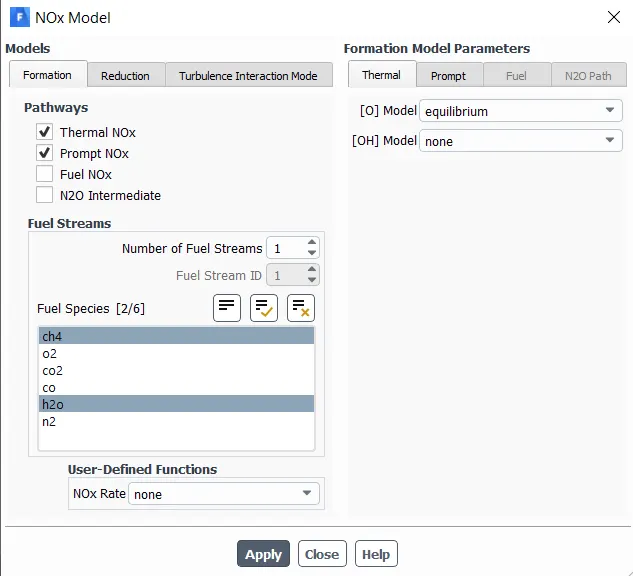
Soot setup will remain the same as part 1.
Material:
Air
Density: 998.2 Kg/m^3
Viscosity: 0.001003 Kg/m-s
Mixture –( methane, oxygen, carbon dioxide, carbon monoxide, water vapour, nitrogen)
Cell zones – surface- fluid
Boundary conditions:
Air Inlet- Velocity inlet = 0.5m/s
Fuel inlet – Velocity inlet = 80m/s
Similarly for adding 5% 10% 15% 20 % 25% 30% by mole of water content in the fuel, the boundary condition setup for fuel inlet will change as
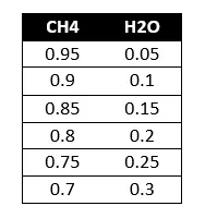
Outlet – Pressure outlet
Wall - wall
Report definition:
Area weighted Average of Temperature
Area weighted Average of Mass fraction of NOx
Area weighted Average of Mass fraction of Soot
Initialization: Hybrid initialization
Solution:
Residuals:
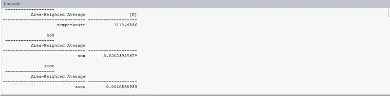
5% of the water in fuel content by mole
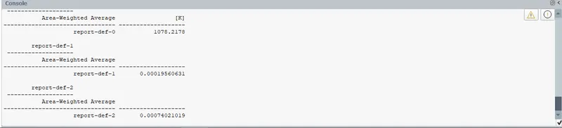
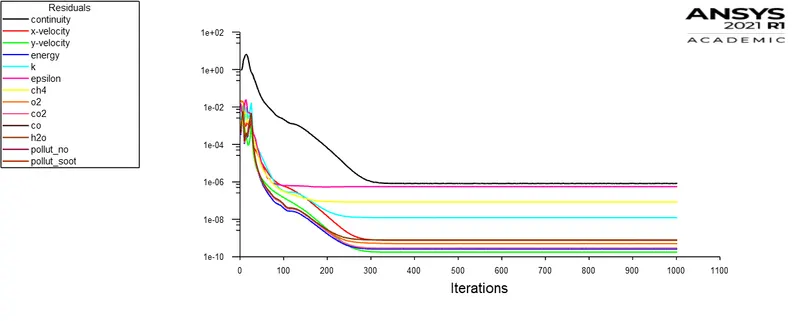
10% of the water in fuel content by mole
15% of the water in fuel content by mole
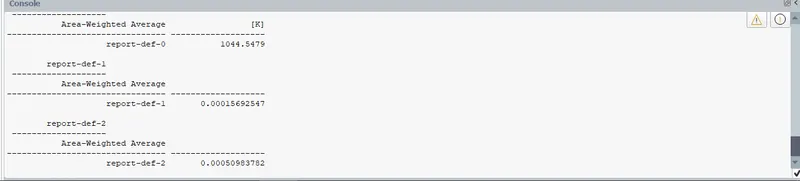
20% of the water in fuel content by mole
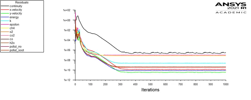
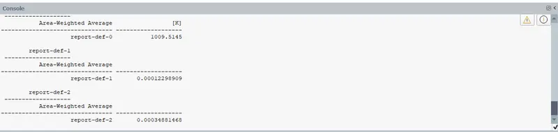
25% of the water in fuel content by mole
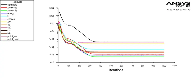
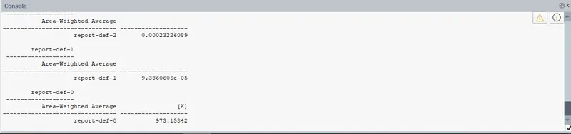
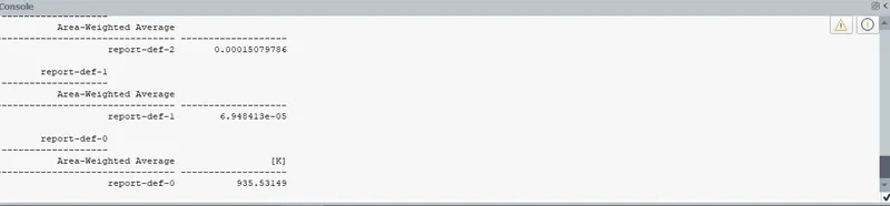
30% of the water in fuel content by mole
Results:
Contours:
Mass fraction of NOx
5% of the water in fuel content by mole
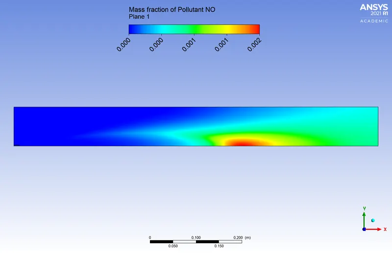
10% of the water in fuel content by mole
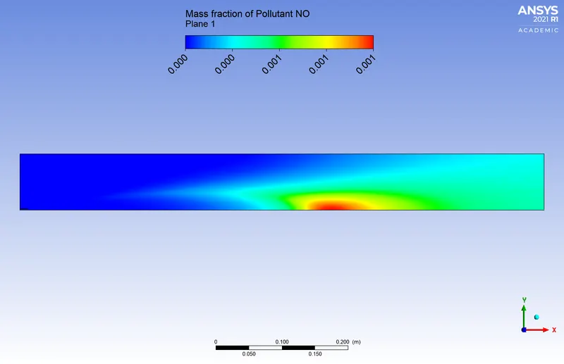
15% of the water in fuel content by mole
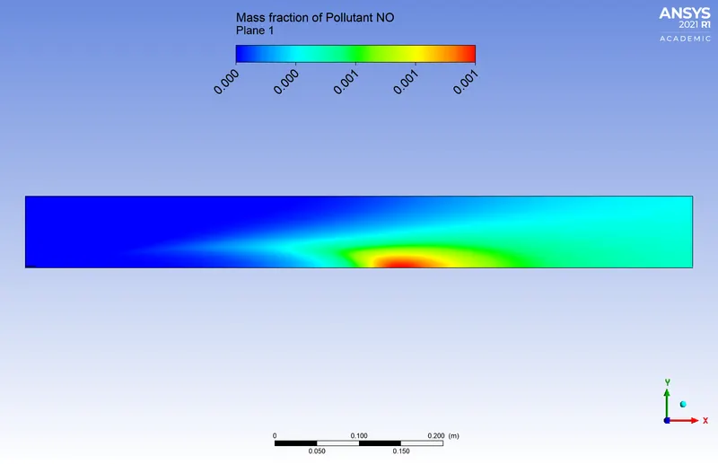
20% of the water in fuel content by mole
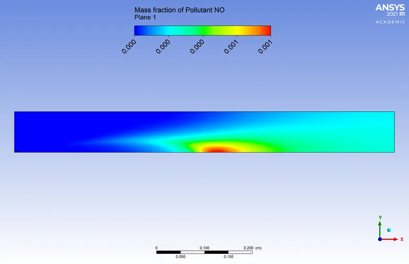
25% of the water in fuel content by mole
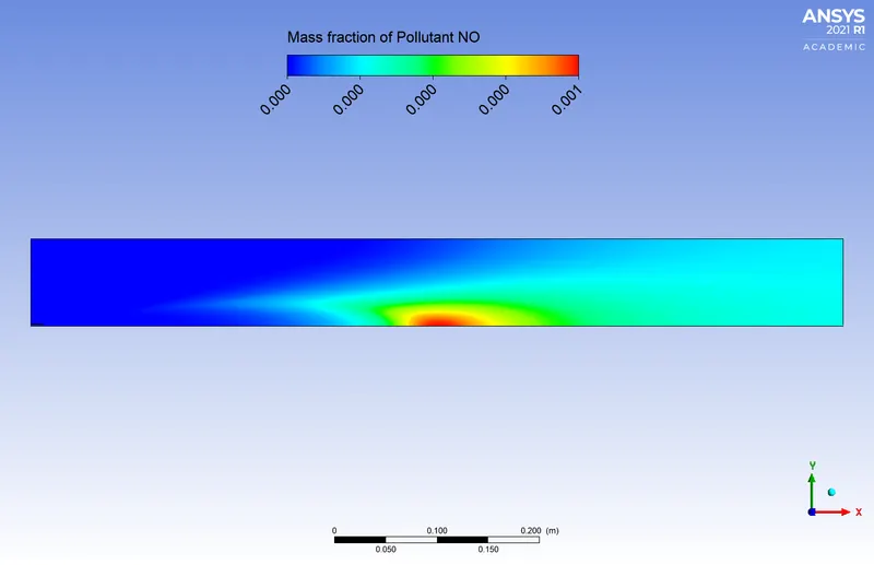
30% of the water in fuel content by mole
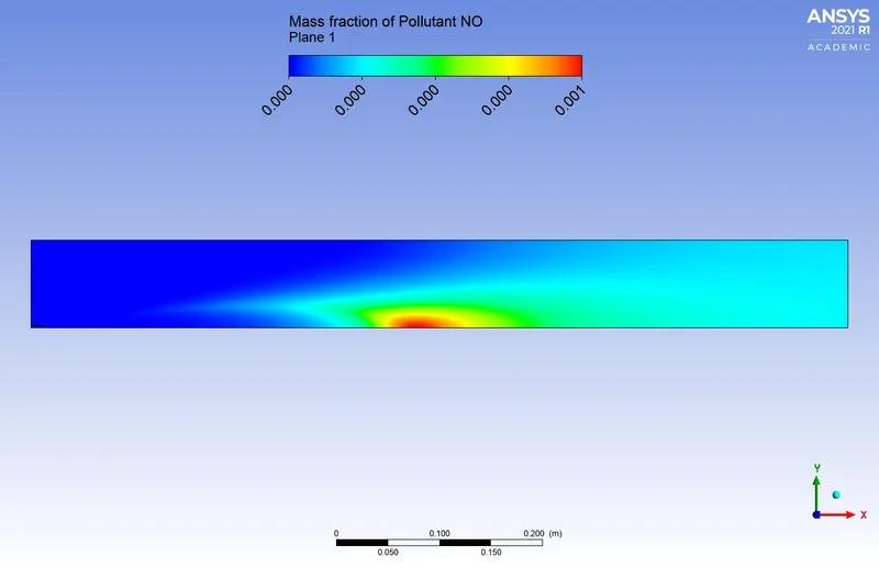
Mass fraction of Soot
5% of the water in fuel content by mole
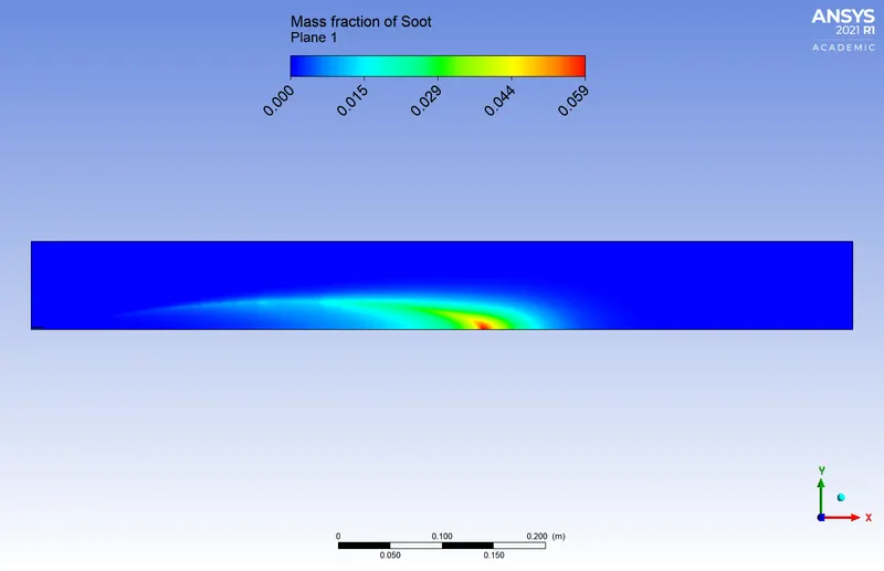
10% of the water in fuel content by mole
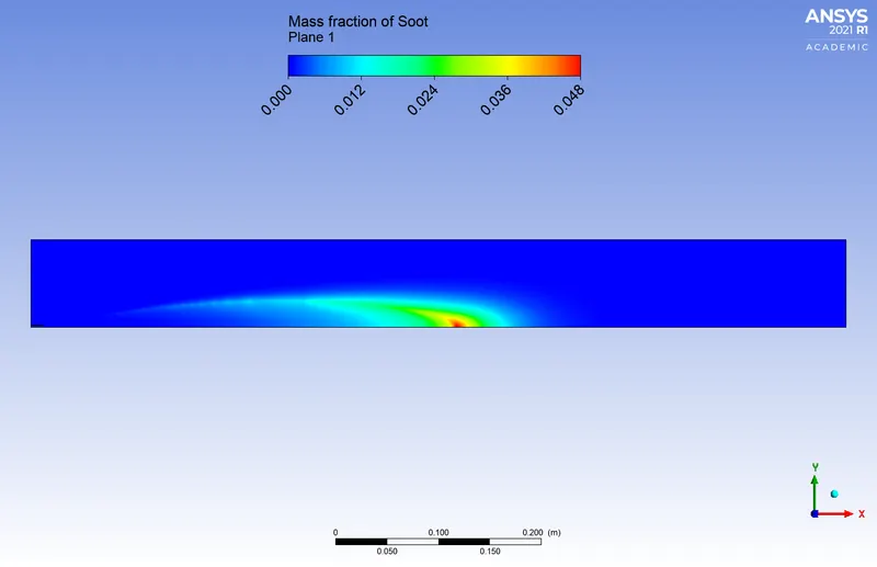
15% of the water in fuel content by mole
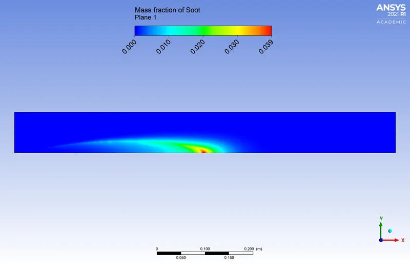
20% of the water in fuel content by mole
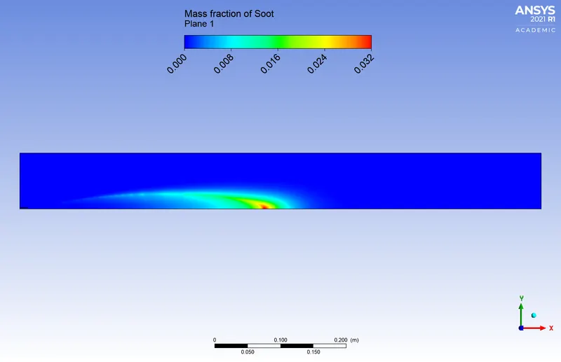
25% of the water in fuel content by mole
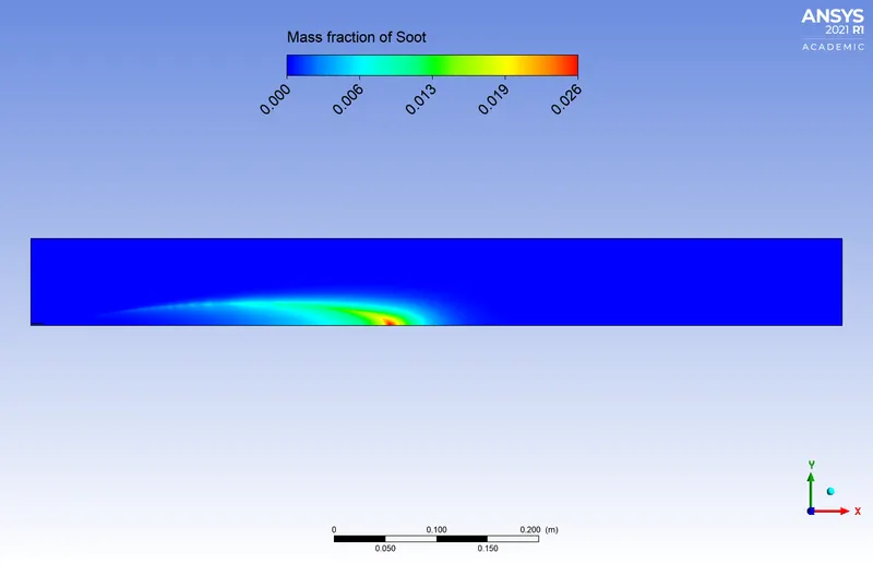
30% of the water in fuel content by mole
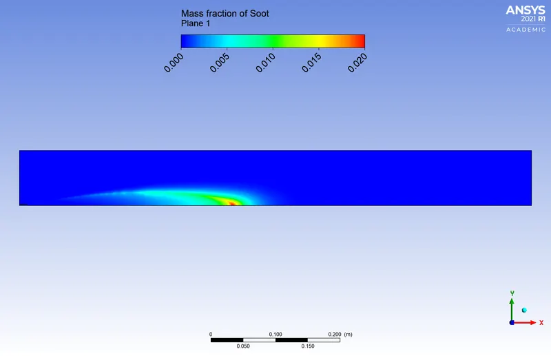
Mass fraction of H2O
5% of the water in fuel content by mole
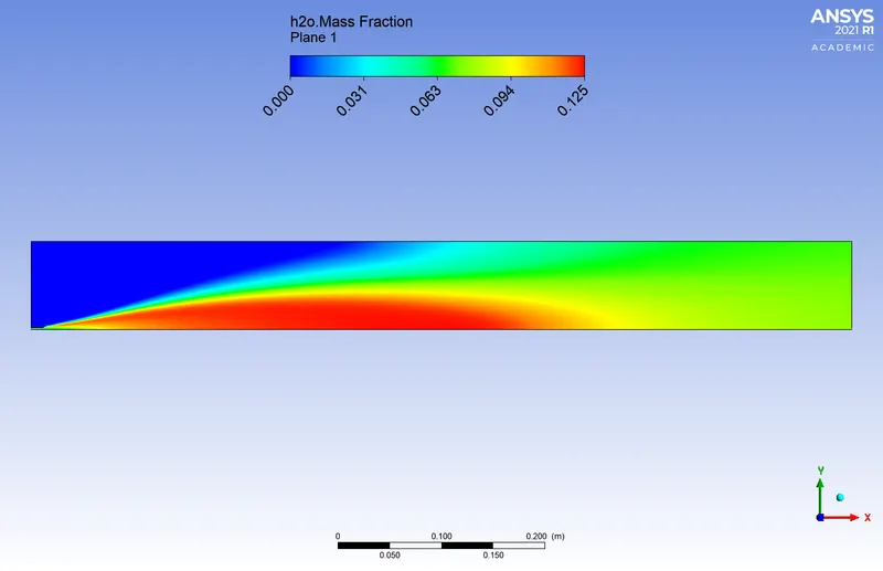
10% of the water in fuel content by mole
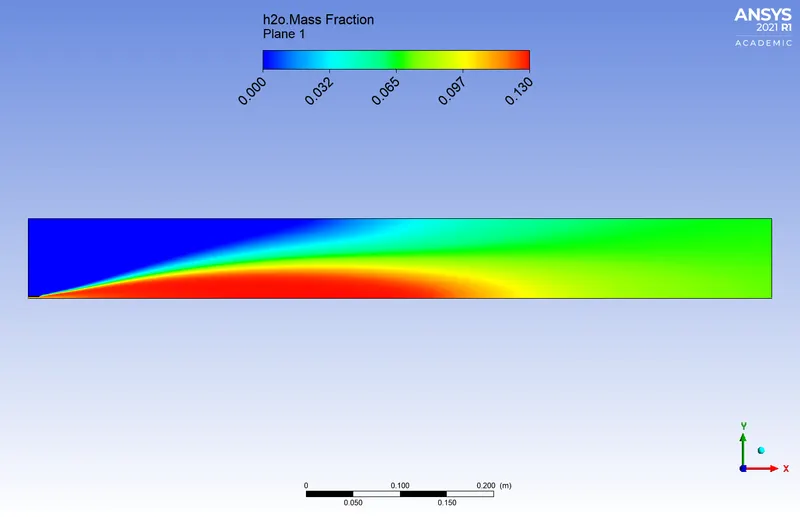
15% of the water in fuel content by mole
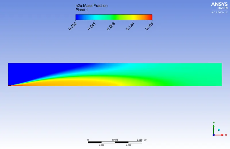
20% of the water in fuel content by mole
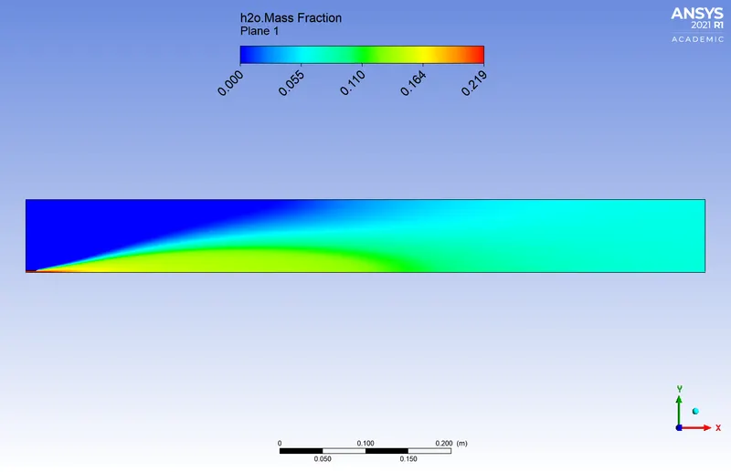
25% of the water in fuel content by mole
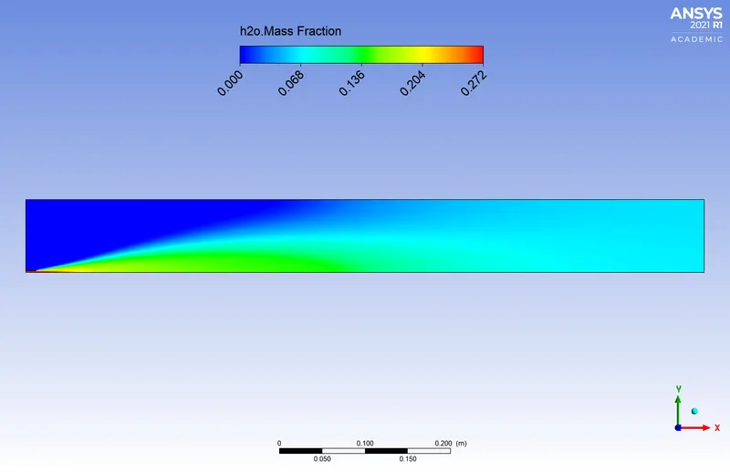
30% of the water in fuel content by mole
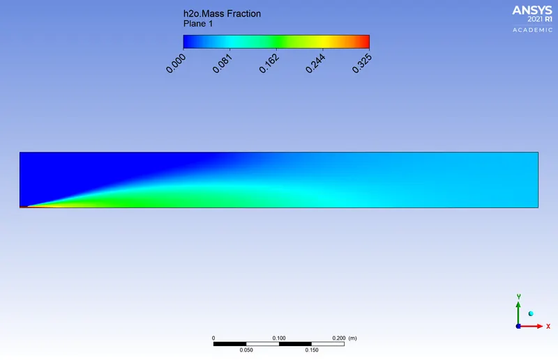
Temperature
5% of the water in fuel content by mole
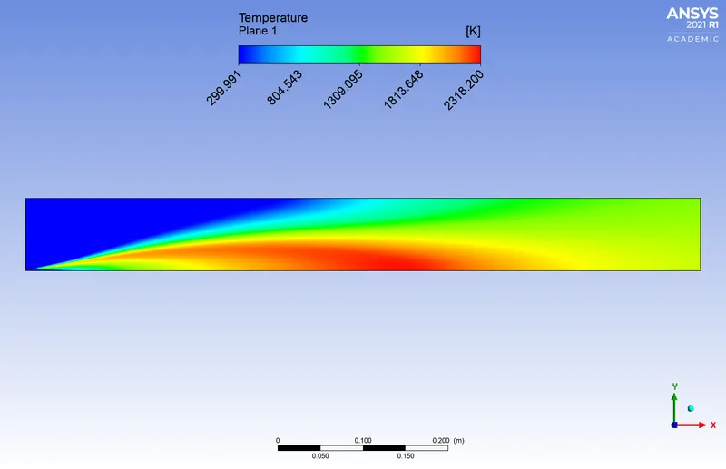
10% of the water in fuel content by mole
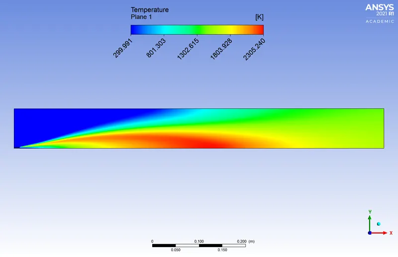
15% of the water in fuel content by mole
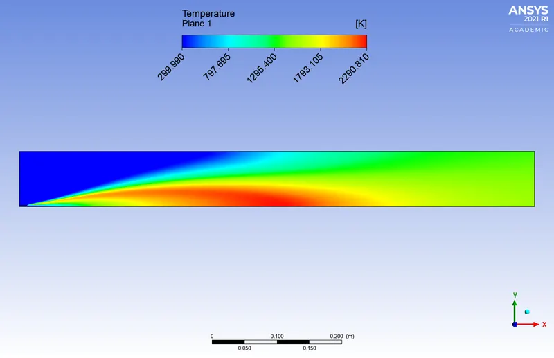
20% of the water in fuel content by mole
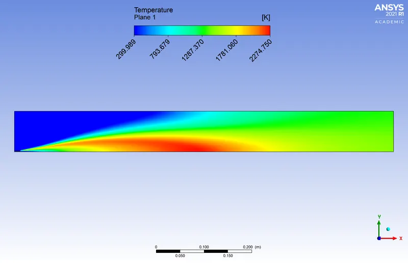
25% of the water in fuel content by mole
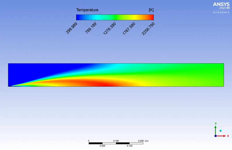
30% of the water in fuel content by mole
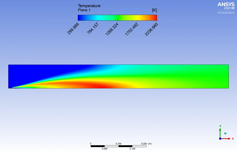
Charts:
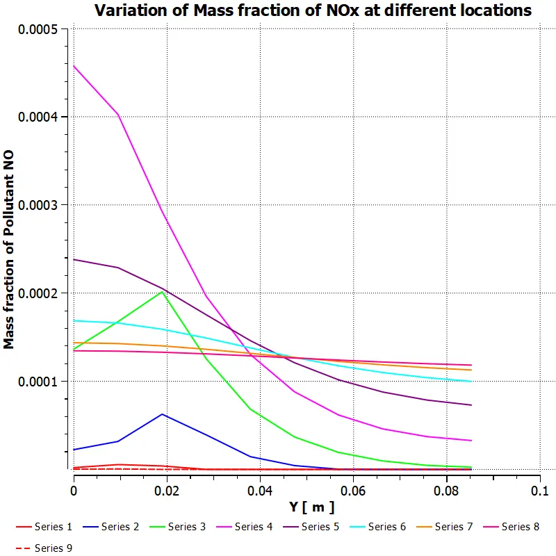
Mass fraction of NOx
5% of the water in fuel content by mole
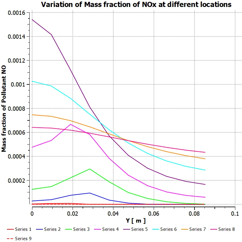
10% of the water in fuel content by mole
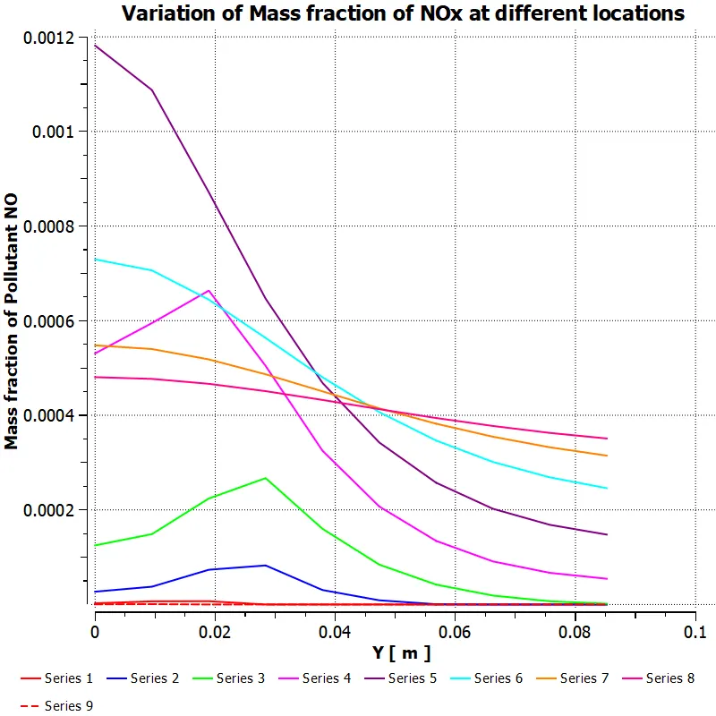
15% of the water in fuel content by mole
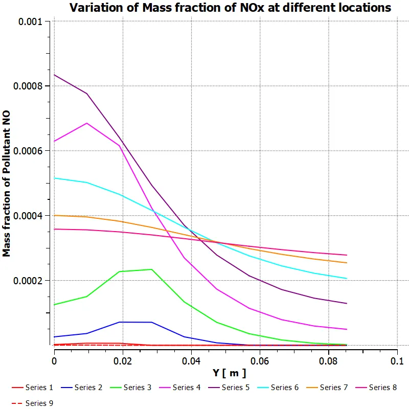
20% of the water in fuel content by mole
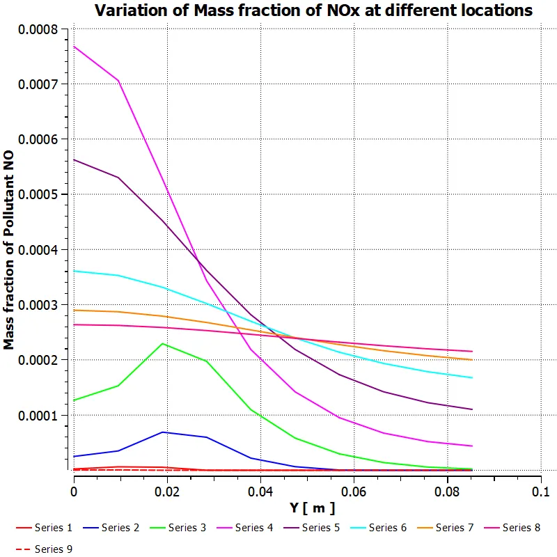
25% of the water in fuel content by mole
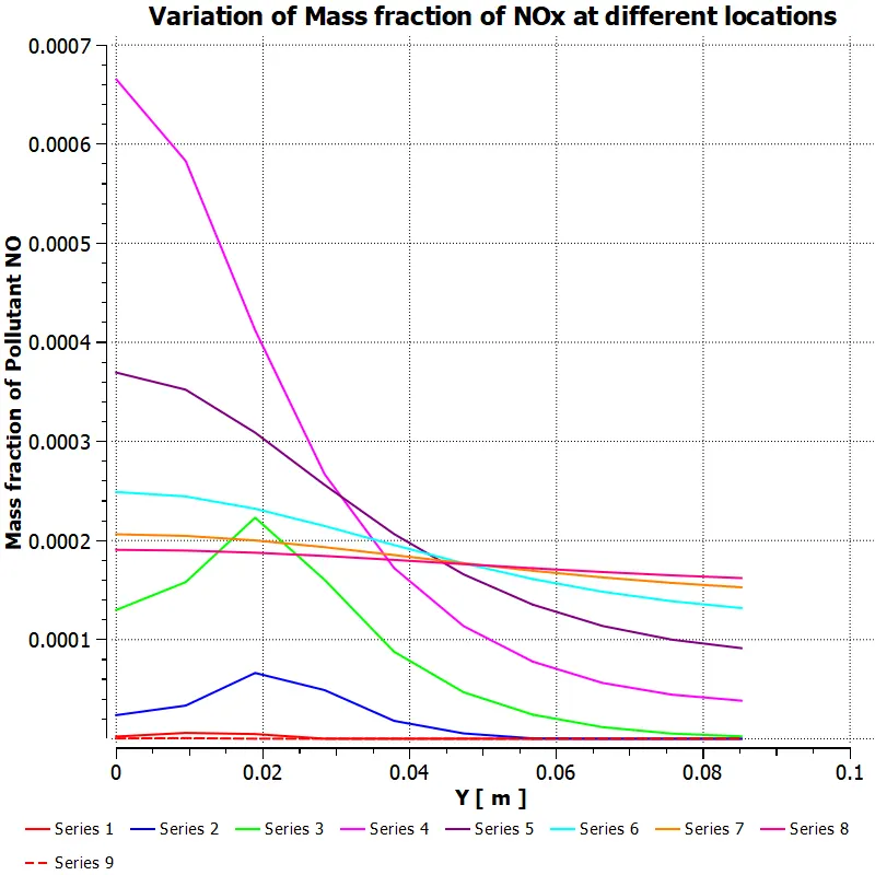
30% of the water in fuel content by mole
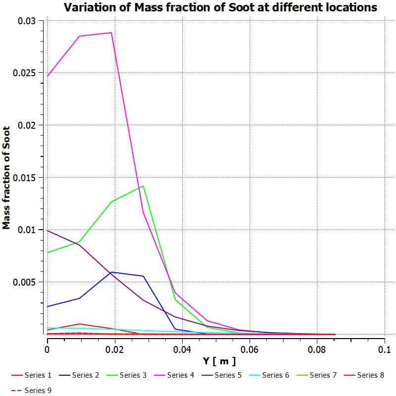
Mass fraction of Soot
5% of the water in fuel content by mole
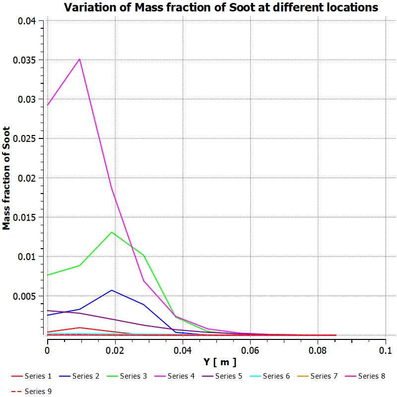
10% of the water in fuel content by mole
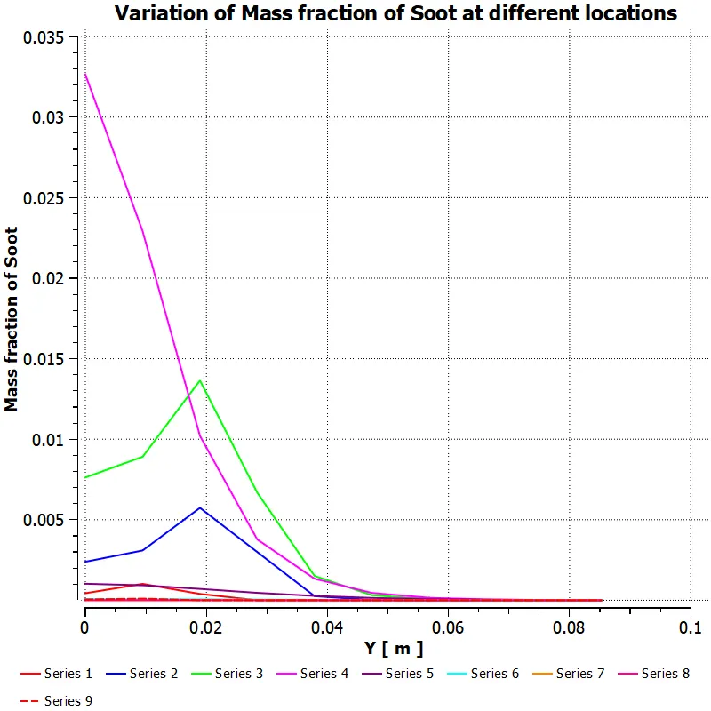
15% of the water in fuel content by mole
20% of the water in fuel content by mole
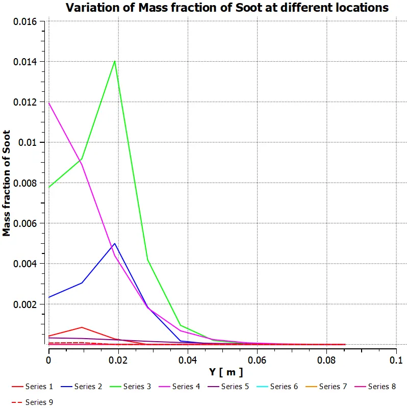
25% of the water in fuel content by mole
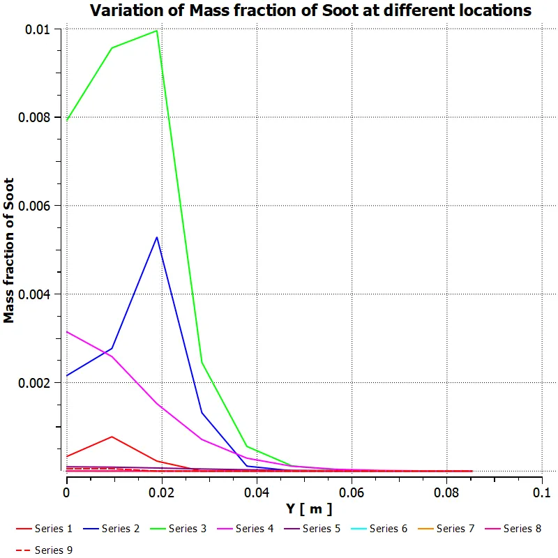
30% of the water in fuel content by mole
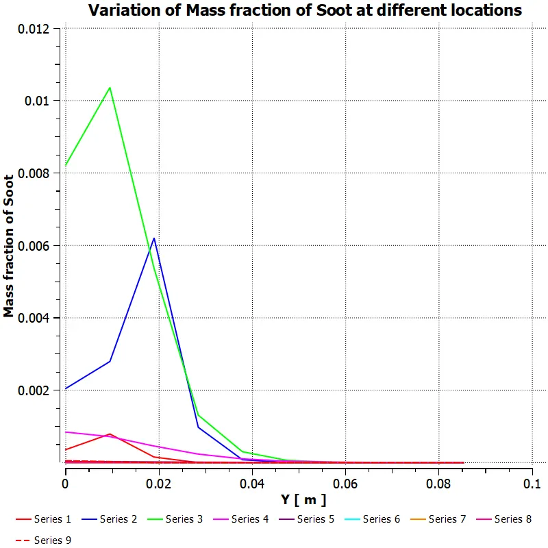
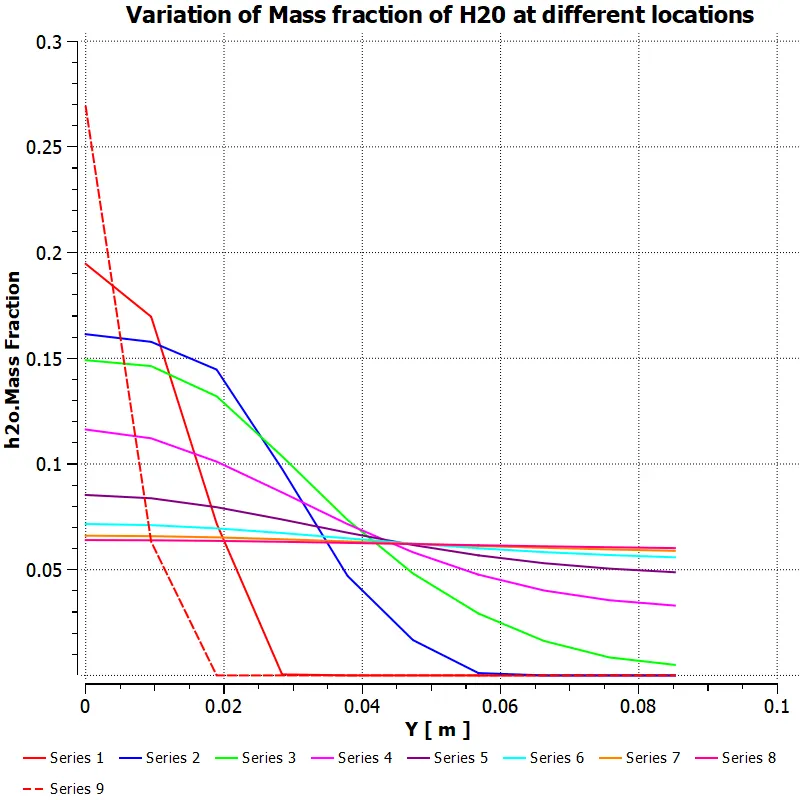
Mass fraction of H2O
5% of the water in fuel content by mole
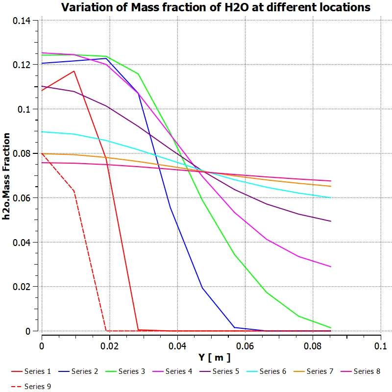
10% of the water in fuel content by mole
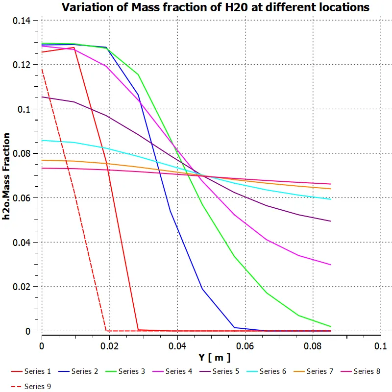
15% of the water in fuel content by mole
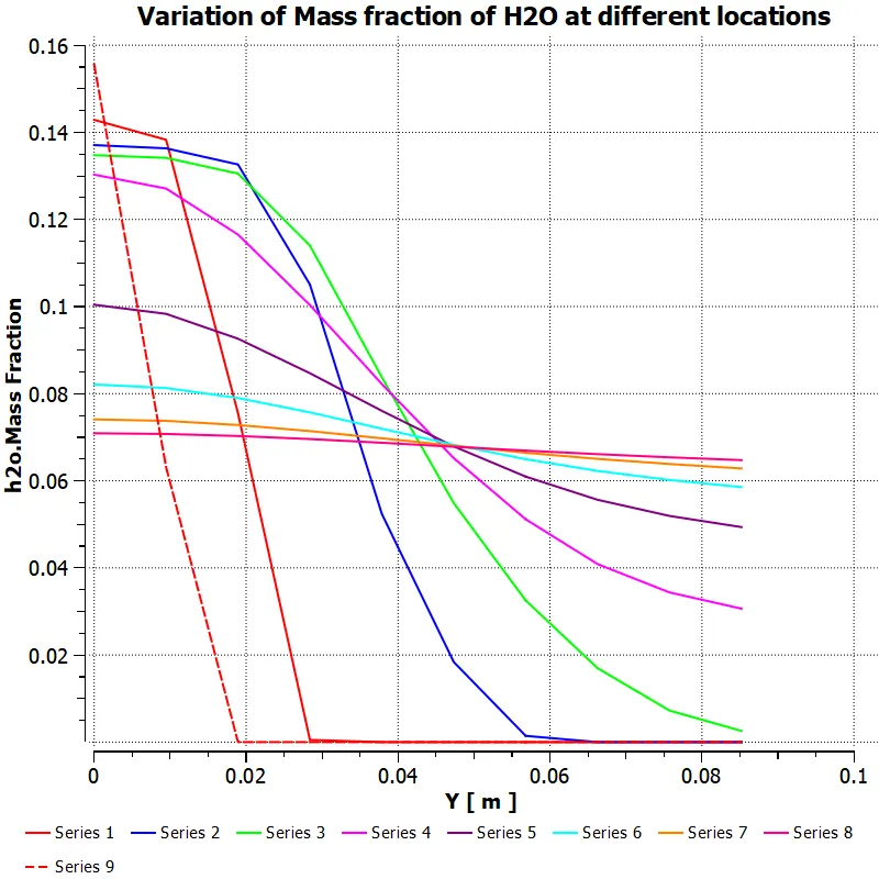
20% of the water in fuel content by mole
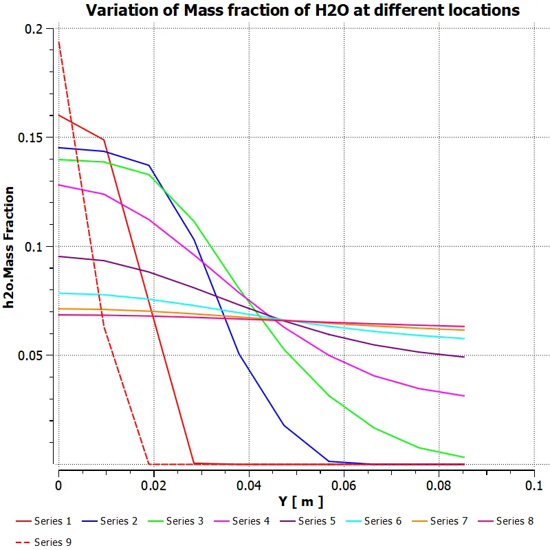
25% of the water in fuel content by mole
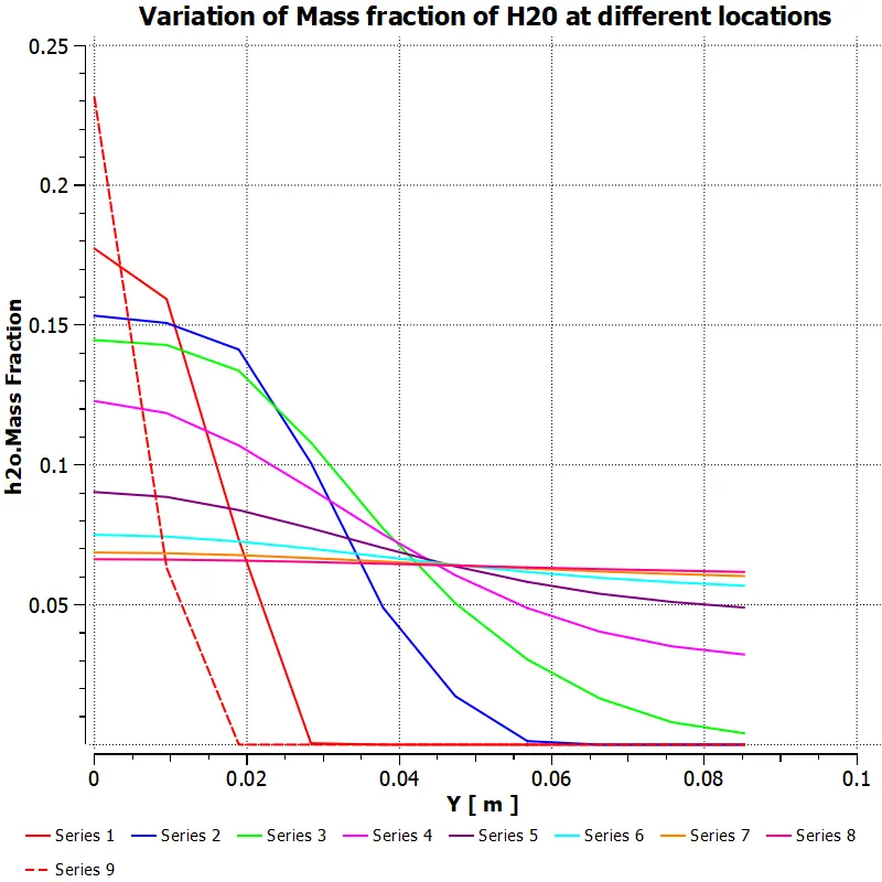
30% of the water in fuel content by mole
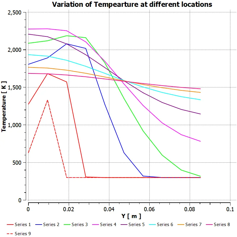
Temperature
5% of the water in fuel content by mole
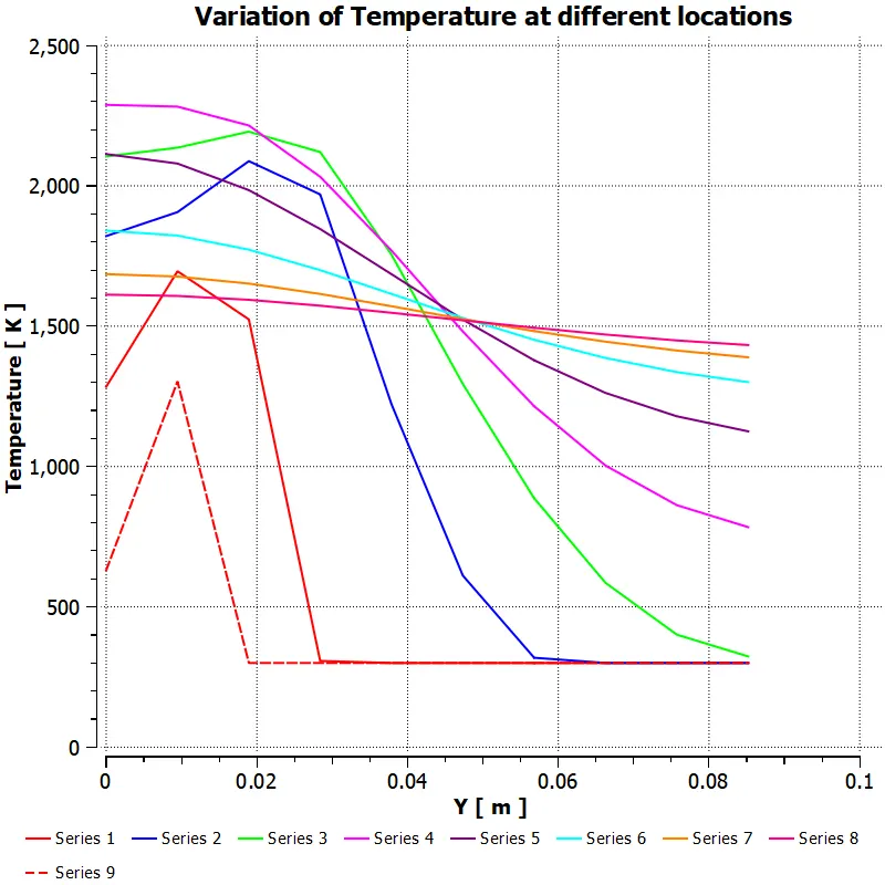
10% of the water in fuel content by mole
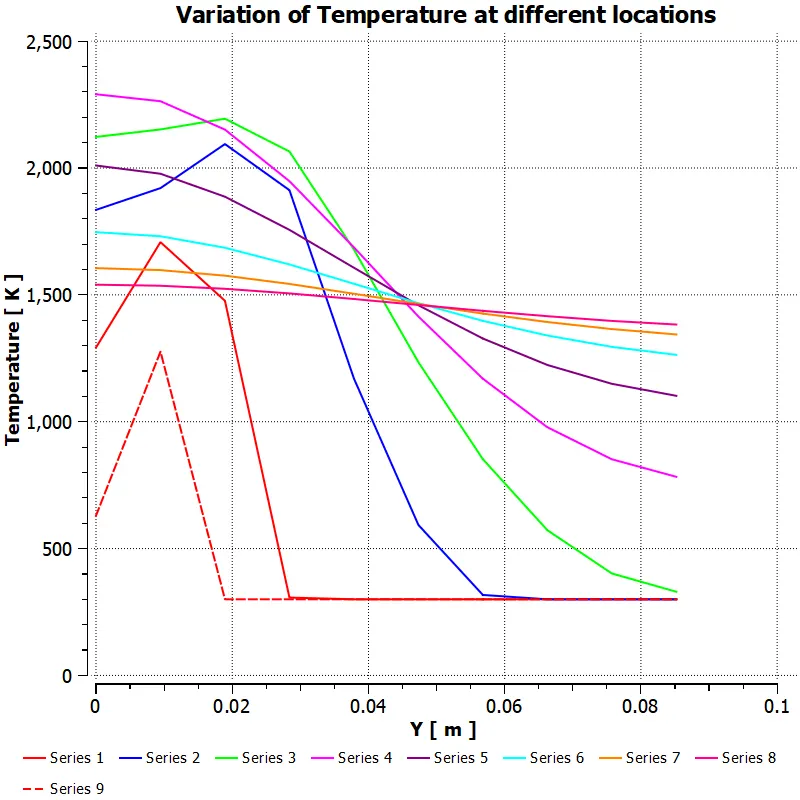
15% of the water in fuel content by mole
20% of the water in fuel content by mole
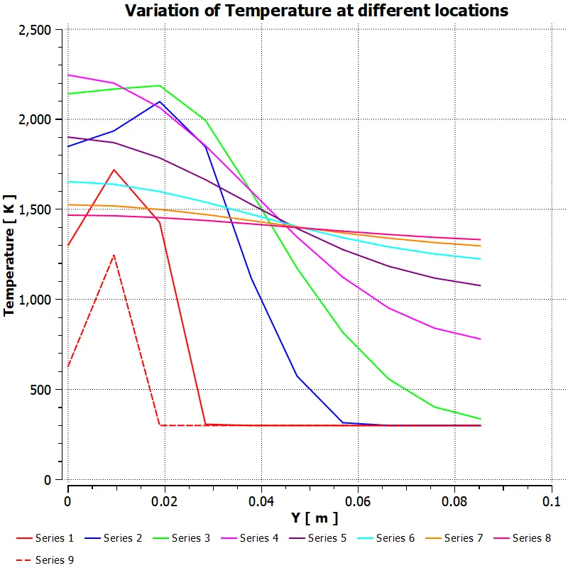
25% of the water in fuel content by mole
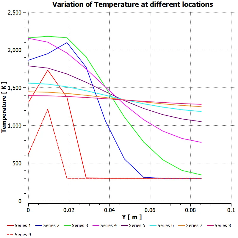
30% of the water in fuel content by mole
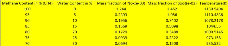
Table:
Graphs:
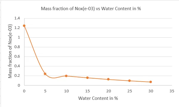
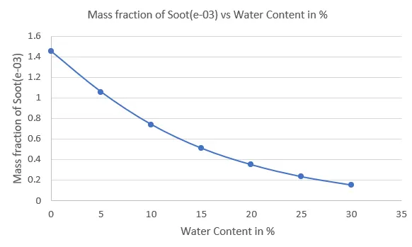
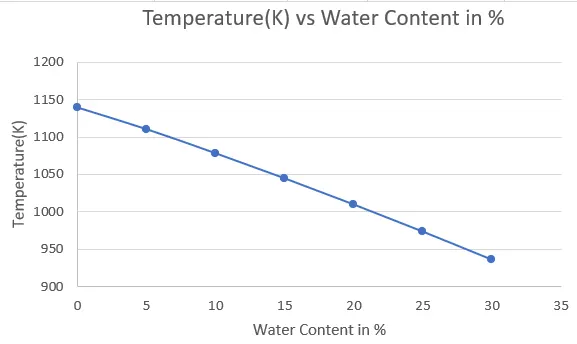
From the simulation that we conducted and looking at the above table we can say that with the addition of water to the fuel, the emission of NOx and Soot got reduced along with this, the overall temperature of the system also got reduced with the addition of water on to the fuel and by increasing the percentage of water, further reduction in the temperature can be observed.
Conclusion:
A steady-state simulation using K epsilon turbulence model was conducted and the results were obtained as desired.
NOx emission level got reduced with the addition of water to the fuel similarly soot emission level and temperature also saw a gradual decrease in its value with the increase in water percentage in the fuel.
Higher the addition of water to fuel, more chances of incomplete combustion
In this challenge, the temperature inside the combustion chamber is analysed. The lines were created and the mass fraction for methane, carbon dioxide, nitrogen, oxygen, water, soot, NOx is analysed in part 1.
In part 2, mass fraction for water, soot, NOx is analysed.
All the contours and graphs have shown a good agreement of results behaviour.