Week 10 - Challenge 3 - Door Trim Lower with Engineering Features
OBJECTIVE
To create the Door Trim Lower Plastic component through the given Class-A surface. To begin with, the tooling axis for the given Class-A Surface should be created meeting the requirements of the draft angle and at the end perform the Draft analysis on the model. Also create the Heat Stakes and the locators considering the design rules.
INTRODUCTION
Plastic components are designed and created from Design model, to Class A surface and further modifications done to create Class B and class C surface thus obtaining the final plastic component. Here, for the door trim, we need to create Class B and Class C surface from the given Class A surface and finally plastic component is created in CATIA workbench (Generative shape design and mechanical part design)
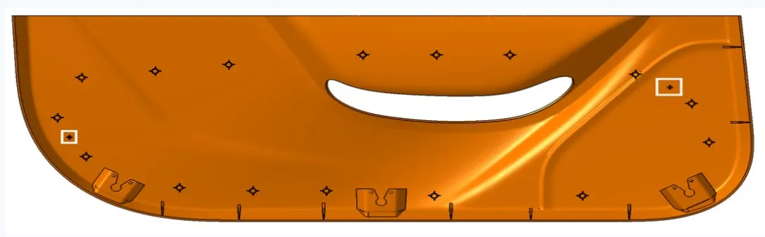
Points for creating Heat stakes and locators are taken from the master section. Engineering features like heat stakes and locators are created in Class B surface meeting the design rules.
DESIGN METHODOLOGY
Class A Surface
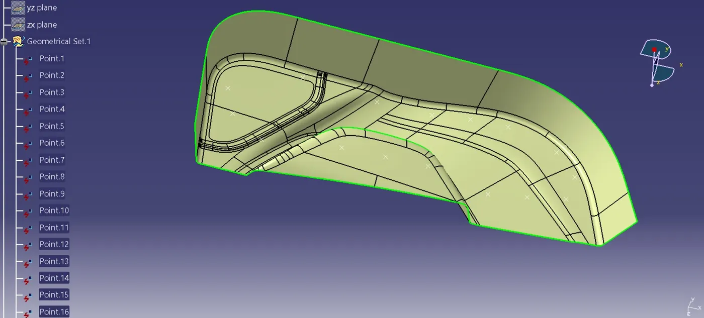
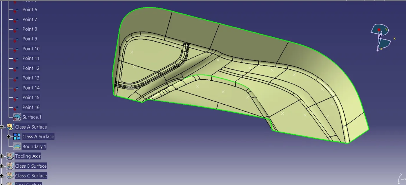
Given input Class A Surface is joined to obtain the Class A Surface of the component to work on and thus obtaining final part model.
Tooling Axis
For any component to manufacture, it needs to clear the draft angle with respect to the tool which it is manufactured. Manufacturability of a component is thus important in the process of making a component to obtain perfect part as well as enhancing the tool life. Tooling axis is the direction in which most of the engineering features can be easily manufactured.
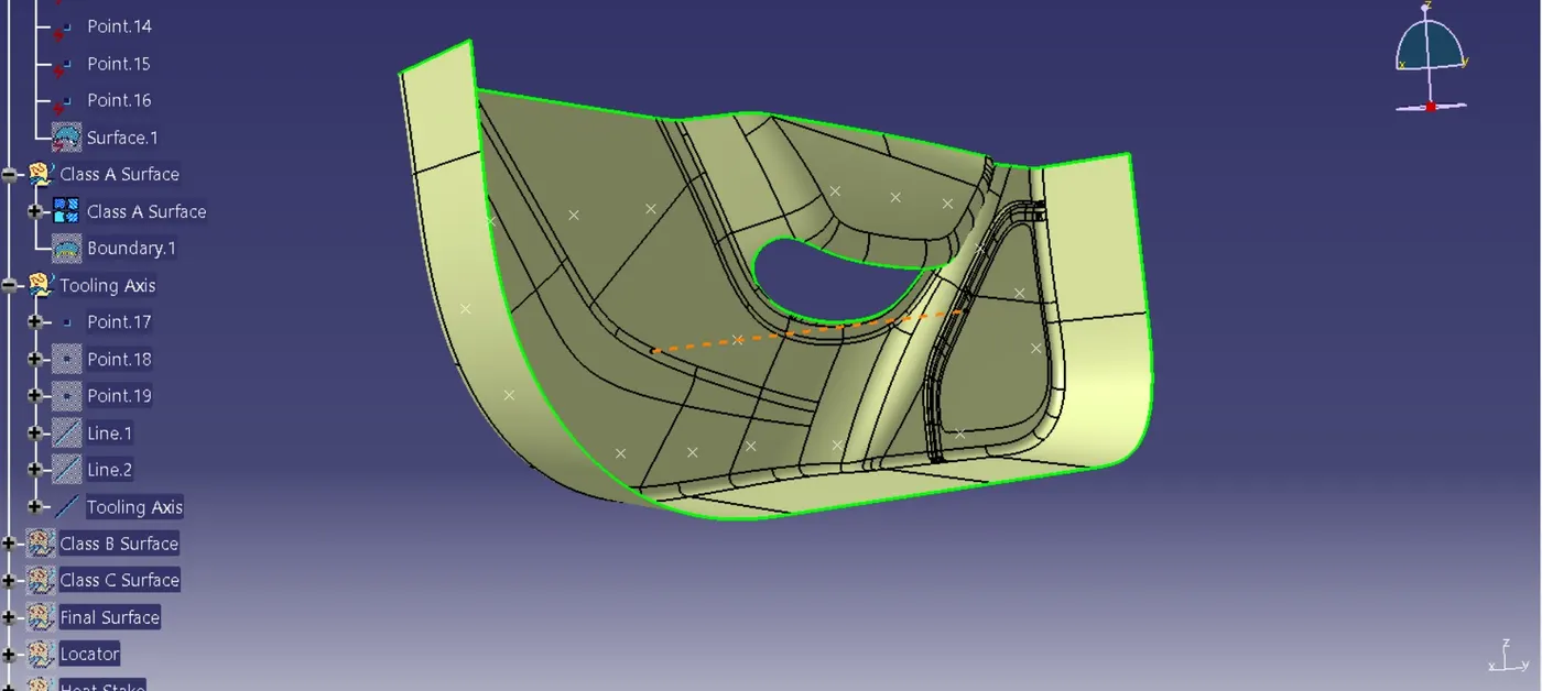
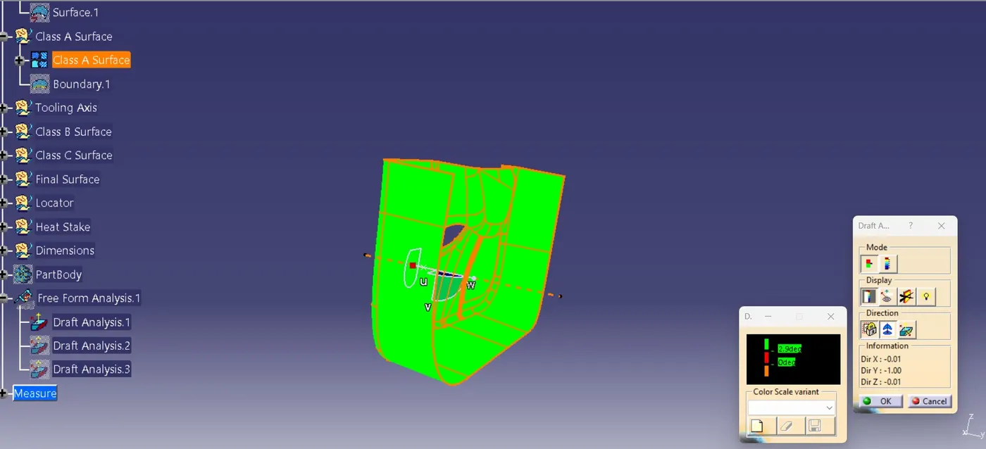
Draft angle for plastic components are 3 degrees, which every component is to be cleared from the resultant draft angle analysis.
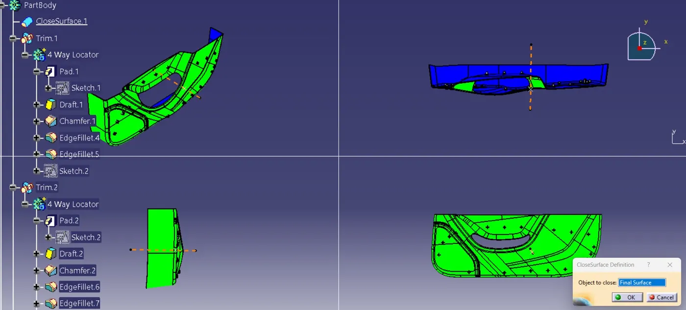
Tooling axis are created from a point on Class A Surface and using bisecting line method. Green color denotes that the component clears positive draft angle analysis performance and blue for negative angle result.
Class B Surface
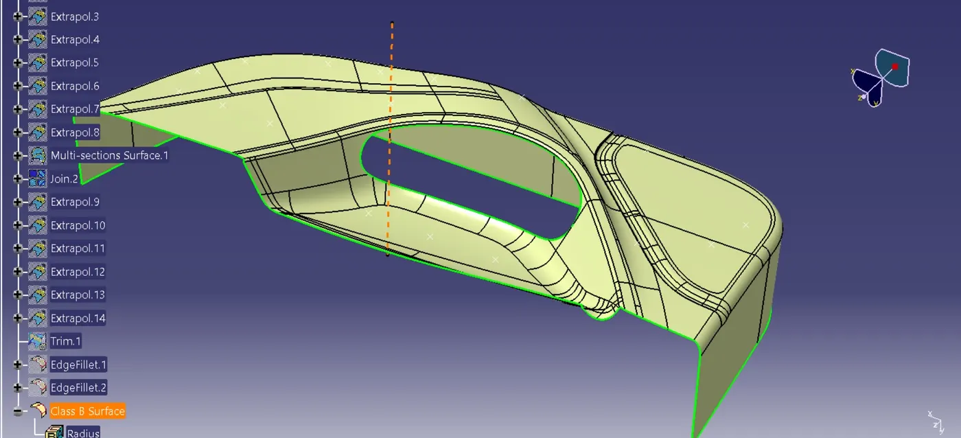
Class B surface is obtained from offsetting Class A surface to a 2.5mm distance.
Class C Surface
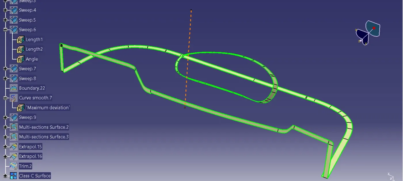
Class C surface is obtained from Class A surface edge and joining the both to obtain a single surface.
Final Surface
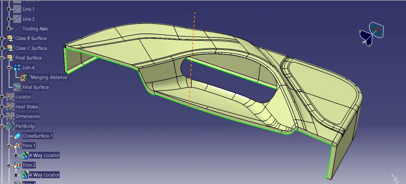
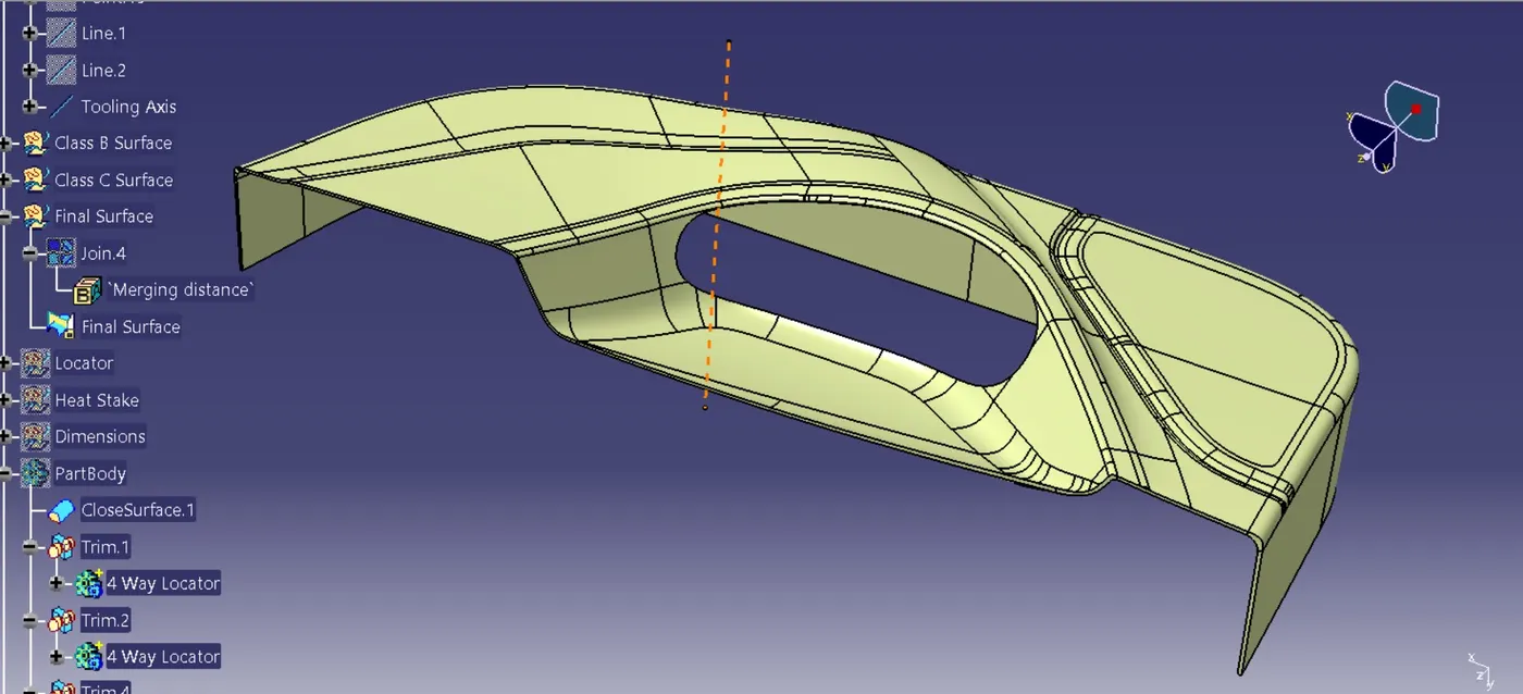
The final plastic surface is thus created by trimming of class B surface and Class A and Class C surface together. Closed surface feature in Catia Surface based feature is used to obtain the final Plastic component.
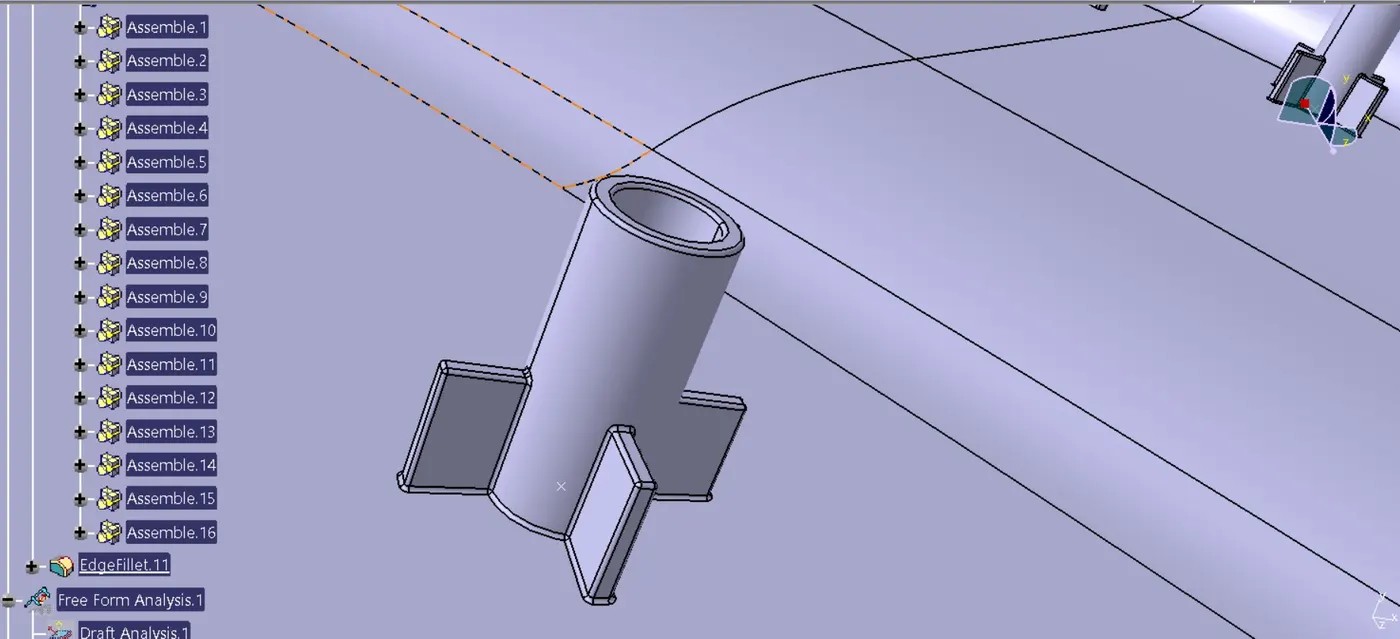
Heat Stakes
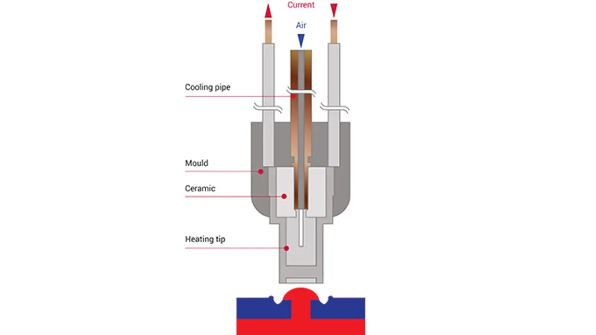
Heat stakes are provided in plastic component to improve performance of fastening with dissimilar material or with plastic component. In heat staking, local heating and cooling is used to raise the temperature of plastic components and reforming of plastic components is thus obtained.
Design Criteria for Heat stakes:
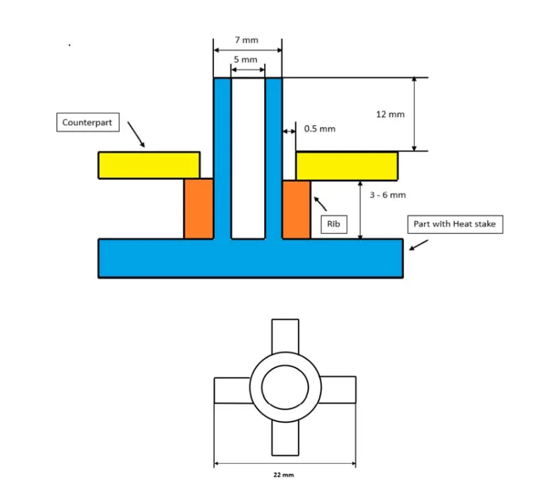
- Length of the Rib - 22 mm
- Height of the Ribs - 3 mm to 6 mm
- Inner Diameter of Heat Stake - 5 mm
- Outer Diameter of Heat Stake - 7 mm
- Minimum clearance between heat stake and counterpart - 0.5 mm
- Minimum fillet of Heat Stakes - 0.25 mm
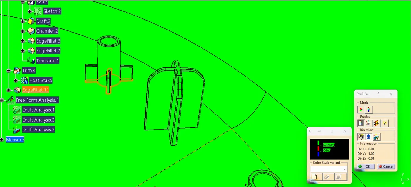
- Minimum Draft Angle of Heat Stakes - 0.5 degrees
Locators
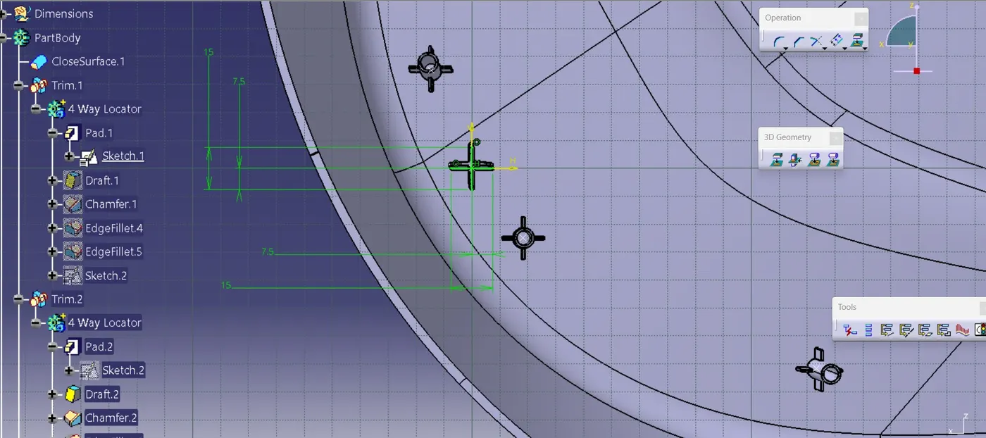
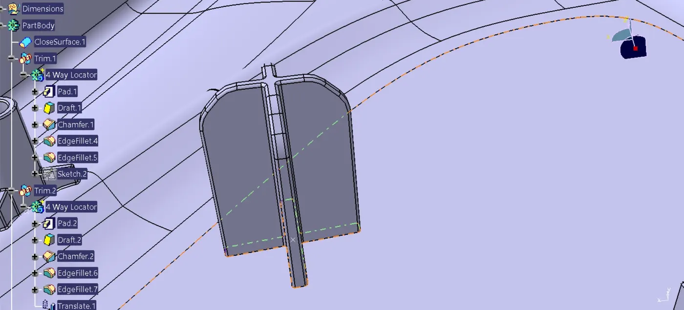
Locators are provided to control the degrees of motion of the component or fix its motion. There are two types of locators, 2-way and 4-way locator. 2-way locator restricts the motion along 1 axis i.e., 2 degrees of freedom. The 4-way pin restricts 4 degrees of freedom along the 2 axis.
Design criteria for locator:
- Height of the locators should be 1 mm (or) 2 mm greater than the heat stakes
- Thickness, fillet and draft angle are of same as rib design rules.
- Ideal Chamfer value - 3 mm x 45 degrees
- Ideal length of the locators - 15 mm
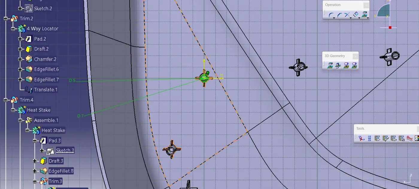
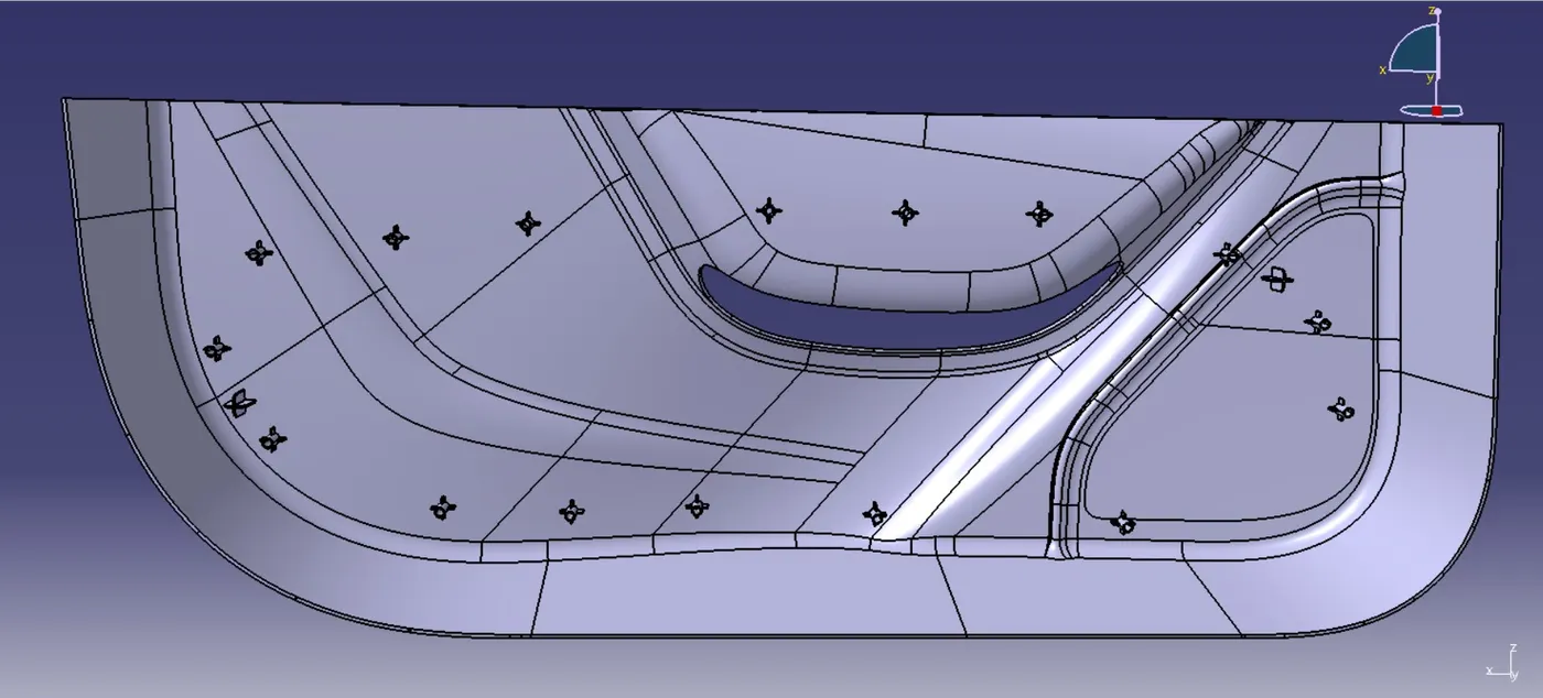
Here in this Door Trim, two 4 way locators are provided to control and fix the component.
DOOR TRIM WITH ENGINEERING FEATURES
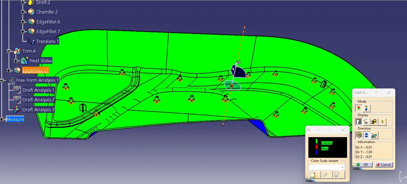
The engineering features, heat stakes and locators are provided according to the reference points in Class B Surface of the plastic component meeting the required design criteria.
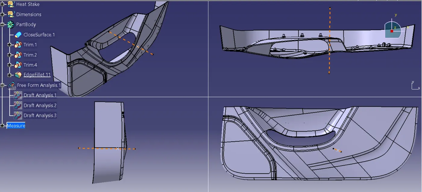
Draft Analysis
Draft analysis of the components were performed before and after providing the engineering features to the components. The draft angle provided for the door trim plastic component was 2.9 degrees, and draft angle for the final component with engineering components provided is 0.45 degrees. Draft analysis is performed to analyze any components manufacturability and tooling there by enhancing the tool life and easy manufacturing and producibility.
CONCLUSION
Door trim with engineering features, Heat stakes and Locators was created in CATIA from given input Class A surface to plastic component meeting all design criteria and manufacturability criteria.