Week 10- Assembly Workbench
ASSEMBLY WORKBENCH
QUICK RETURN MECHANISM AND CV JOINT
AIM:
To create a 3 D Solid CAT Part files using 2 D Sketch, also to solve the sketches with fully (ISO) constrained and also to create a 2 D Drafting sheet from the solid CAT part and Assembly Product with the Frame and Tittle Block
OBJECTIVE:
- To draw the 2-D sketch in CATIA by using the Positioned sketch in Sketcher Workbench.
- To create a Solid CAT Part using Part Workbench with Sketch based feature and Dress up features.
- To create a complete Assembly for Quick Return Mechanism using Assembly Workbench.
- To create a complete Assembly for CV Joint using Assembly Workbench.
- To create a 2D Draft sheet using Drafting workbench.
- To follow the Design standards and to Align the views in a proper way.
- To Import the Frame/Border and Tittle Block in the 2D draft sheet to locate the drawing inside the sheet to guide.
- To Dimensionate the 2D using the feature in the Drafting workbench.
INTRODUCTION:
ASSEMBLY WORKBENCH:
The assembly workbenches use constraints and expressions to create relationships between the objects in model, in order to mathematically tie the objects in place.
The components are brought together and assembled in Assembly Design workbench by applying suitable parametric assembly constraints to them. The assembly constraints allow you to restrict the degrees of freedom of components on their respective work positions. The assembly files in CATIA are called Product files.
CONSTRAINTS:
The constraint is used to arrest the Degeress of Freedom (DOF) along x, y and z axis iin translational and rotational movements. Constraints can also be manually applied after the sketch geometry exists to stabilize sketch shape or position.
TYPES OF CONSTRAINTS:
(1). Dimensional Constraints.
(2). Geometrical Constraints.
(1). DIMENSIONAL CONSTRAINT:
A dimensional constraint is a constraint whose value determines geometric object measurement.
For example:
It control the length of a line, or the distance between two points.
(2). GEOMETRICAL CONSTRAINT:
A geometric constraint is a relationship that forces a limitation between one or more geometric elements.
For example:
A geometric constraint requires that two lines be parallel. If three lines are selected, or two lines and a point, these elements will automatically result parallel to each others.
DRAFTING:
The Drafting is a engineering drawing, graphical representation of structures, machines, and their component parts that communicates the engineering intent of a technical design to the craftsman to makes the product.
PROJECTIONS:
Projection methods are used to represent a 3D object in simple terms so that it can be understood more easily. It’s used in mechanical drawing and design so that the structure created by a designer can be communicated to manufacturers.
FRAMES AND TITTLE BLOCK:
A border/ Frame is a line drawn around the inside edge of the paper. It is basically a rectangle drawn precisely and inside this rectangle is the design area.
A title block is comprised of the information boxes found on the bottom right- hand corner of a drawing, which indicate drawing details such as the title, author name, scale, and date the drawing was created and informations.
POSITIONED SKETCH:
A Positioned Sketch is a sketch that has its origin location or orientation defined with construction geometry. As the construction geometry changes the sketch position or orientation will change accordingly.
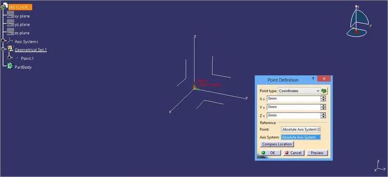
A positioned sketch is being able to define the sketch support, sketch origin and sketch orientation. In the co-ordinates the point is defined at the center of the axis (x,y,z).
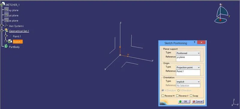
After defined the point into the axis the sketch position is to be defined in order to select the plane to create a sketch. In the planer support the type is seleceted as positioned and the reference are selected based on the geometry. The origin type is selected as projection point in which the defined point are selected based on the references.
CREATING 3 -D CAT PART - SKETCH BASED FEATURES - QUICK RETURN MECHANISM
QUICK RETURN MECHANISM -BODY -1:
ISO CONSTRAIN SKETCH:
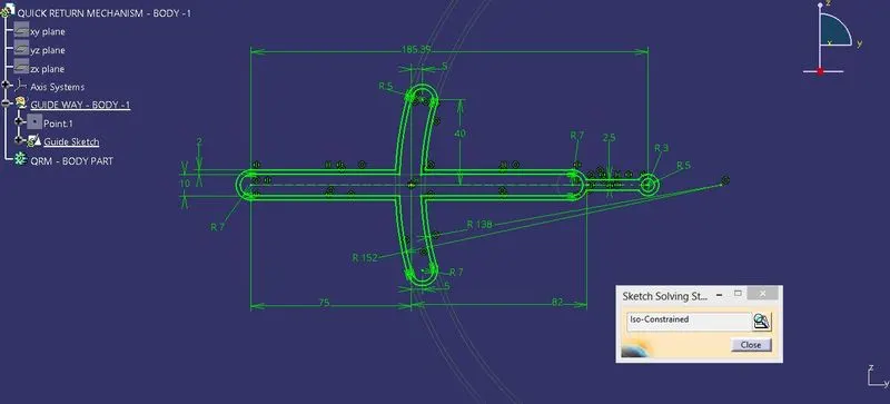
All the degrees of freedom of a geometry have been taken up by a consistent combination of dimensions and fixed geometry, that geometry is said to be iso-constrained/ fully defined.
In two dimensions, points and lines have two degrees of freedom, circles have three and ellipses have five degrees of freedom. Fixed geometry will never be moved, and has no degree of freedom. Arresting all DOF from the origin then the sketch will be iso constrained.
PAD FEATURE:
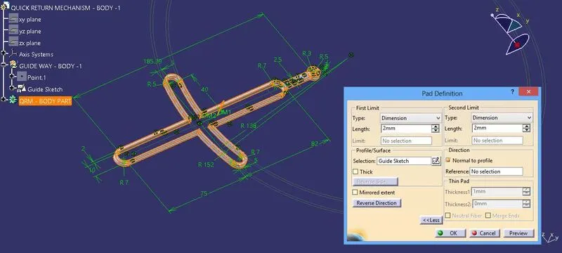
Pad command is a 3D sketching tool that allows to create sketches to extrude on the defined range of dimensions. Creating a pad means extruding a profile or a surface in one or two directions. The application lets choose the limits of creation as well as the direction of extrusion. By using a 2D closed profile, the Dimension and Mirrored extent options the extrusion as been done.
2 -D DRAFT SHEET:
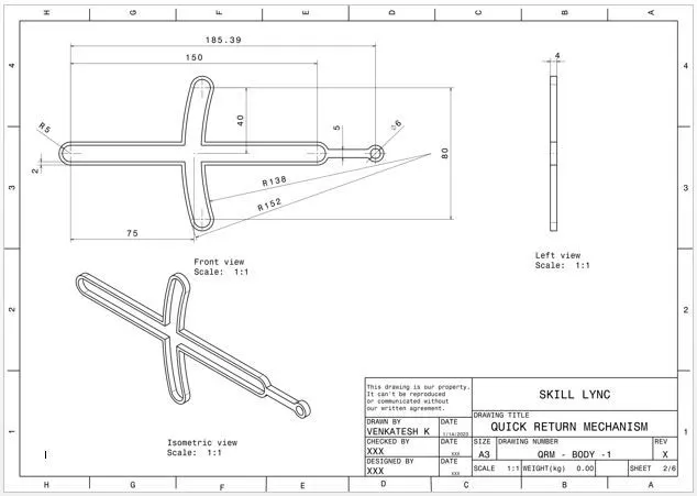
By using the Drafing Workbench the Quick Return Mechanism- Body -1 are drafted in Front View, Isometric view, Side view and Top View and using the detailed view the complex dimensions are scaled and Dimensioned in a proper way.
QUICK RETURN MECHANISM -BODY -2:
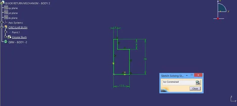
ISO CONSTRAIN SKETCH:
All the degrees of freedom of a geometry have been taken up by a consistent combination of dimensions and fixed geometry, that geometry is said to be iso-constrained/ fully defined.
In two dimensions, points and lines have two degrees of freedom, circles have three and ellipses have five degrees of freedom. Fixed geometry will never be moved, and has no degree of freedom. Arresting all DOF from the origin then the sketch will be iso constrained.
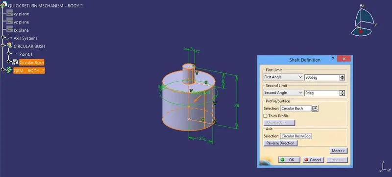
SHAFT FEATURE:
The shaft command in the sketch based feature is used to revolve the profile along the axis of rotation. The Profile as been created in the part and based on the axis the Shaft is done on the profile.
2 -D DRAFT SHEET:
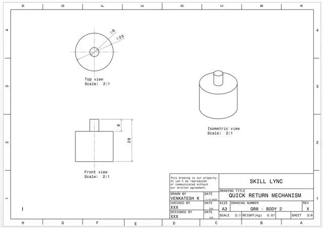
By using the Drafing Workbench the Quick Return Mechanism- Body -2 are drafted in Front View, Isometric view, Side view and Top View and using the detailed view the complex dimensions are scaled and Dimensioned in a proper way.
QUICK RETURN MECHANISM -BODY -3:
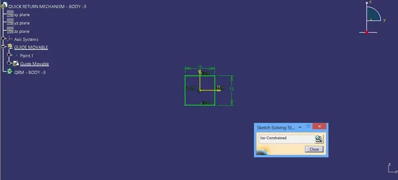
ISO CONSTRAIN SKETCH:
All the degrees of freedom of a geometry have been taken up by a consistent combination of dimensions and fixed geometry, that geometry is said to be iso-constrained/ fully defined.
In two dimensions, points and lines have two degrees of freedom, circles have three and ellipses have five degrees of freedom. Fixed geometry will never be moved, and has no degree of freedom. Arresting all DOF from the origin then the sketch will be iso constrained.
PAD FEATURE:
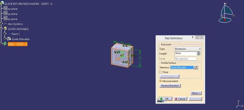
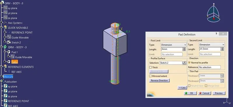
Pad command is a 3D sketching tool that allows to create sketches to extrude on the defined range of dimensions. Creating a pad means extruding a profile or a surface in one or two directions. The application lets choose the limits of creation as well as the direction of extrusion. By using a 2D closed profile, the Dimension and Mirrored extent options the extrusion as been done.
2 -D DRAFT SHEET:
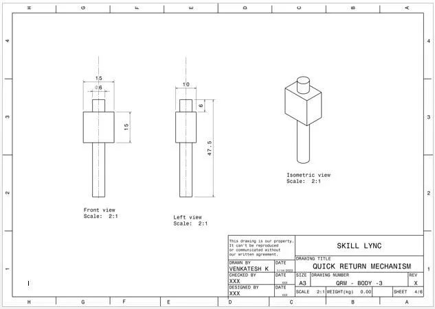
By using the Drafing Workbench the Quick Return Mechanism- Body -3 are drafted in Front View, Isometric view, Side view and Top View and using the detailed view the complex dimensions are scaled and Dimensioned in a proper way.
QUICK RETURN MECHANISM -BODY -4:
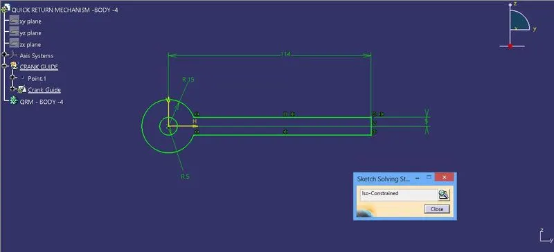
ISO CONSTRAIN SKETCH:
All the degrees of freedom of a geometry have been taken up by a consistent combination of dimensions and fixed geometry, that geometry is said to be iso-constrained/ fully defined.
In two dimensions, points and lines have two degrees of freedom, circles have three and ellipses have five degrees of freedom. Fixed geometry will never be moved, and has no degree of freedom. Arresting all DOF from the origin then the sketch will be iso constrained.
PAD FEATURE:
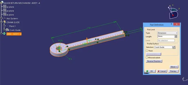
Pad command is a 3D sketching tool that allows to create sketches to extrude on the defined range of dimensions. Creating a pad means extruding a profile or a surface in one or two directions. The application lets choose the limits of creation as well as the direction of extrusion. By using a 2D closed profile, the Dimension and Mirrored extent options the extrusion as been done.
2 -D DRAFT SHEET:
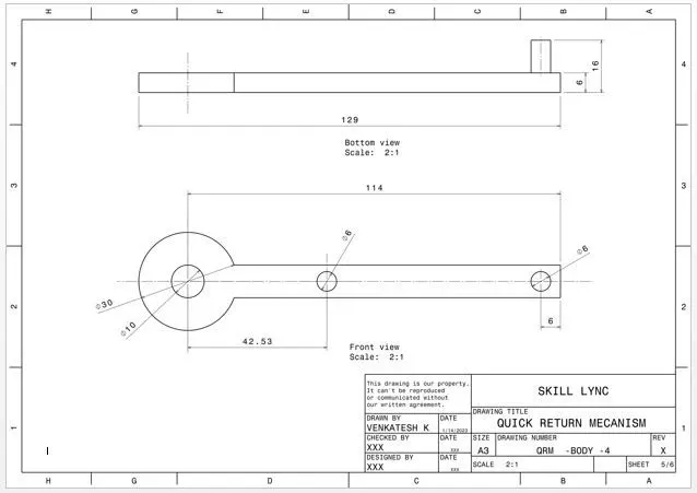
By using the Drafing Workbench the Quick Return Mechanism- Body -4 are drafted in Front View, Isometric view, Side view and Top View and using the detailed view the complex dimensions are scaled and Dimensioned in a proper way.
QUICK RETURN MECHANISM -BODY -5:
ISO CONSTRAIN SKETCH:
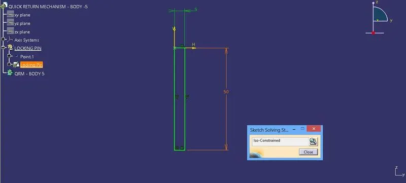
All the degrees of freedom of a geometry have been taken up by a consistent combination of dimensions and fixed geometry, that geometry is said to be iso-constrained/ fully defined.
In two dimensions, points and lines have two degrees of freedom, circles have three and ellipses have five degrees of freedom. Fixed geometry will never be moved, and has no degree of freedom. Arresting all DOF from the origin then the sketch will be iso constrained.
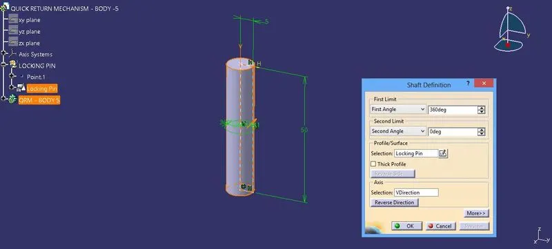
SHAFT FEATURE:
The shaft command in the sketch based feature is used to revolve the profile along the axis of rotation. The Profile as been created in the part and based on the axis the Shaft is done on the profile.
2 -D DRAFT SHEET:
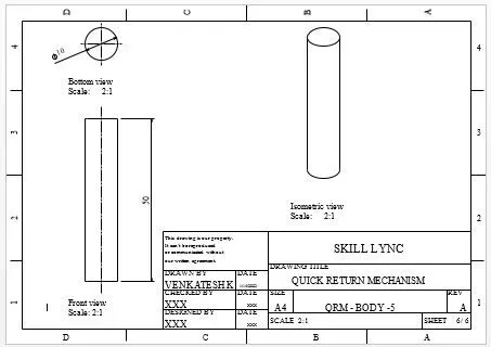
By using the Drafing Workbench the Quick Return Mechanism- Body -5 are drafted in Front View, Isometric view, Side view and Top View and using the detailed view the complex dimensions are scaled and Dimensioned in a proper way.
QUICK RETURN MECHANISM - ASSEMBLY
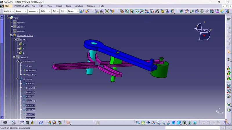
CREATING REFERENCE PARENT:
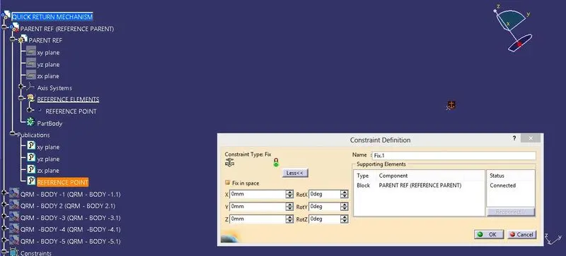
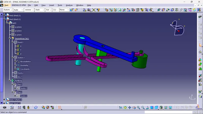
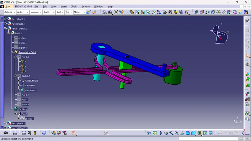
In the Assembly Workbech, THe reference skelton/ parent planes and Reference points are been created, in which by using the excesting part features the created solid CAT Parts are been gathered together in an assembly Workbenchs.
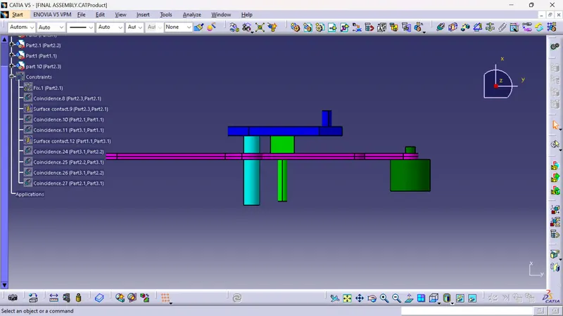
By using the Fix Constraint the reference points are been fixed by which all the DOF are been arrested, preventing this component from moving from its parents during the update operation. The component is fixed by selecting one of its geometrical element at least.
COINCIDE CONSTRAINT:
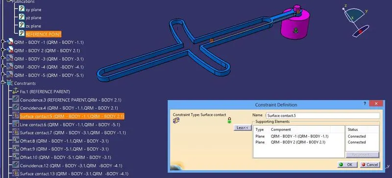
Coincidence constraints are used to align elements. Depending on the selected elements, you may obtain concentricity, coaxiality or coplanarity. By which the Axis are been selecetd andconstrained accordingly.
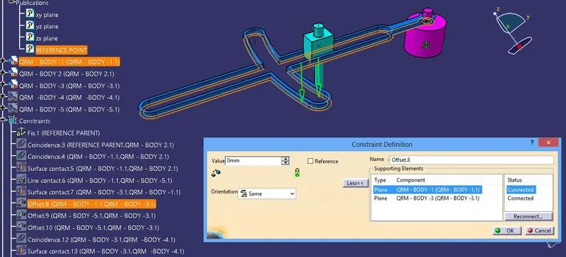
OFFSET CONSTRAINT:
An offset constraint between two components, need to specify how faces should be oriented. The offset value is always displayed next to the offset constraint AND PROVIDED THE RESPECTIVE DIMENSIONS.
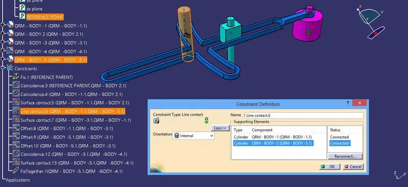
LINE AND SURFACE CONSTRAINT:
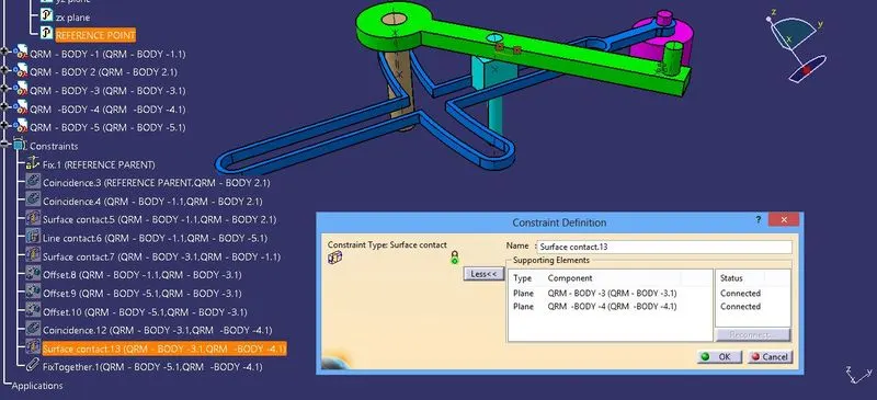
Contact type constraints can be created between two planes or faces. The common area between the two planes can be a plane (plane contact), a line (line contact) or a point (point contact).
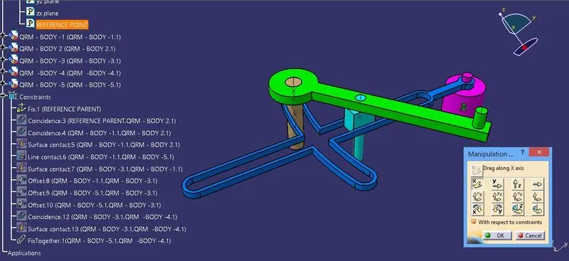
MANIPULATOR:
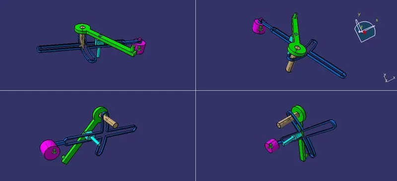
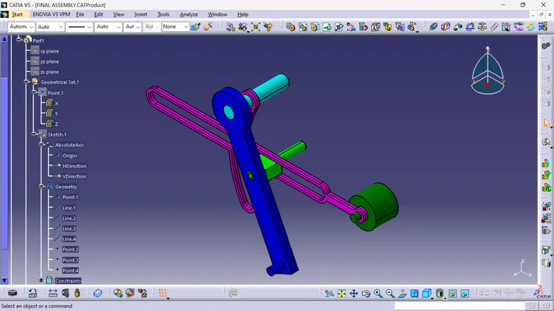
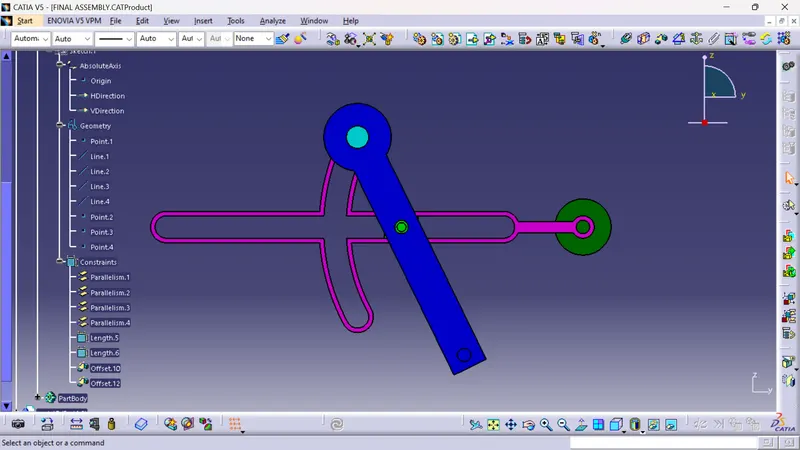
After assembling all the part files in Quick return Mechanism by using the manipulator with respect to constrain all the axis are been manipulated with respect to each other.
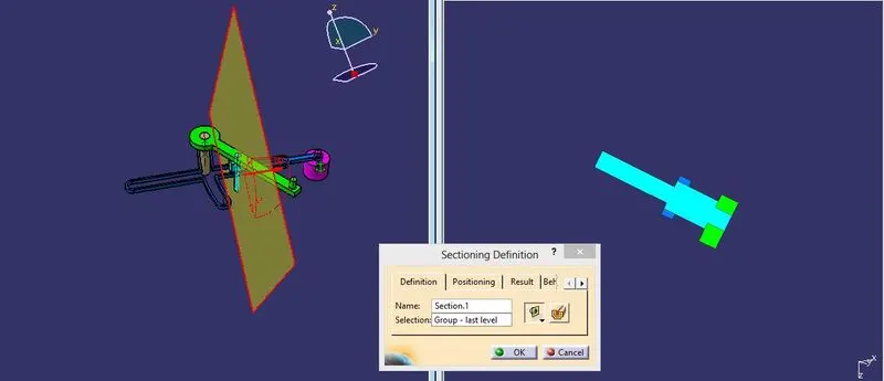
SECTION:
By using the section definition the assembled product areeb sectioned along the positioning on the part files and displayed accordingly.
ISOMETRIC VIEW, FRONT VIEW, SIDE VIEW AND BOTTOM VIEW:
2 -D DRAFT SHEET:
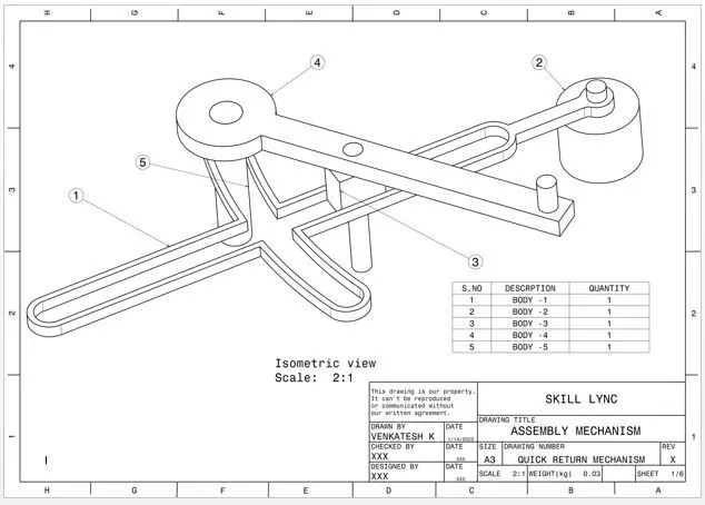
By using the Drafing Workbench the Quick Return Mechanism- ASSEMBLY are drafted in Isometric view using the detailed view the complex dimensions are scaled and Dimensioned in a proper way.
-----------------------------------------------------------------------------------------------------------------------------------------------------------
CREATING 3 -D CAT PART - SKETCH BASED FEATURES - CV JOINT
CV JOINT -BODY -1:
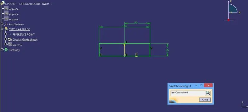
ISO CONSTRAIN SKETCH:
All the degrees of freedom of a geometry have been taken up by a consistent combination of dimensions and fixed geometry, that geometry is said to be iso-constrained/ fully defined.
In two dimensions, points and lines have two degrees of freedom, circles have three and ellipses have five degrees of freedom. Fixed geometry will never be moved, and has no degree of freedom. Arresting all DOF from the origin then the sketch will be iso constrained.
SHAFT FEATURE:
The shaft command in the sketch based feature is used to revolve the profile along the axis of rotation. The Profile as been created in the part and based on the axis the Shaft is done on the profile.
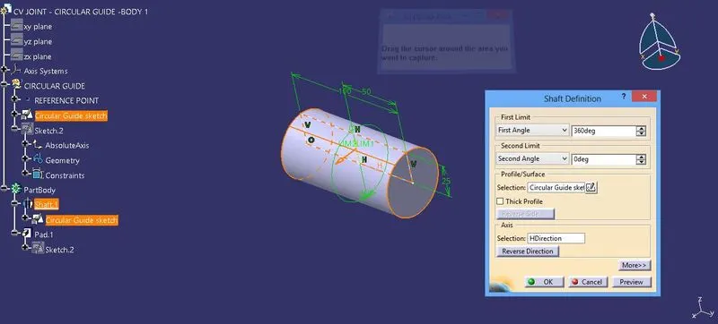
CIRCULAR SKETCH:
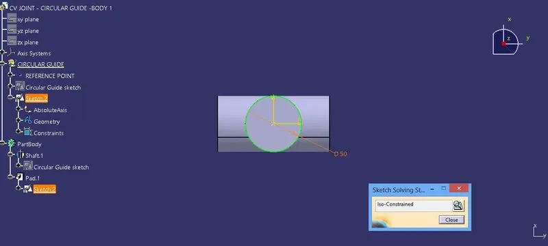
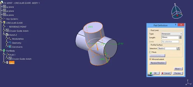
PAD FEATURE:
Pad command is a 3D sketching tool that allows to create sketches to extrude on the defined range of dimensions. Creating a pad means extruding a profile or a surface in one or two directions. The application lets choose the limits of creation as well as the direction of extrusion. By using a 2D closed profile, the Dimension and Mirrored extent options the extrusion as been done.
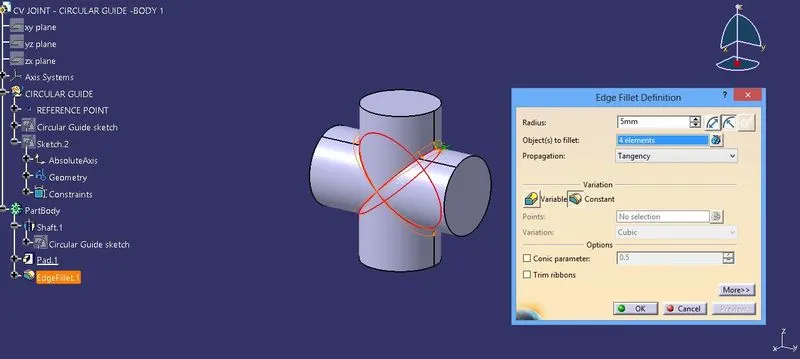
By using the Dress Up Fetaures the edges are been selected and filleted @ the respective fillet radii.
2 -D DRAFT SHEET:
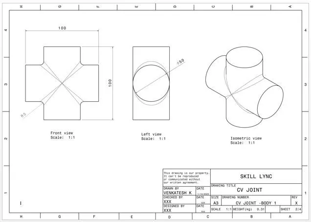
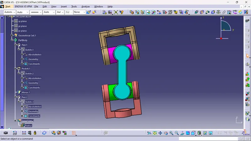
By using the Drafing Workbench the CV JOINT- Body -1 are drafted in Front View, Isometric view, Side view and Top View and using the detailed view the complex dimensions are scaled and Dimensioned in a proper way.
CV JOINT -BODY -2:
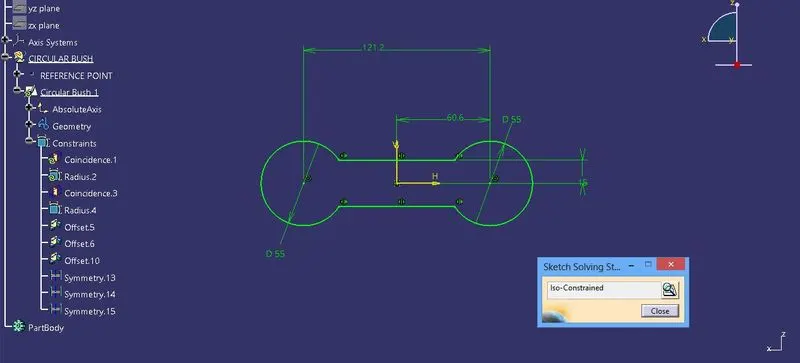
ISO CONSTRAIN SKETCH:
All the degrees of freedom of a geometry have been taken up by a consistent combination of dimensions and fixed geometry, that geometry is said to be iso-constrained/ fully defined.
In two dimensions, points and lines have two degrees of freedom, circles have three and ellipses have five degrees of freedom. Fixed geometry will never be moved, and has no degree of freedom. Arresting all DOF from the origin then the sketch will be iso constrained.
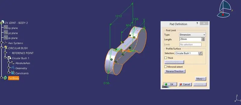
PAD FEATURE:
Pad command is a 3D sketching tool that allows to create sketches to extrude on the defined range of dimensions. Creating a pad means extruding a profile or a surface in one or two directions. The application lets choose the limits of creation as well as the direction of extrusion. By using a 2D closed profile, the Dimension and Mirrored extent options the extrusion as been done.
POCKET FEATURE:
Pocket tool is used to remove the material from any part of the Element. The prepared solid model by using “PAD” tool and to remove the unwanted material “POCKET” will be used.
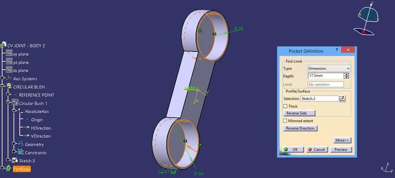
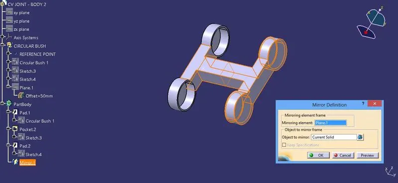
By using the plane definition the respective planes are been offseted to the respective distance and using the Mirror feature the solid part are been Mirrored with respect to the plane axis.
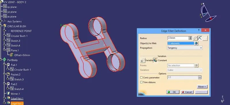
By using the Dress Up Fetaures the edges are been selected and filleted @ the respective fillet radii.
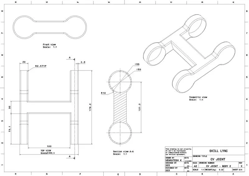
2 -D DRAFT SHEET:
CV JOINT- BODY -3:
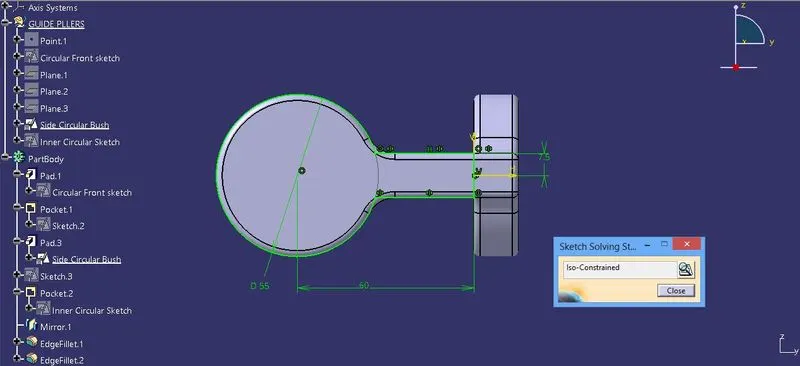
ISO CONSTRAIN SKETCH:
All the degrees of freedom of a geometry have been taken up by a consistent combination of dimensions and fixed geometry, that geometry is said to be iso-constrained/ fully defined.
In two dimensions, points and lines have two degrees of freedom, circles have three and ellipses have five degrees of freedom. Fixed geometry will never be moved, and has no degree of freedom. Arresting all DOF from the origin then the sketch will be iso constrained.
POCKET FEATURE:
Pocket tool is used to remove the material from any part of the Element. The prepared solid model by using “PAD” tool and to remove the unwanted material “POCKET” will be used.
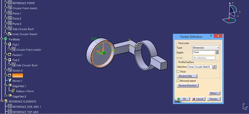
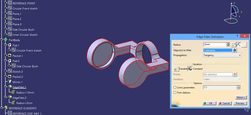
By using the plane definition the respective planes are been offseted to the respective distance and using the Mirror feature the solid part are been Mirrored with respect to the plane axis. By using the Dress Up Fetaures the edges are been selected and filleted @ the respective fillet radii.
2 -D DRAFT SHEET:
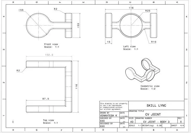
By using the Drafing Workbench the CV JOINT Body -3 are drafted in Front View, Isometric view, Side view and Top View and using the detailed view the complex dimensions are scaled and Dimensioned in a proper way.
CV JOINT - ASSEMBLY
CREATING REFERENCE PARENT:
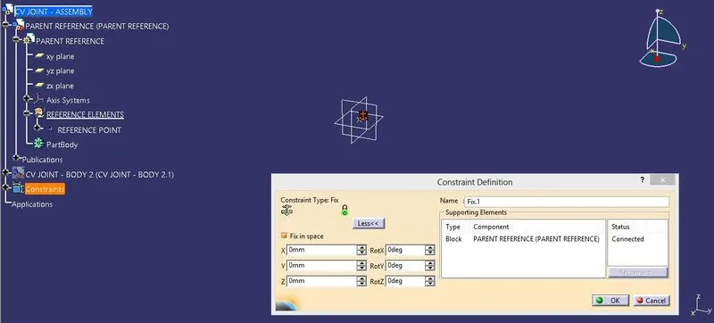
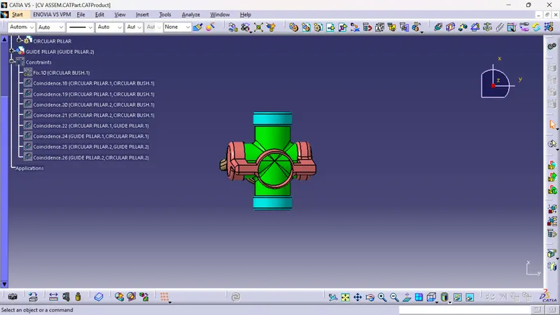
In the Assembly Workbech, THe reference skelton/ parent planes and Reference points are been created, in which by using the excesting part features the created solid CAT Parts are been gathered together in an assembly Workbenchs.
By using the Fix Constraint the reference points are been fixed by which all the DOF are been arrested, preventing this component from moving from its parents during the update operation. The component is fixed by selecting one of its geometrical element at least.
COINCIDE CONSTRAINT:
Coincidence constraints are used to align elements. Depending on the selected elements, you may obtain concentricity, coaxiality or coplanarity. By which the Axis are been selecetd andconstrained accordingly.
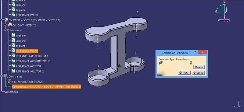
Coincidence constraints are used to align elements. Depending on the selected elements, you may obtain concentricity, coaxiality or coplanarity. By which the Axis are been selecetd and constrained accordingly.
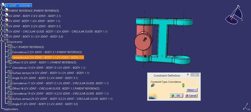
SURFACE CONSTRAINT:
Contact type constraints can be created between two planes or faces. The common area between the two planes can be a plane (plane contact), a line (line contact) or a point (point contact).
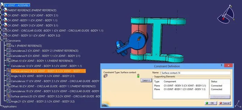
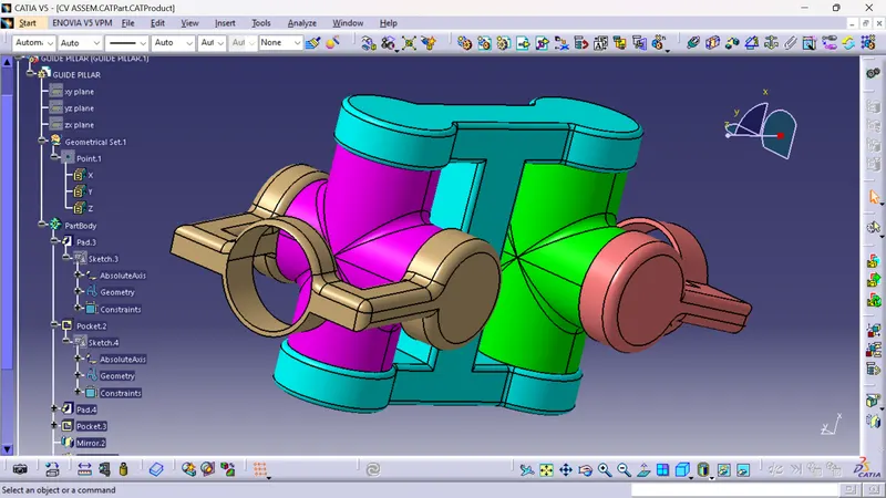
MANIPULATOR:
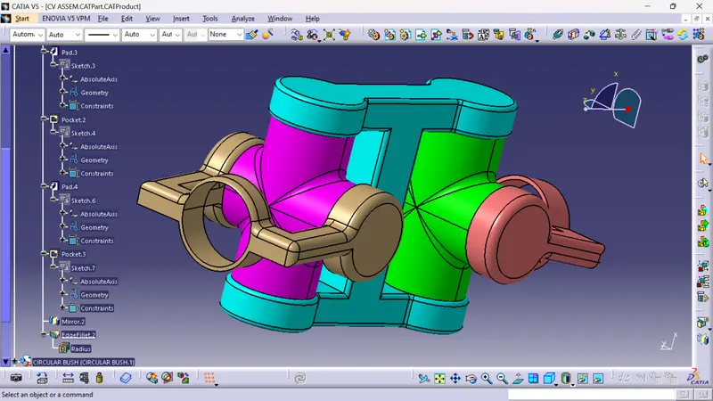
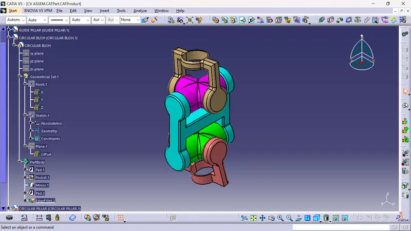
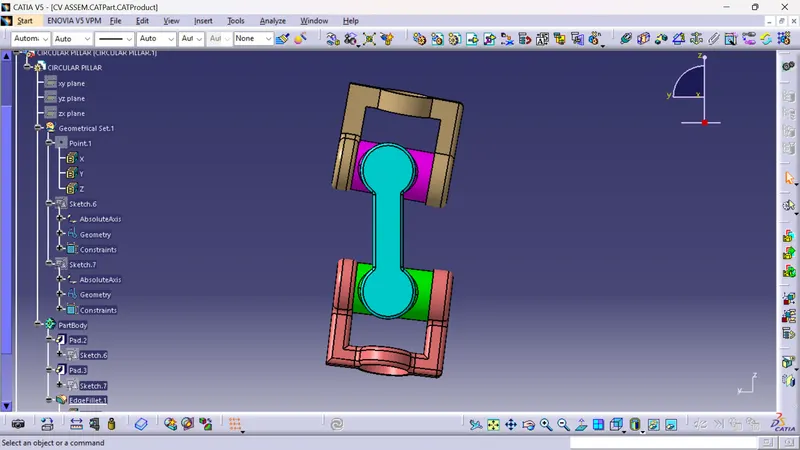
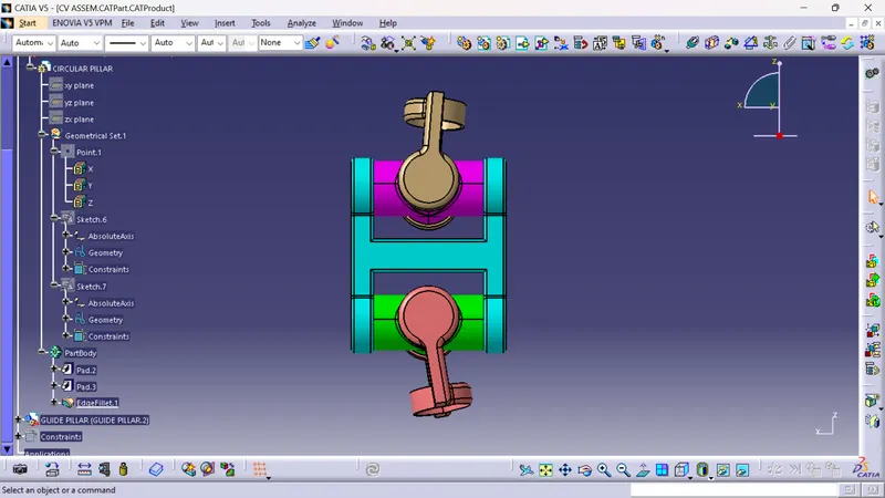
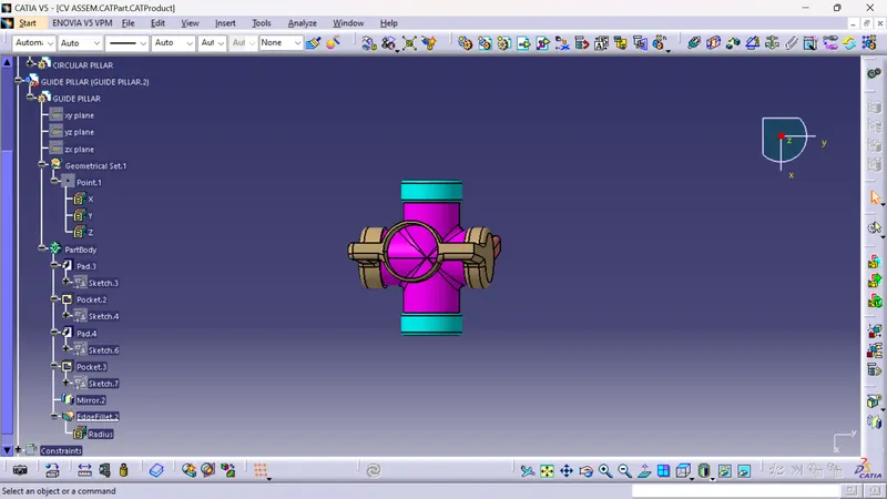
After assembling all the part files in CV JOINT by using the manipulator with respect to constrain all the axis are been manipulated with respect to each other. As same as all the constraints are been Given to the another cv joints as well.
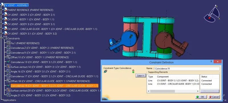
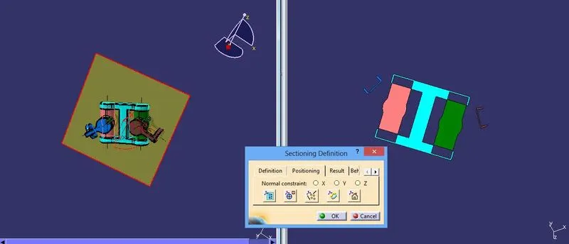
SECTION:
By using the section definition the assembled product are sectioned along the positioning on the part files and displayed accordingly.
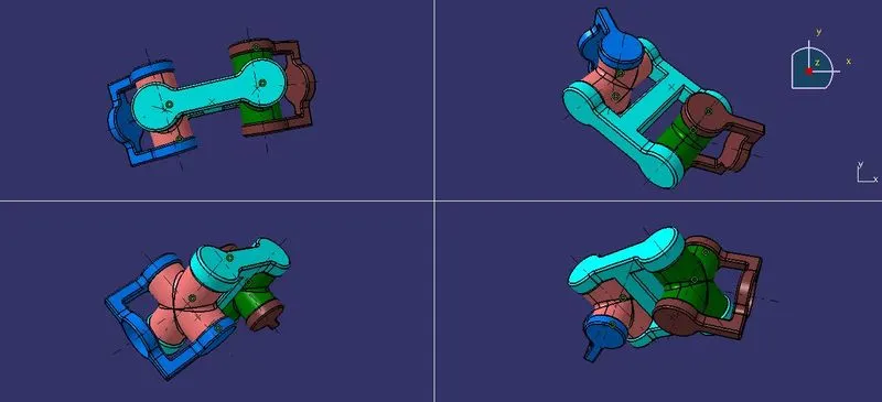
ISOMETRIC VIEW, FRONT VIEW, SIDE VIEW AND BOTTOM VIEW:
2 -D DRAFT SHEET:
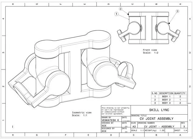
By using the Drafing Workbench the CV JOINT- ASSEMBLY are drafted in Front View, Isometric view using the detailed view the complex dimensions are scaled and Dimensioned in a proper way.
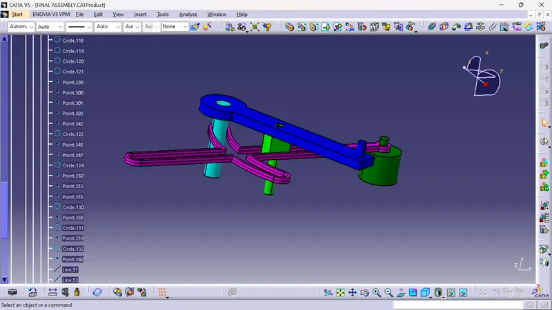
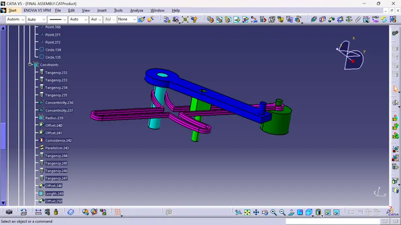
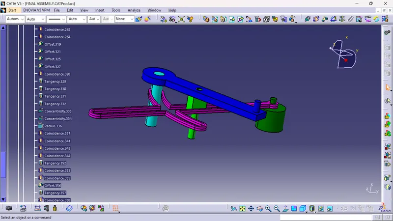
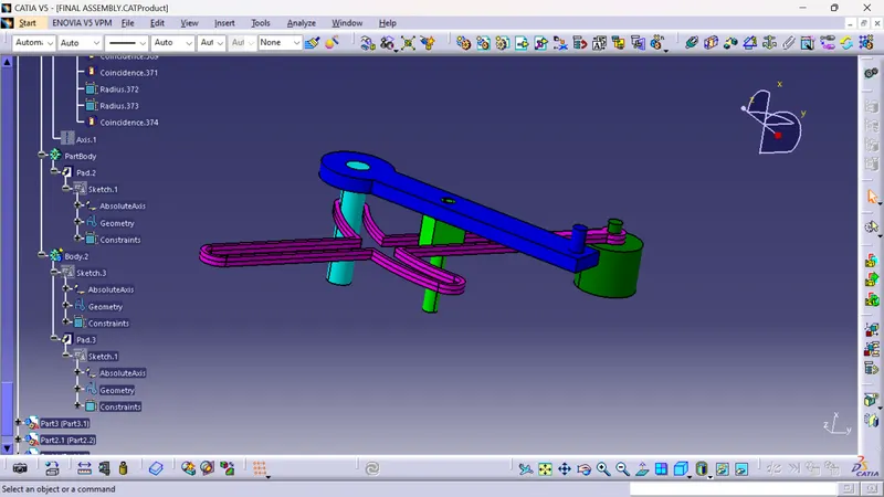
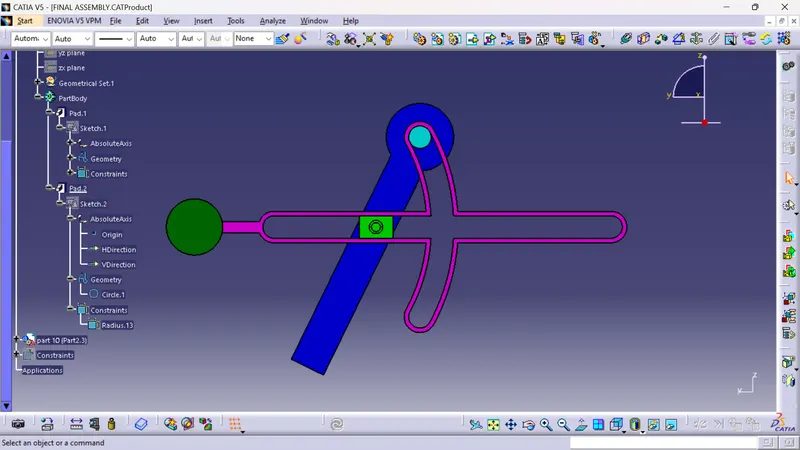
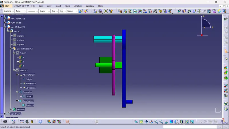
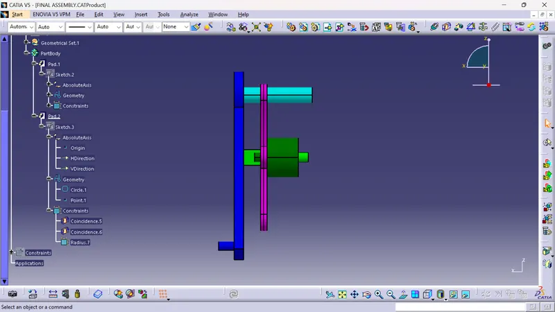
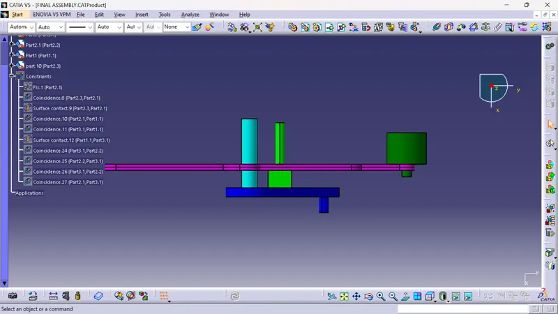
CV JOINT
VIEWS
CONCLUSION:
- The 2-D sketch of the drawing are drawn using CATIA SKETCHER workbench and are fuly constrained.
- The Positioned sketch has been used and 2D sketches are drawn with respect to referece plane and screenshots of the Fully Defined Sketch with sketch solving status bar dialog box showing Iso-Constrained are attached.
- The creation of complete Assembly for Quick Return Mechanism using Assembly Workbench are assembled.
- The creation of complete Assembly for CV Joint using Assembly Workbench are assembled.
- The 3D Assembled Product Model with various orientations are attached.
- The 2D Drafting sheet using Drafting workbench are created.
- The Design standards and the views are aliged in a proper way.
- The Frame/Border and Tittle Block in the 2D draft sheet to locate the drawing inside the sheet to guide path are imported.
- The switching between Background and working Views are utilized and Imported Blocks.
- The 2 D Draft sheeet are Dimensineoted with the help of features in Drafting Workbench.