Wiring harness design in CATIA V5 - 3D modeling Week 4 Challenge
AIM:
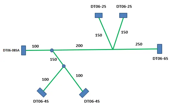
Route the following harness layout in Electrical workbench. Make assumption for harness bundle diameters. Use Following connectors as shown in layout diagram.
Add protective covering on all branches connected to DT06-2S & DT06-4S connectors. Keep end extremity at 30mm (from connectors end)
Download connector 3D data from www.te.com
- DT06-4S
- DT06-6S
- DT06-2S
- DT06-08SA
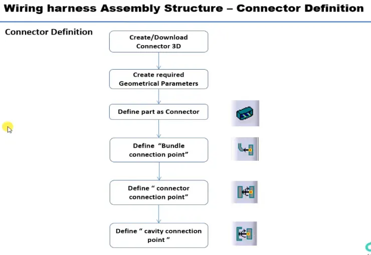
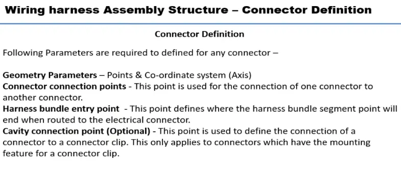
CONNECTOR DEFINATIONS IN CATIA V5
1. Deutsch DT06 – 08SA
Connector connection point:
Create midpoint on the contact face which will be normal to wire bunddle insertion.
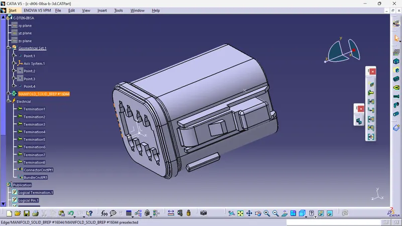
Craete Axis System with respect to the point which we have created and defining the axis direction as shown below,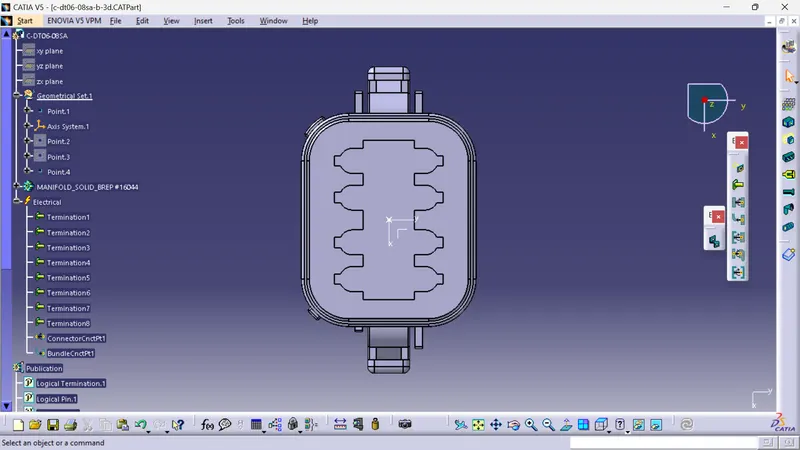
Bundle connection point:
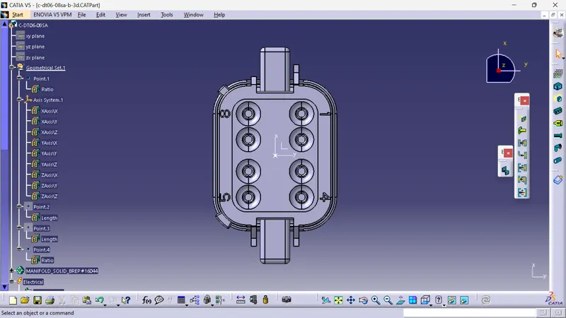
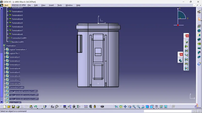
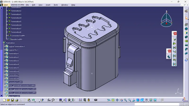
Switch to 'Electric Part Design'
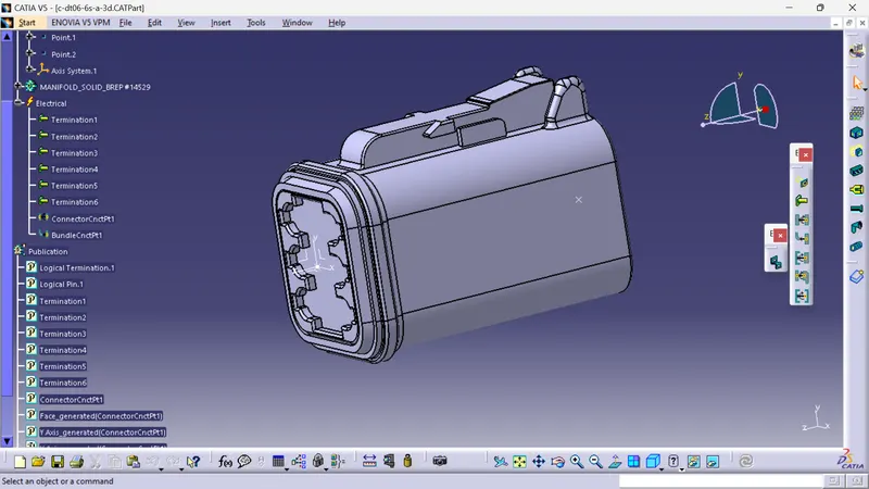
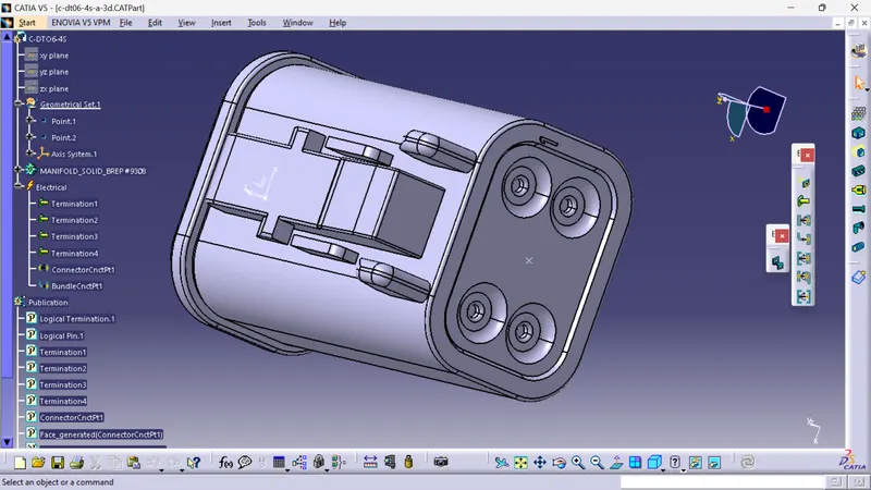
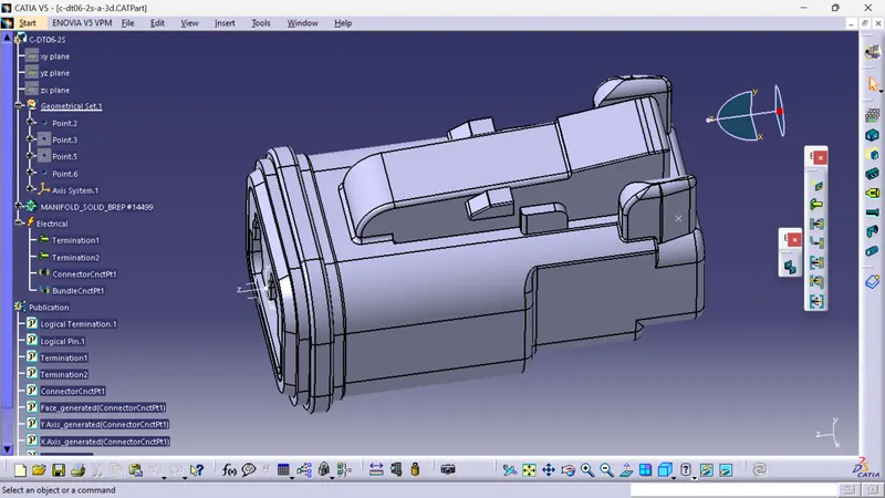
Define the part as connector in catia, give no. of termination as 8 because we have 8 entry points for wire.
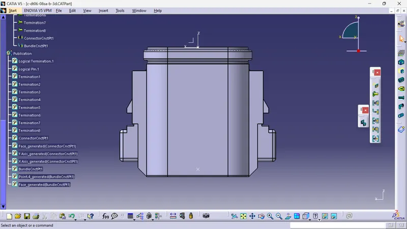
Define connector connection point
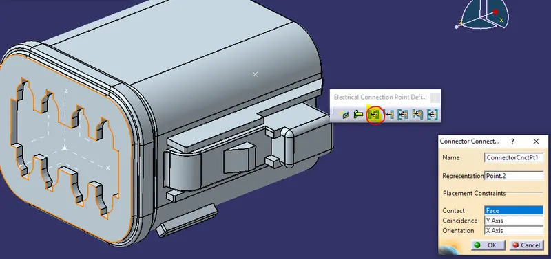
So like wise we need to define all the connector as electricaly.
Now Create the Electric wire harness context assembly and Geometric bundle as a subassembly containing all the electric parameters as shown below,
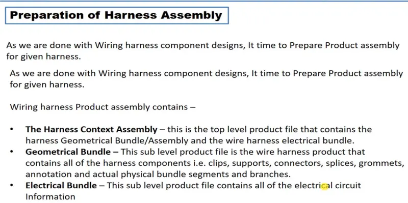
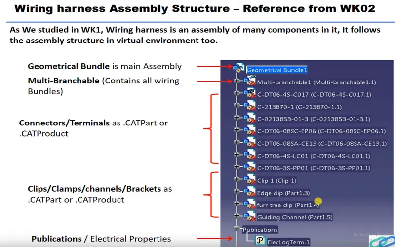
Add the all connectors which are electricaly defined to the Geomteric bundle assembly.
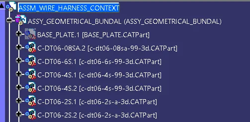
Then define this Geomteric bundle assembly as electricaly, for that we need to switch to Electric harness assembly workbench.

select Geometric Bundle then click on Geomteric bundle assembly (In specification Tree)
Now, to position all the connector as given in input file,
Create enviroment on which the bundle assembly will be placed.
Draw the sketch as given dimension in input just for referance purpose.
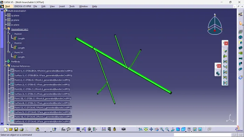
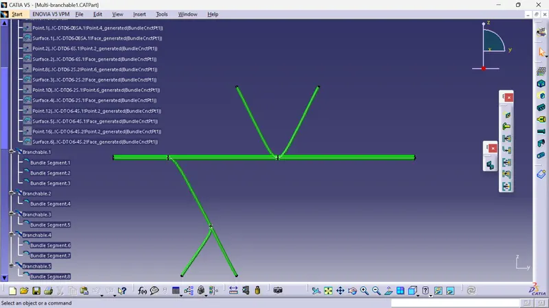
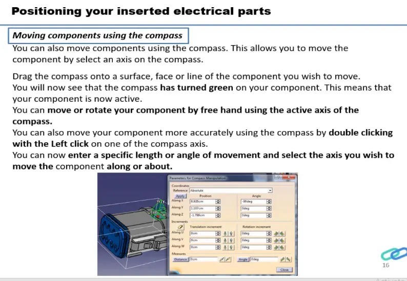
Switch to Mechanical assembly workbench, Position the connectors by using Manipulation, snap, smart move and compass commands.
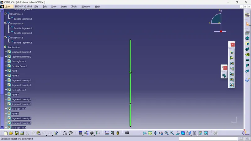
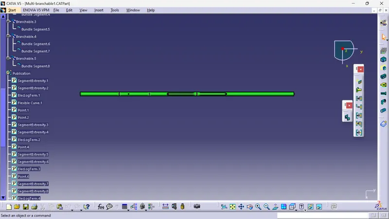
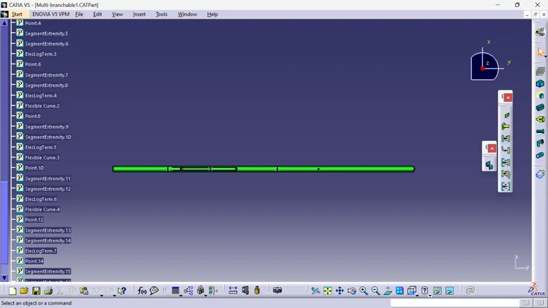
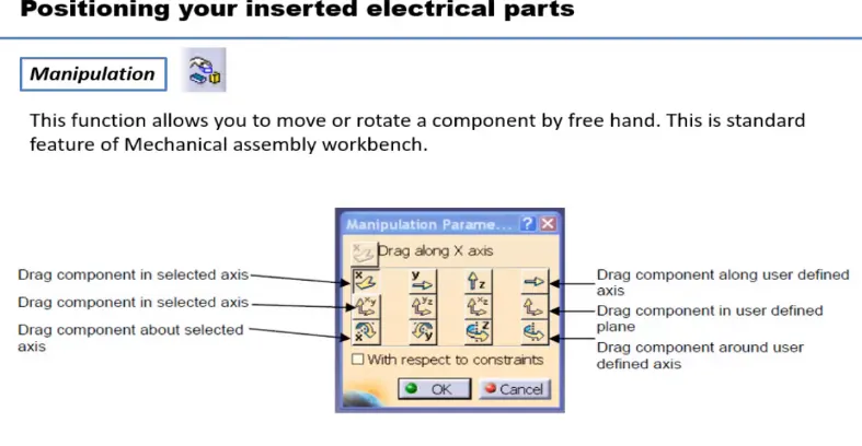
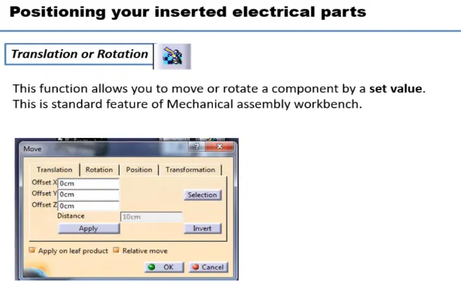
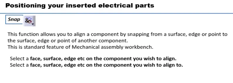
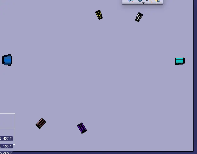
Now switch to Electric harness assembly workbench
select multi branchable documents
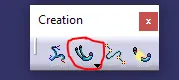
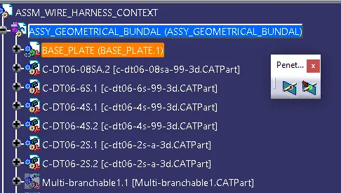
Now to route the harness, after selecting multi branchable documents workbech changed to wire harness installation.
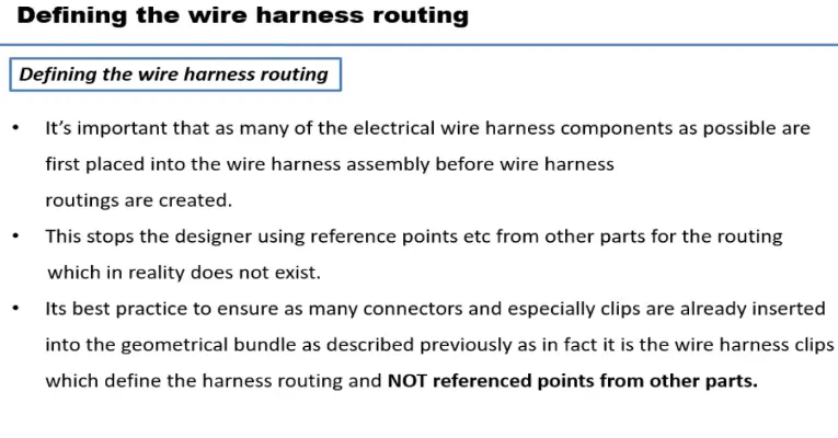
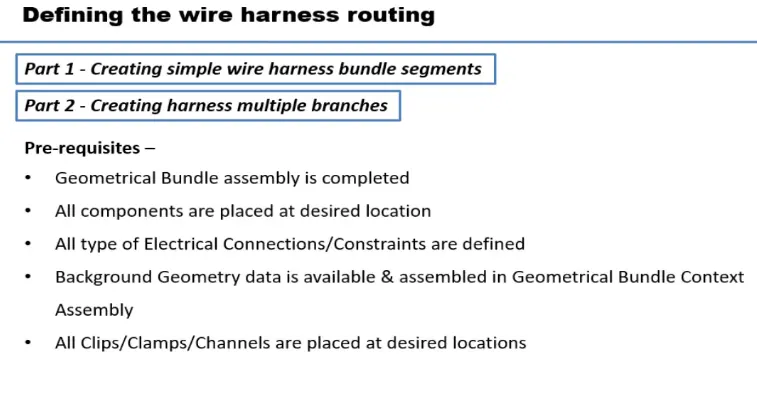
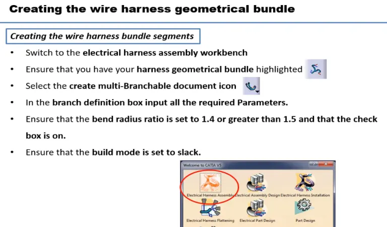
Click on Branch defination
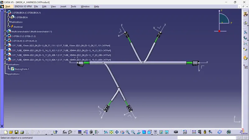
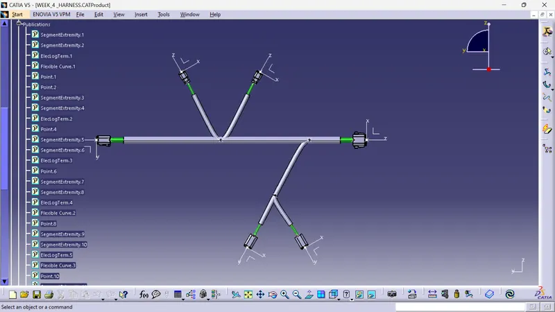
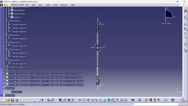
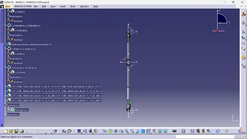
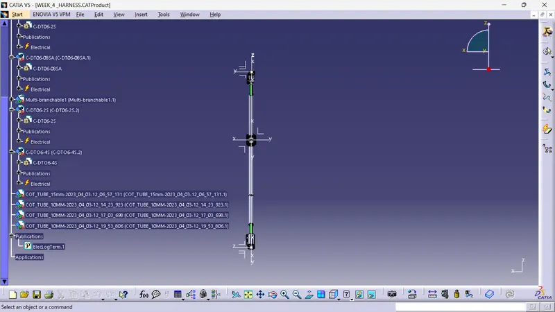
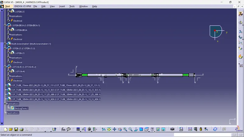
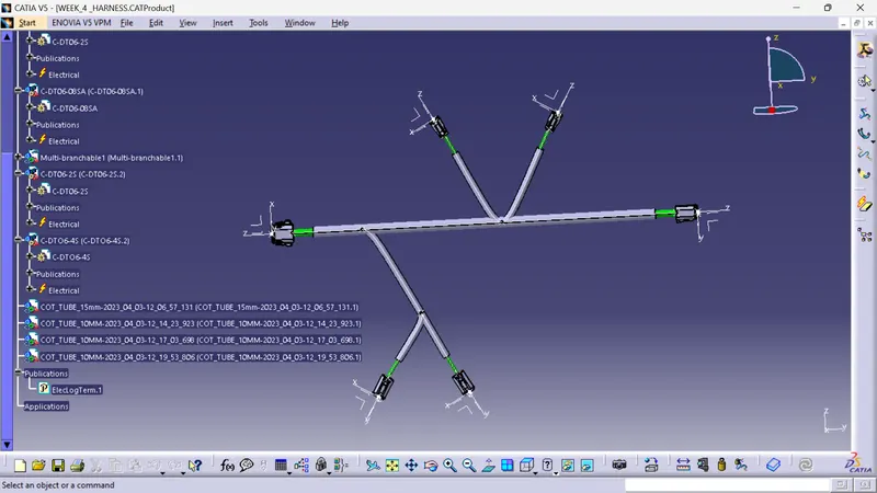
select the branch then give ratio or dimension for the point
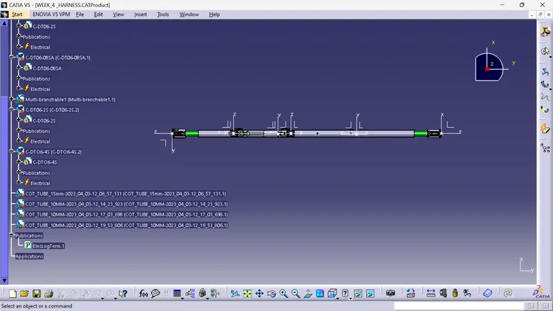
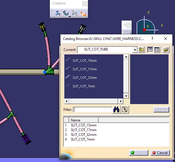
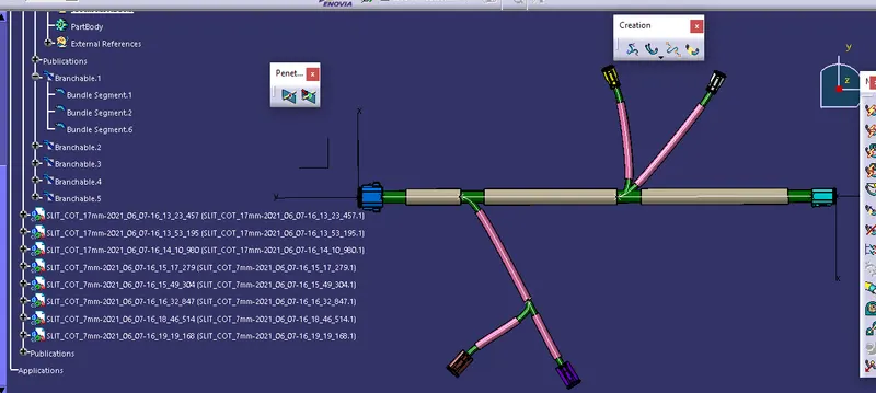
select protective covering then select branch - select catalog - select approprite slit cot tubes - give extrimity at start and end - ok
Conclusion:
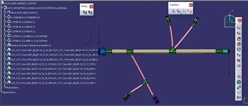
Thus, the Wiring Harness Layout has been designed with the given inputs and the protective coverings also added on the required branches(ref below image)