Hood design-Week 2
HOOD DESIGN
Introduction
Hood or bonnet is the hinged cover over the engine of the motor vehicles that is used to access the engine compartment. Hood assembly consist of different parts that combine to be used in a vehicle. Various parts of the hood are:
- Outer panel
- Inner panel
- Hinges
- Latch & Striker Mechanism
In this report we will discuss the various design consideration used for designing various parts of the hood inner panel
Master Sketch
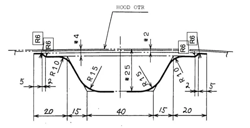
The master sketch utilised for designing the hood is shown below.
Embosses
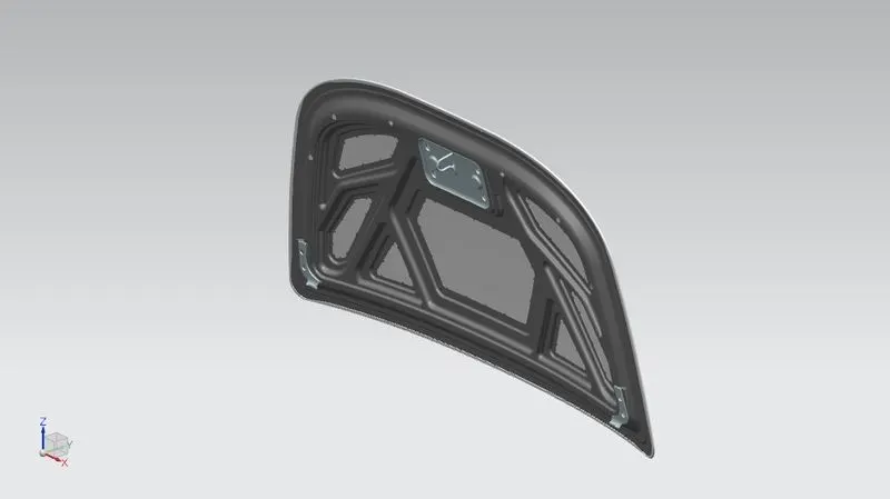
Various embosses were made in the hood inner panel by keeping in mind the following design considerations
- Pedestrian safety during the frontal crash.
- To improve the strength and stiffness of the body.
- the embosses were designed in such a way that the distance between the hood inner panel and the outer panel was kept 5 mm from the points it had to be attached to each other.
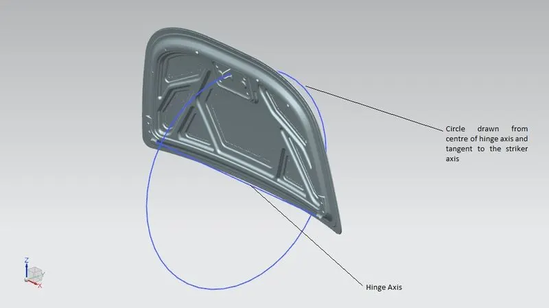
- Hinge emboss was done keeping in mind the striker and hinge axis correlation.
Mastic Data
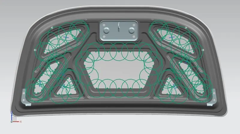
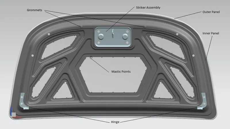
Mastic points are those points of the hood inner panel which are in contact with the hood outer panel with the help of sealants so as to minimise the effect of the vibrations produced by the engine.
Following are the design considerations for the mastic points
- Diameter of the mastic points was taken as 5mm.
- Distance between the mastic point and hood outer panel is 5mm.
- The distance between two mastic points was kept in such a way so as to minimise the vibrational effects.
Hemming
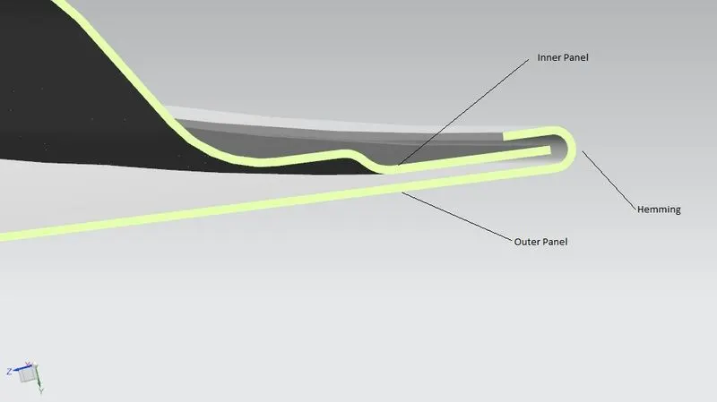
Hemming is the process of joining the hood inner panel and the hood outer panel. Due to the styling finish of the vehicle both the panels cannot be joined using the welded joints so in order to avoid these joints hemming is used. Hemming for the hood was done with the help of the hemming data as shown.
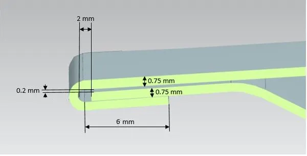
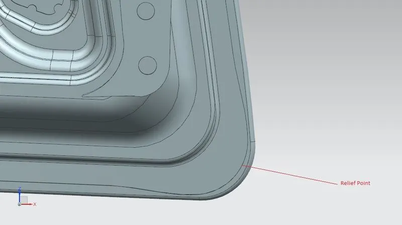
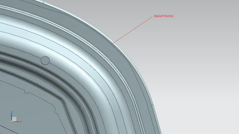
In the corners a relief is to be provided during hemming and for this relief following data was used.
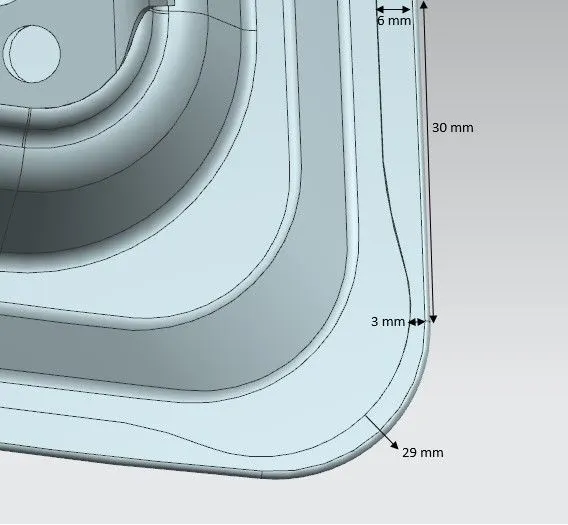
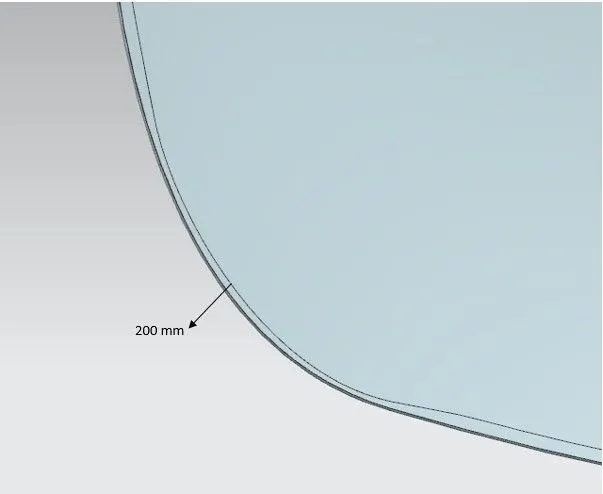
The figures below show the hemming and relief points in the designed model.
Assembly
PRESENTATION:
OBJECTIVE
- Design Outer Panel with the Hem
- Develop the Inner Panel
- Develop all the Necessary Reinforcements
- Mirror and position the Hinge & Striker
- Provide Mastic Data
- Provide the required Emboss definition
HOOD ASSEMBLY
A car hood is the metal part that covers the engine of an automobile.Hood Assembly consists of Hood inner Panel, Hood Outer panel, Reinforcement panels, Striker, Hinge,Mastics and Wiping system. Below is the pic of Hood Assembly designed.
HOOD INNER
Hood Inner panel is the main structure of the hood assembly. This part adds stiffness to the Vehicle to with stand the frontal crash and has provision to hold hinge, Stopper and striker. It has embossing to add more stiffness to the part and cutout to reduce the overall weight. It has mastics to be fixed to the Hood Outer panel.
HOOD INNER EMBOSSING
Embossing is done to add more stiffness to the panel. Adding embossing will add more strength and stiffness to the part. The embossing value must be optimum to ensure all the part requirement such as manufacturing feasiblity, Frontal crash requirements and Pedestrian crash requirements.
- 40mm Hollow body given near Striker and stopper region for more crushable zone above hard part for pedestrian performance.
- 8mm clearance with Hood outer for Mastic zone.
HOOD OUTER HEMMING
Hemming is an Operation used to fixed two panels together. Hood Outer is fixed to Hood inner by hemming Operation.
Hemming Operation is not done at hood corners to avoid wrinkling of sheet metal.
Hood Striker
Hood striker is the part which is used to fix the Hood assembly with the latch. The Hood striker must be positioned in such a way so that the striker is perpendicular to path of Hood trajectory.
Since this zone is load bearing area additional reinforcement is provided to have more stiffness.
Section Analysis
Section Analysis is done to understand the Load bearing capacity of the panel before CAE analysis. MOI is measured along the principle axis to understand the characteristics of the panel.
- Max MOI 4.9 * 10^4 mm4 about Y axis (More stiffness for Frontal crash)
- Min MOI 1.8 * 10^4 mm4 about X axis (Less stiffness for Pedestrian crash)
Draft Analysis
Draft analysis done to find the undercuts in a panel. This the most important study for manufacturing feasibility of the panel. Here the green zone represents the draft angle is more than 7 degree.
- Check for Draw direction as vertical to vehicle
- Draft angle 7deg
Conclusion
Thus Hood design is completed with all the necessary design considerations.