Week 10- Assembly Workbench
ASSEMBLY WORKBENCH
Aim: To create the part models and assembly of the components from the given 2d-drawings and then to create drafting.
Introduction:
Assembly modeling:
Assembly modeling is a process of creating design that consists of two or more components assembled together at their respective work positions. The components are brought together and assembled in Assembly Design workbench by applying suitable parametric assembly constraints to them. The assembly constraints allow the designer to restrict the degrees of freedom of components on their respective work positions. The assembly files in CATIA are called Product Files.
Types of Assembly Design Approach:
In CATIA we can create assembly models by adopting two types of approaches.
- Bottom-up Assembly
- Top-down Assembly
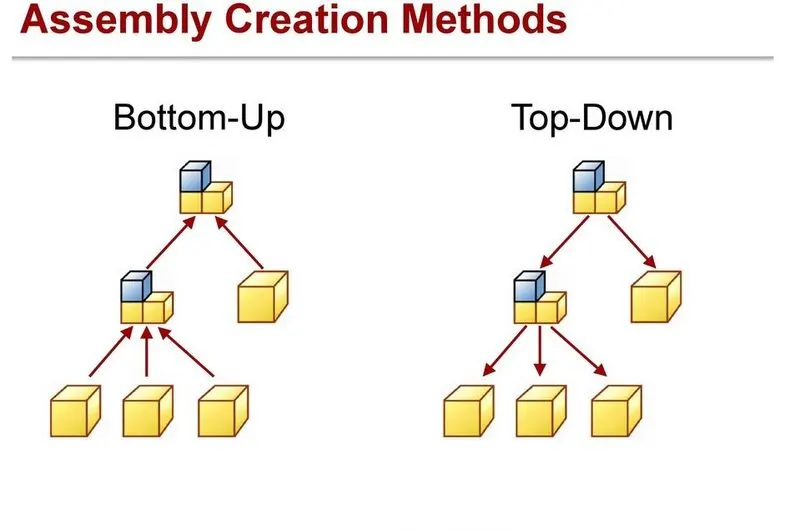
1.Bottom-up Assembly:
The bottom-up assembly is the most preferred approach for creating assembly models. In this approach, the components are created in Part Design workbench as (*.CATPart) file. Then the product (*.CATProduct) file is started and all the previously created components are inserted and placed in it using the tools provided in the Assembly Design workbench. After inserting each component, constraints are applied to position them properly in the 3D space with respect to other components.
2.Top-down Assembly:
In the top-down assembly design approach, components are created inside the Assembly Design workbench. Therefore, there is no need to create separate part files of the components. This design approach is completely different from the bottom-up design approach. Here, we have to start the product files first and then one by one create all the components. Note that even though the components are created inside the product file, they are saves as individual part files and can be opened separately later.
Quick Return Mechanism:
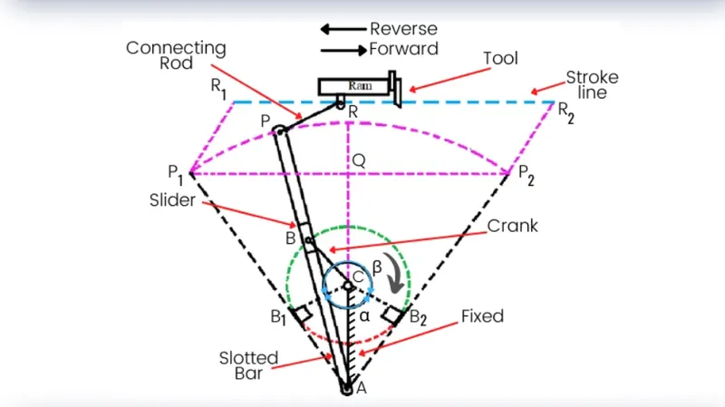
The quick return mechanism is the inversion of a single slider crank chain. The main purpose of this mechanism is to convert the rotary motion of the crank into the reciprocating motion of the ram. It consists of crank, slider and slotted bar, connecting rod and ram. This mechanism has a different velocity of ram in the forward stroke and in reversed stroke. The movement of reverse stroke is faster than the forward stroke. The mechanism is generally used in the applications where the velocity of the tool at return stroke is not considerable for example, shaper machine, slotter machine etc. Therefore, the faster stroke of the ram, during reverse stroke helps to reduce the total machining time.
Constant Velocity Joint:
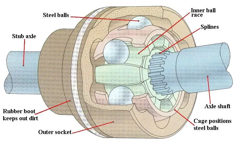
CV or Constant velocity joints are an essential component of front-wheel-drive cars. They are built into the front axle of cars and, on occasion, can be found on rear axles as well. They join the main drive axle to the shaft attached to the front wheels. Their purpose is to efficiently and continuously transfer power from the one side of the shaft to the other, at a range of angles. They are near the front wheels and are protected by black bulbous rubber boots filled with MoS2 grease.
Design of Quick Return Mechanism:
Procedure:
Sketch creation:
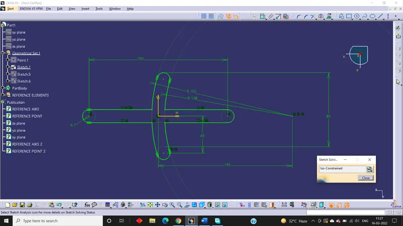
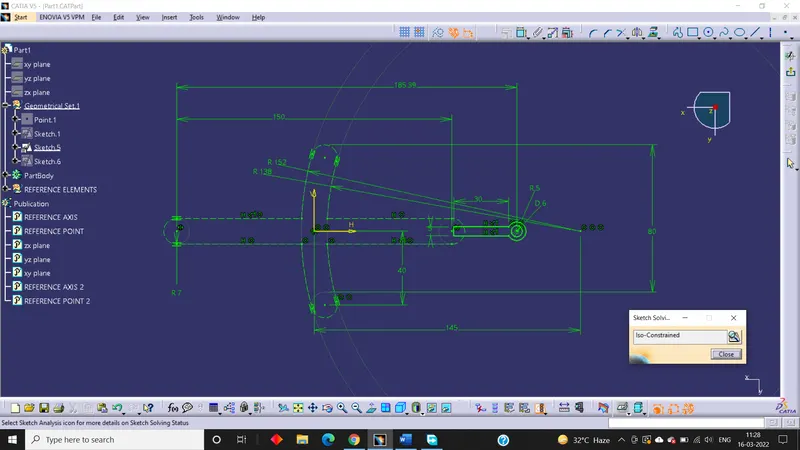
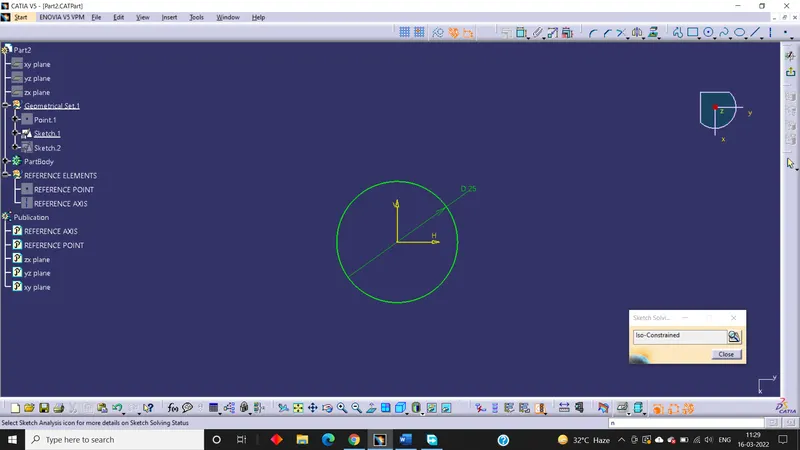
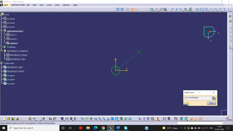
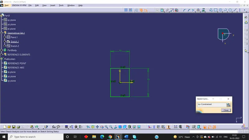
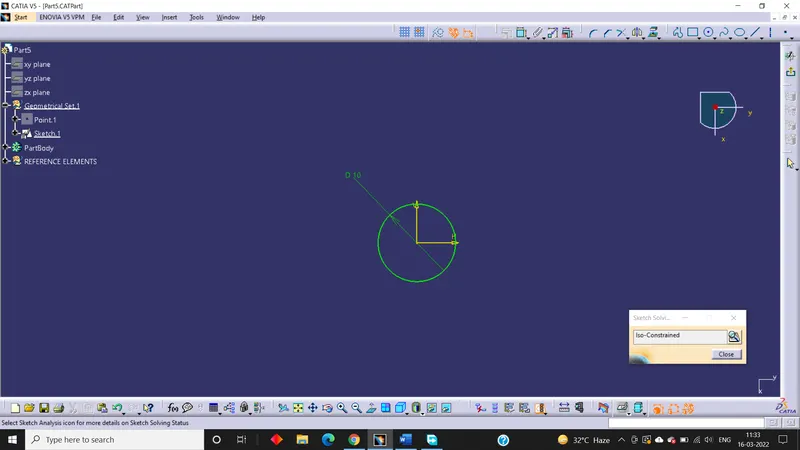
First of all, sketches are created from the drawings provided as input.
Part 1 sketch:
Part 2 sketch:
Part 3 sketch:
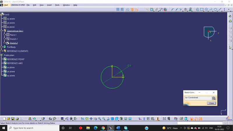
Part 4 sketch:
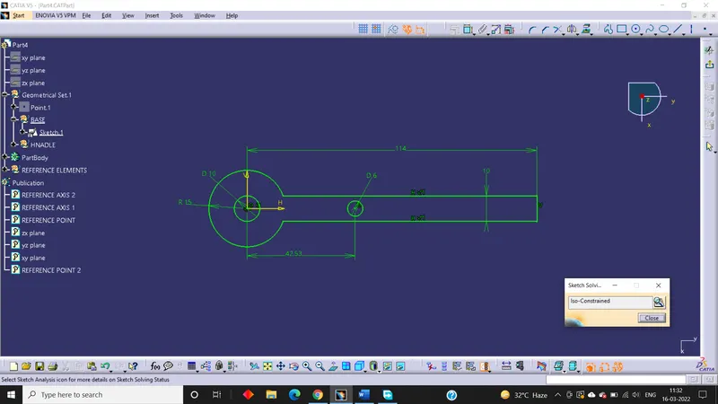
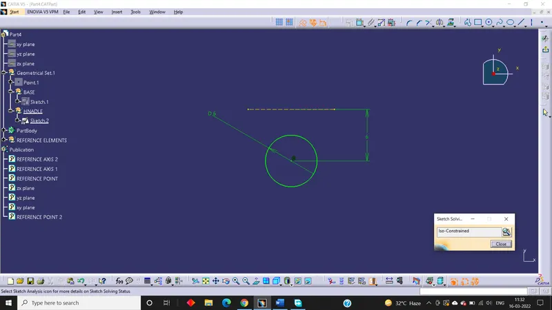
Part 5 sketch:
Part creation:
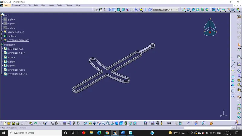
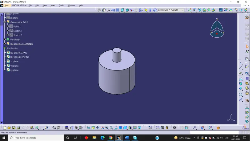
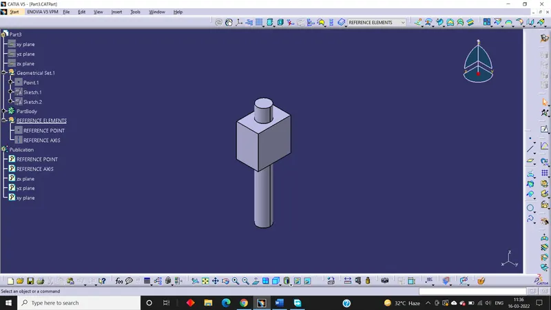
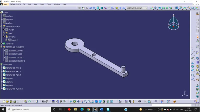
From the sketches created earlier, the individual parts are created using Boolean operation.
Part 1:
Part 2:
Part 3:
Part 4:
Part 5:
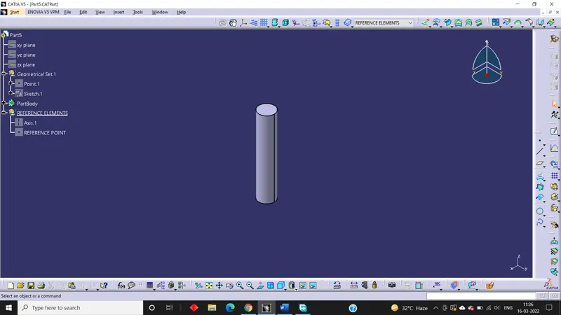
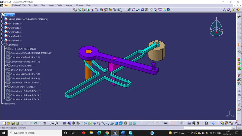
Assembly creation:
- First of all, we have to create a new .CATProduct and insert all .CATPart by using existing component command.
- Then a reference elements for each parts should be created.
- After that reference elements like axis, points etc. should be added wherever needed.
- Then a parent reference should be created and fixed constraints is added to it.
- Now using constraints tool all the parts should be assembled to the parent reference and to one another.
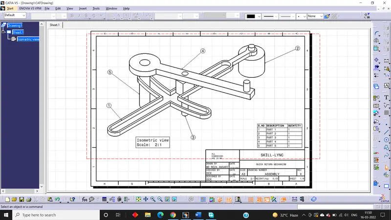
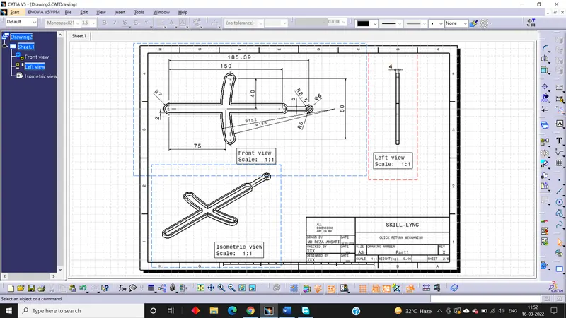
Drafting:
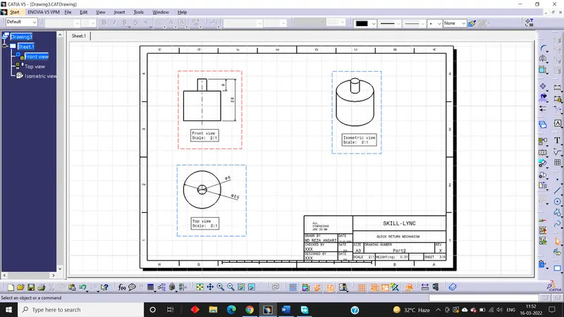
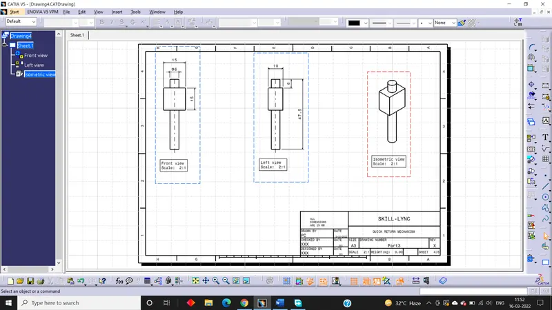
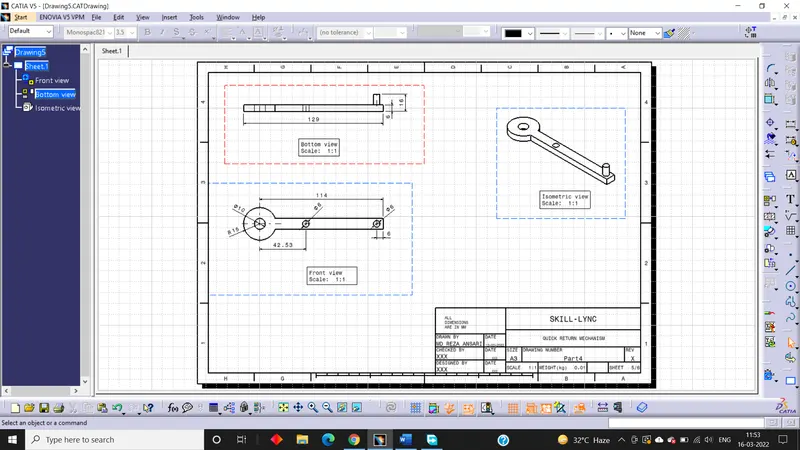
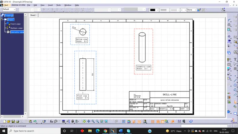
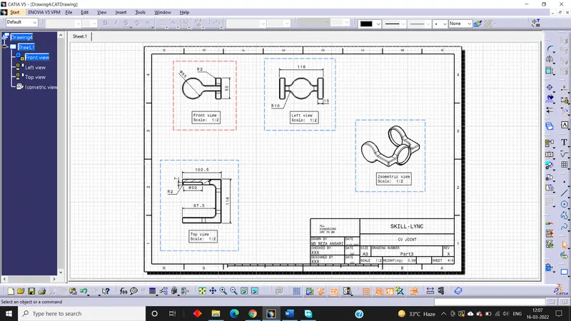
Making the use of the drafting tools we have to create a 2D drawing.
Design of CV Joint:
Procedure:
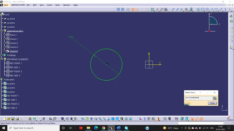
Sketch creation:
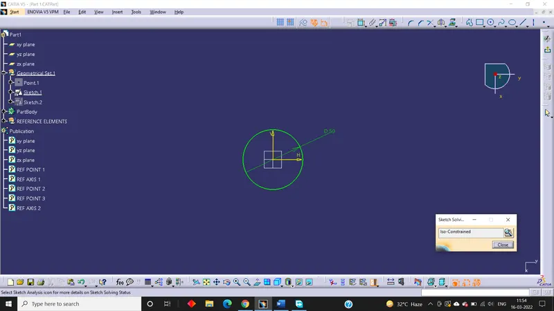
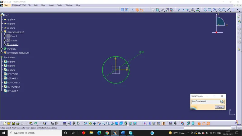
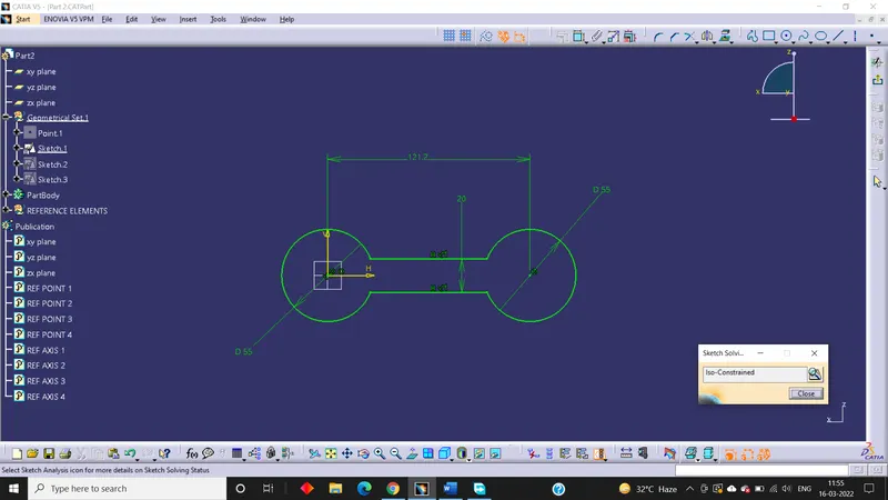
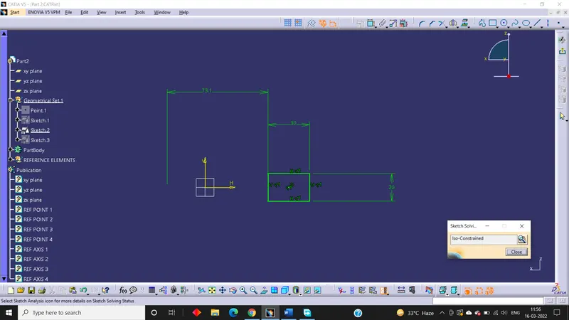
First of all, sketches are created from the drawings provided as input.
Part 1 sketch:
Part 2 sketch:
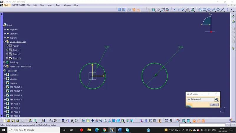
Part 3 sketch:
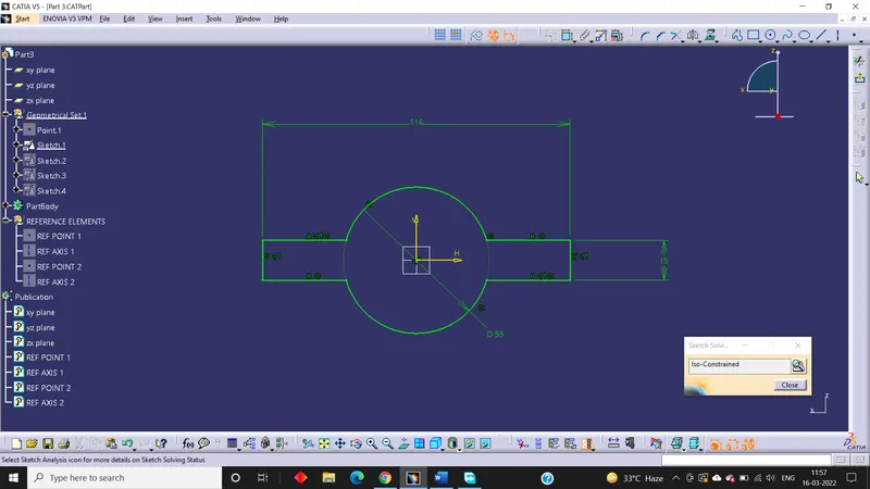
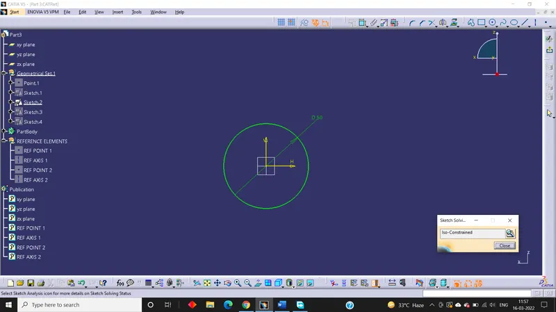
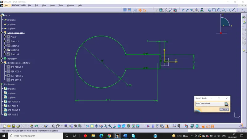
Part creation:
From the sketches created earlier, the individual parts are created using Boolean operation.
Part 1:
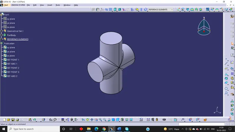
Part 2:
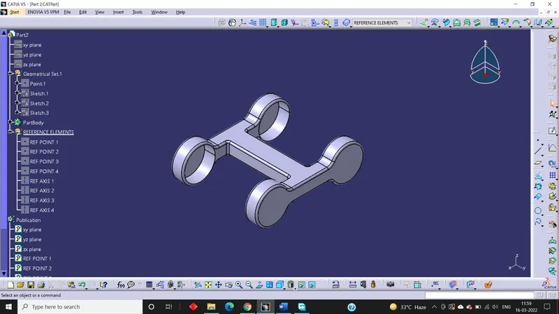
Part 3:
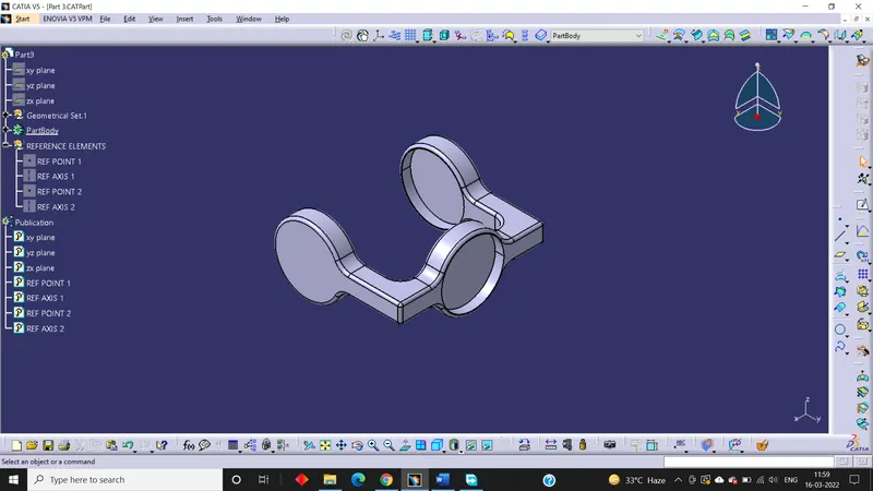
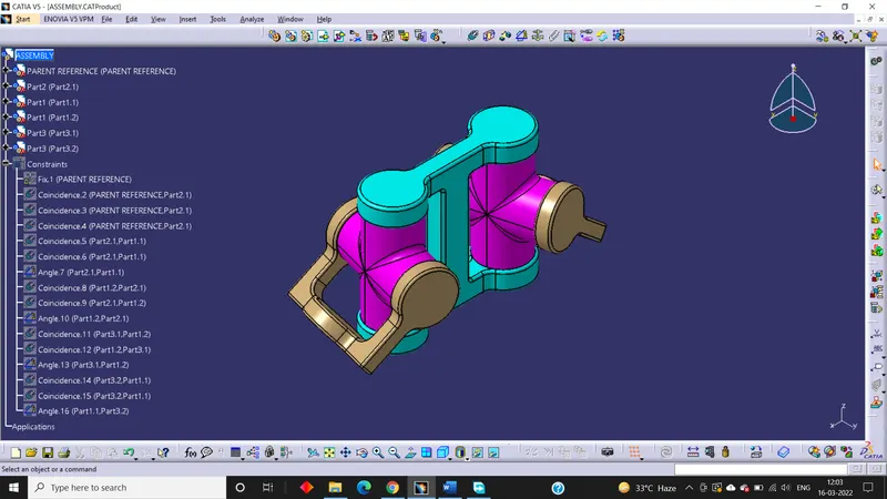
Assembly creation:
- First of all, we have to create a new .CATProduct and insert all .CATPart by using existing component command.
- Then a reference elements for each parts should be created.
- After that reference elements like axis, points etc. should be added wherever needed.
- Then a parent reference should be created and fixed constraints is added to it.
- Now using constraints tool all the parts should be assembled to the parent reference and to one another.
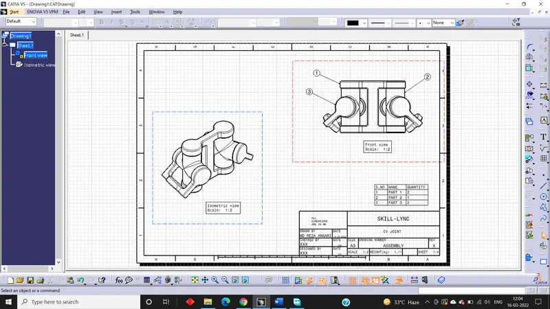
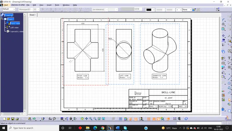
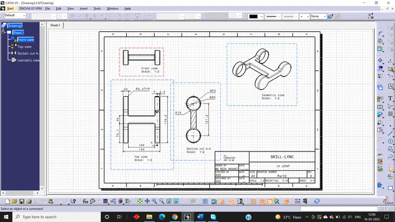
Drafting:
Making the use of the drafting tools we have to create a 2D drawing.
Conclusion:
All the parts of CV joint and Quick Return Mechanism were created, assembled and then drafted.