Week 1- Mixing Tee
AIM :- To compare the mixing effectiveness in short and long T section of pipe or duct when hot inlet temperature is 360C & the Cold inlet is at 190C. and also use the k-epsilon and k-omega SST model for this study.
Objective :-
- we have to study these both cases
Case 1
- Short mixing tee with a hot inlet velocity of 3m/s.
- Momentum ratio of 2, 4.
Case 2
- Long mixing tee with a hot inlet velocity of 3m/s.
- Momentum ratio of 2, 4.
- In a table, compare the following values from the 2 cases.
- Cell count
- Average outlet temperature
- Number of iterations for convergence
- Velocity and temperature contour plots and also line plots on the cut planes along and across the pipe.
- Perform Mesh independent study for any one case and Discuss the effect on length and momentum ratio on results.
About the project:-
Mixing tee:-
In the mixing process primarly Determine by the inlet velocity jet because here the main we are consider the momentum ratio of the jets.Mixing tees are widely used in the petrochemical industry, in which two fluid streams with different physical and/or chemical properties mix together. When there is a large temperature difference between the two streams, large metal temperature fluctuations can occur in the region where the two streams meet if proper design steps are not taken. The temperature fluctuations in the metal may lead to thermal fatigue of the pressure boundary piping. If through-wall cracking occurs, the fluid may leak, possibly causing a fire and damage. It is therefore imperative to make sure that the temperature fluctuations are such that the piping system can withstand them. Options can include improving the mixing of the two streams to reduce the temperature fluctuations through redesign of the piping system such that the momentum ratio of the two fluid streams is favorable to rapid mixing, or to install devices that protect the pressure boundary piping, e.g., injection quills or thermal sleeves in the region where the temperature fluctuations are higher than a thermal fatigue threshold. This region includes the T-junction and a length of several to many main pipe diameters downstream from the T-junction.
Computational fluid dynamics (CFD) modeling, such as wall-resolved large eddy simulation (LES), can provide accurate predictions of the mixing behavior, including velocity, concentration and temperature fields, in a mixing tee. The variations of the transient fluid temperature can therefore be used to identify a location in the main pipeline, after which the maximum temperature difference is less than a given value.
In this Project we are going to use the ANSYS FLUENT Software to see the mixing effectivness of two fluids at T- section pipe and these fluids are coming from the different inlets at different temperatures and velocities. The hot inlet Temperature we are going to use is 360C & the Cold inlet is at 190C and for the different velocities we are going to use momentum ratio.
Momentum ratio = Momentum ratio = velocity at cold inlet / velocity at hot inlet
Step1: Geometry (pre-processing)
After selecting the Geometry startclaim is going to start It is a software to create CAD designs for CFD and FEA.
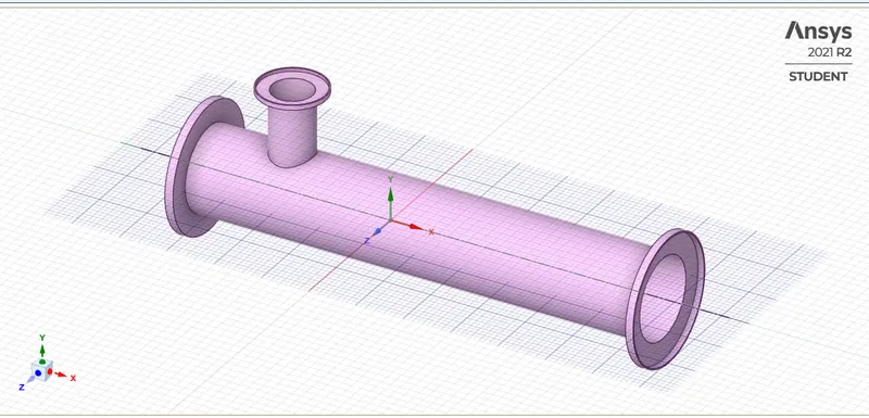
After that we have to extract the fluid area where the fluid flows go to prepare and select the Volume Extract by selecting the edges of the geometry and Then hide and supress for Physics the solid model, It means it is not going to loaded when we are doing the simulation process.
Step2 : Mesh
When the Mesh Software has started first we have to create the names of the geometry by Named selection command Select by edges name given in this project are inlet x, inlet y, outlet and walls. After this we are generating mesh and the default mesh size is around mm and we are check the mesh quality
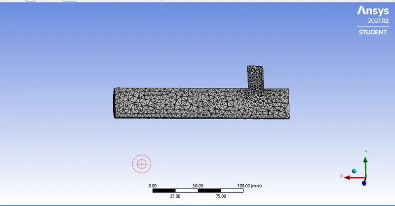
Step3 : Setup and Solutions
Start the setup launching the Fluent In this you have to check the mesh updated or not After opening the fluent First we have to setup for physics - In this case we are solving for steady state for small mach number- pressure based solver. Velocity formulations is absolute and for Temperature energy equation we are using.
For Turbulence model in the viscous section you can use the K- Epsilon and K-omega models as per the equations. Now, we are going to add the boundaries values like Velocity and Temperature for the geometry like inlet velocity and inlet Temperature etc.
After that In the case we are going to calculate the average temperature at Outlet and standerd deviation for mixing effectiveness of the two fluids at T section by the solution you can get the reports and then initilase the initial conditions and after that hit the calculation we got these reports mentioned below.
Case1: Short mixing tee
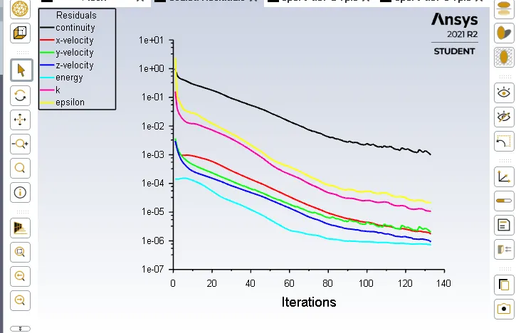
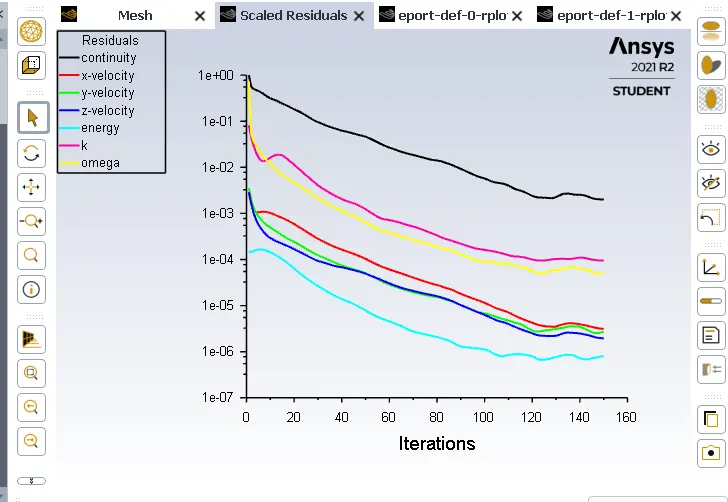
a) For both the models k- Epsilon and k-omega and momentum ratio is 2 where the hot inlet velocity is 3 m/s and cold inlet velocity 6 m/s
Residual graphs- to check the solution how much numerically accurate
Epsilon model k-Omega model
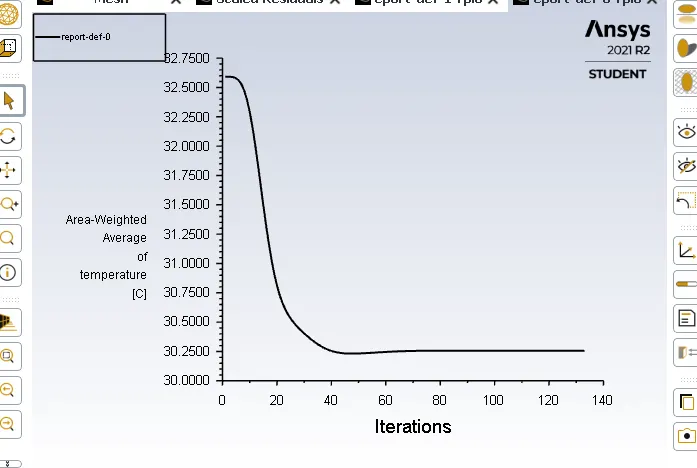
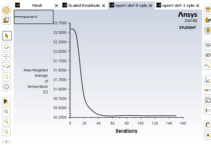
Area - weighted graphs Average of Temperature- we use this plot to get the outlet temperature
Epsilon model k- Omega model
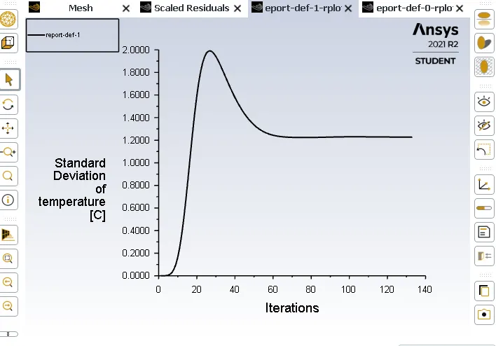
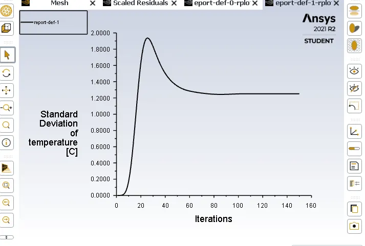
Standered Deviation graphs- To understand the effectiveness of mixing
Epsilon model k- Omega model
Conclusion:-
- In these plots we can clearly see the there is minimum difference between them but In the residual graph you can clearly see the k Epsilon model after some value the solution coverges and the plot becomes uniform.
- The residual plot always shows downward slope or decreasing line means the lower the residual value is the more numerically accurate the solution.
- K -Epsilon model predicts well far from the boundaries or walls and k - omega model predicts well near walls. Even though it depends on Y+. we alose use SST model which is a combination of these
- K- epsilon model shows standerd results because it becomes uniform after certain value So, in this case we are going to use Kepsilon model.
Step4 : Post processing (results)
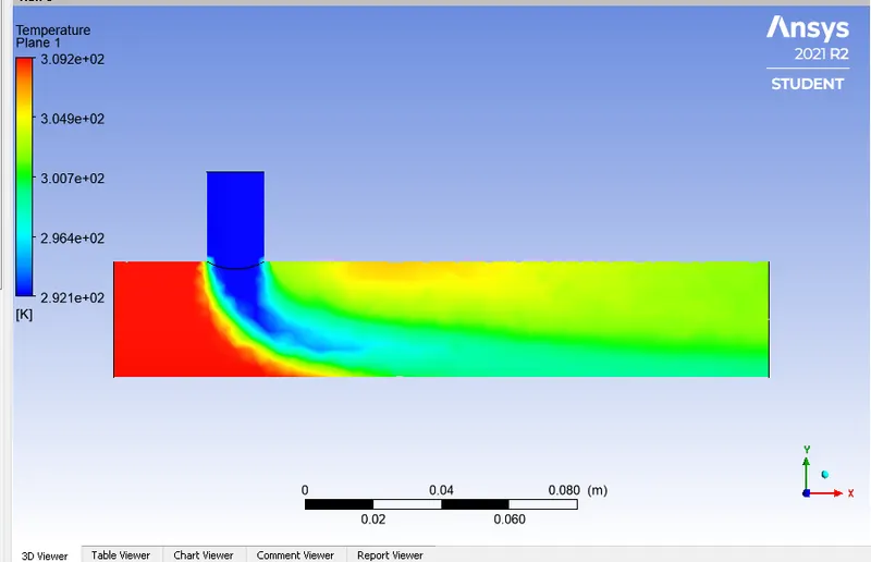
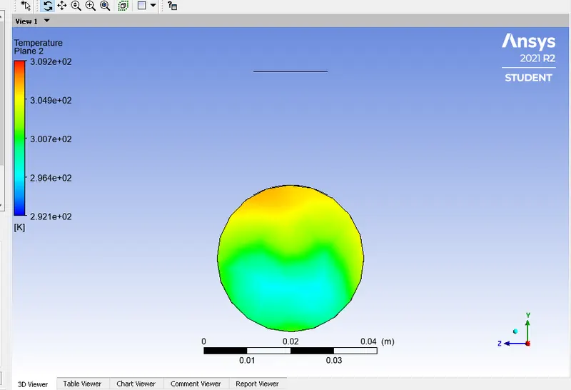
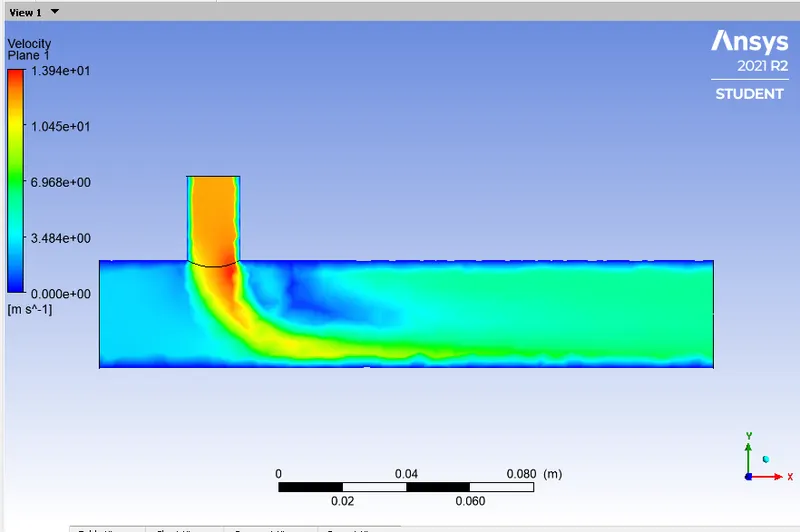
Velocity and Temperature along and across the pipe contour plots :- For both the models there is no such difference in the Temperature and Velocity profile So, we are showing you only omega model distributions for velocity and Temperature for momentum ratio = 2
Along the pipe
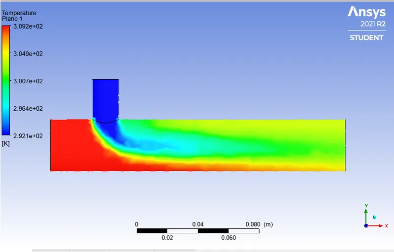
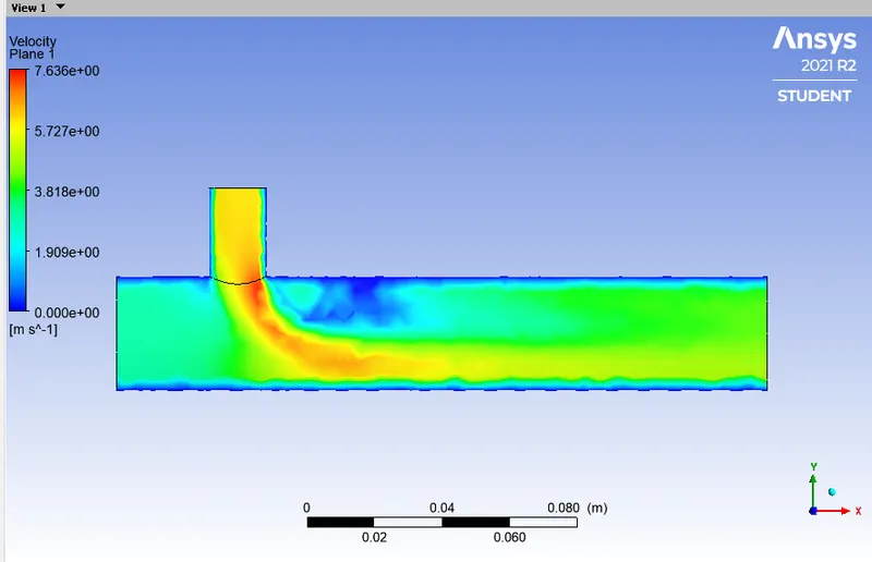
In these plots we got diffusive looking profile along the mixing area It is due to large mesh cells called coarseb simulation.
Across the pipe
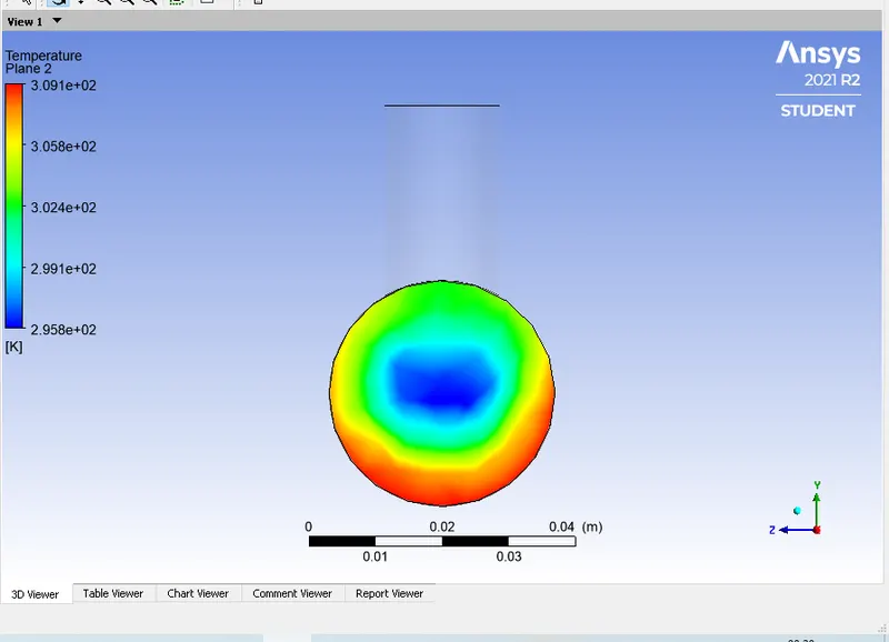
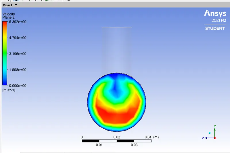
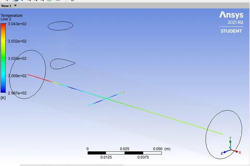
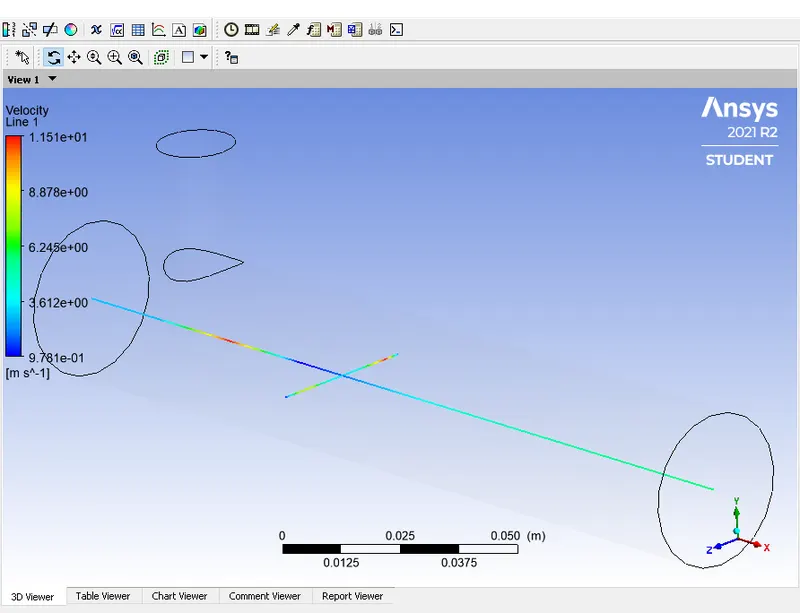
Velocity and Temperature along and across the pipe line plots :-
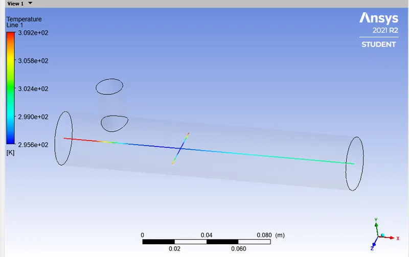
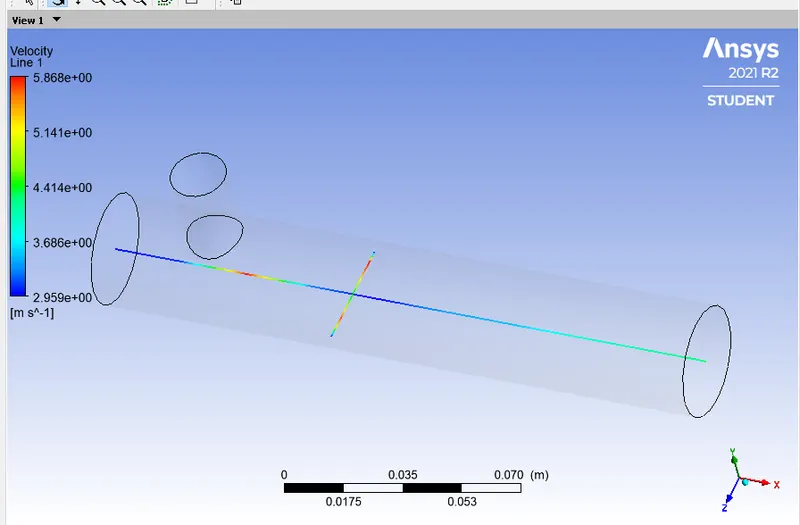
b) k- Epsilon model momentum ratio is 4 where the hot inlet velocity is 3 m/s and cold inlet velocity 12 m/s
Residual graph
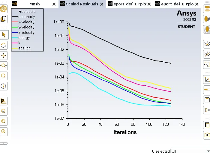
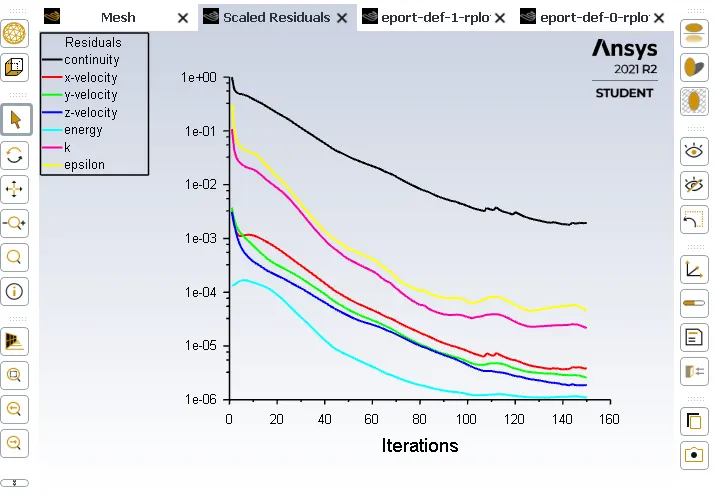
The residual plot of momentum ratio =4 are more inform means there is no significant diffrence errors to got the converged solution as compared the momentum ratio 2 the value is still 1e-6
Area - weighted graph Average of Temperature
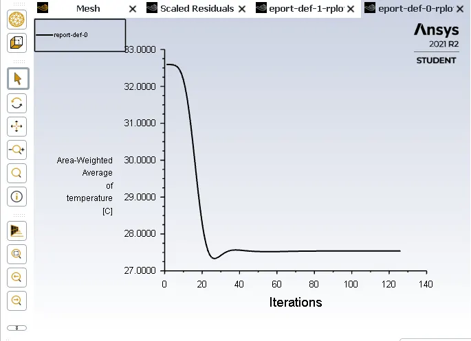
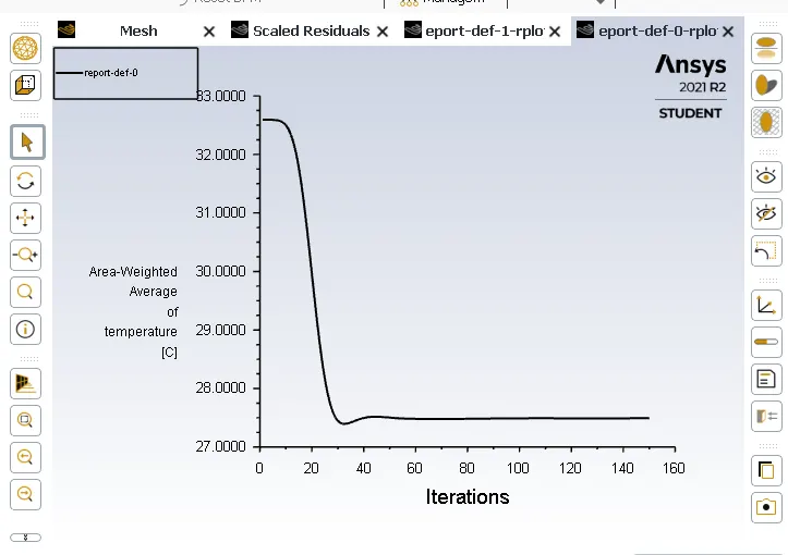
In the section where the inlet hot or inlet cold fuilds mixes the temperature is get high for some seconds and after that we got uniform average outlet temperture.
Standered Deviation graph
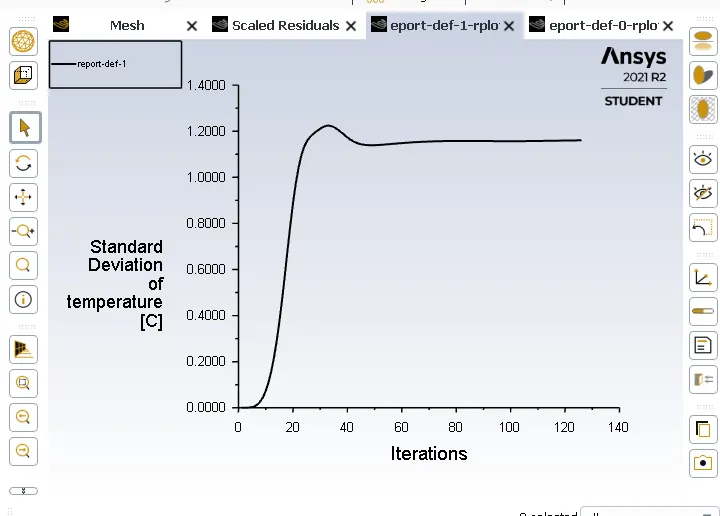
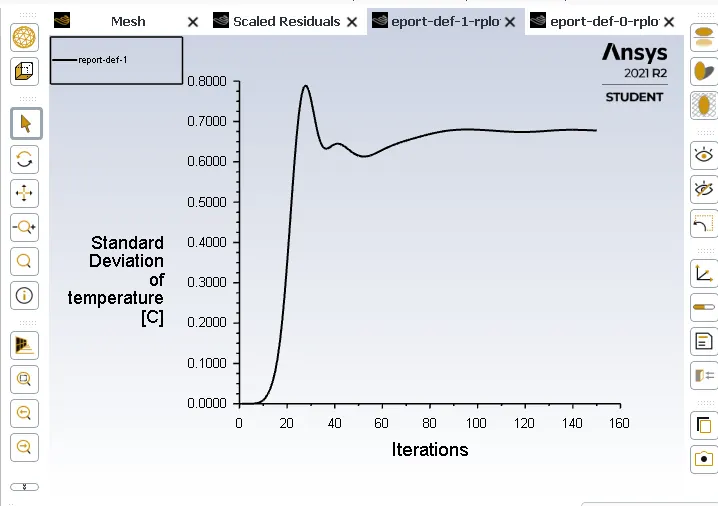
In these graphs we can clearly see that After increasing the velocity its not seem steady or uniform as compared the momentum ratio 2 as standered deviation is low we got the uniform temperature.
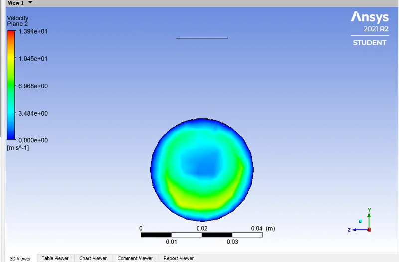
Velocity and Temperature along and across the pipe contour plots
Temperature distribution
Velocity distribution
Velocity and Temperature along and across the pipe line plots :-
Temperature distribution
Velocity distribution
C) Mesh Independent study for any one case:-
In the CFD we have to solve the Governing equations of Fluid dynamics for each cells So, the more cells the more equations we have to solve and that's why it takes time in simulations as per increment in the cell counts.The more the mesh size the cell count number is less and when you decrease the mesh size the cell count is more So, each and every increment of mesh cells you get converged solution means your standerd deviation of outlet temperature should reach to steady value as you progressively refining the mesh.
It occurs at a particular tolerance and when it is happens your solution is said to be grid converged.
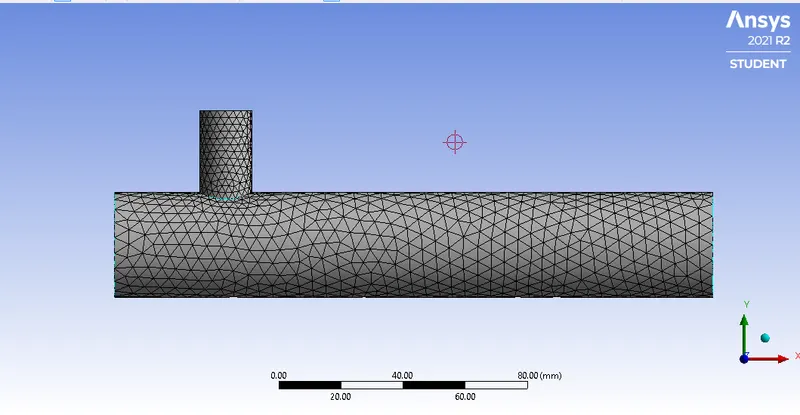
We are going to do Mesh Independent Test for momentum ratio = 2 K-Epsilon Turbulence Model
Mesh Generation
Element size = around 10mm default Element size = 5mm
Element size = 2.5mm
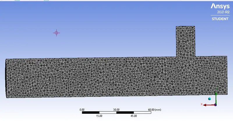
We can easily conclude that these pictures how the mesh size increses and the number of cell counts in the geometry will increses. When we increase the number of cells the simulation time increses Quadratically way as well. As you add more number of cells your solver take more iterations to converge a particular value whereas, If the mesh is coarse (means few cells) the linear solver converges very fast.
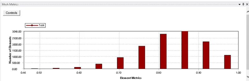
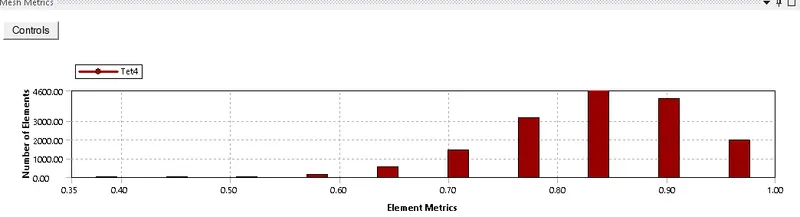
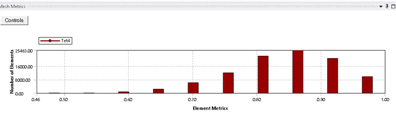
Mesh quality for 3 cases
Element size = 10mm
Element size = 5mm
Element size = 2.5mm
Residual graphs for all 3 cases to compare the results
Element size 10mm
Element size = 5 mm
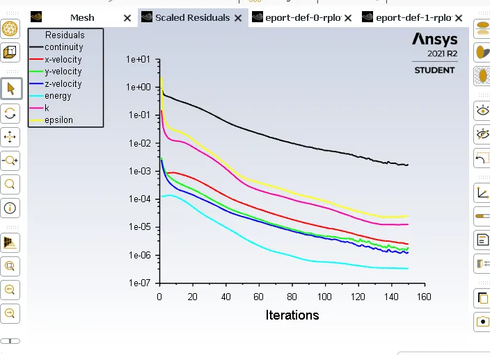
Element size = 2.5mm
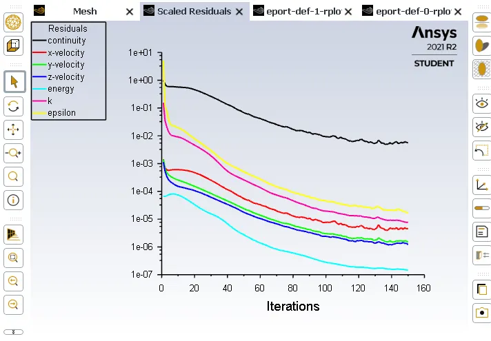
AS you see the Resdiual graph slope decreases rapidly means the value of residuals increases to 1e-6 to 1e-7 means there is numerically inaccurate because the lower the residual values the numerically we got accurate results.AS you also see the number of iterations will increase to get the converge solution.
Area - weighted graph Average of Temperature
Element size 10mm
Element size = 5 mm
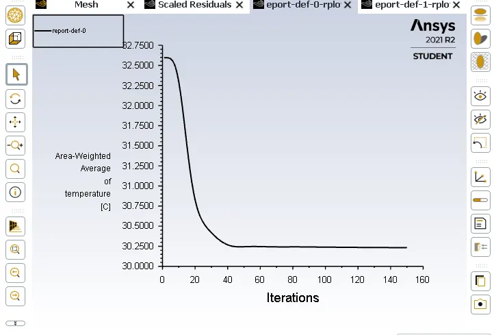
Element size = 2.5mm
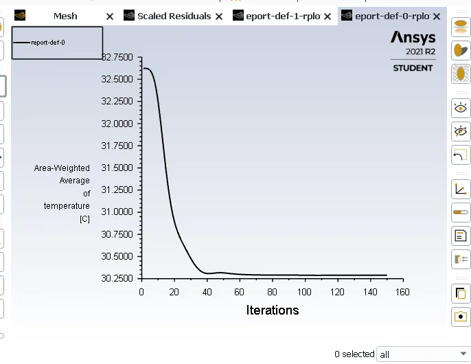
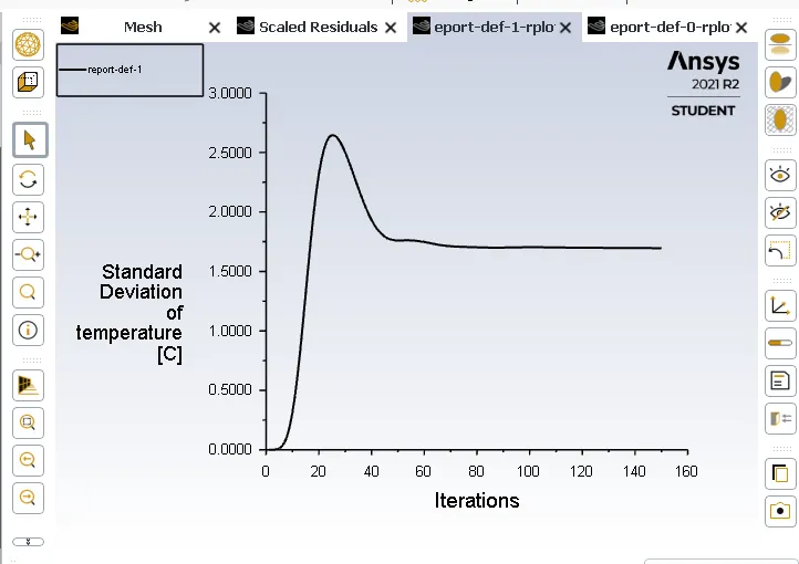
Standered Deviation graph
Element size 10mm
Element size = 5mm
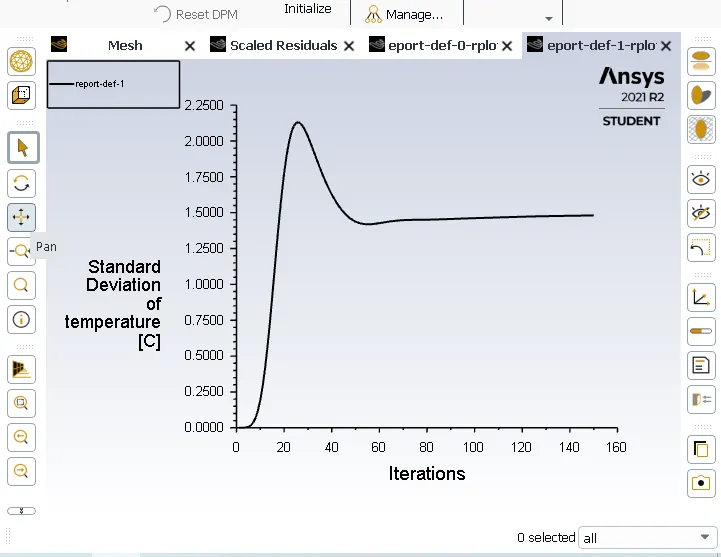
Element size = 2.5mm
Velocity and Temperature along the pipe contour plots for 3 mesh sizes
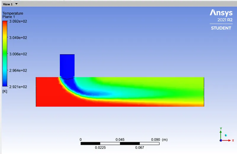
Temperature Distribution contour plots
Element size = 10mm Element size = 5mm
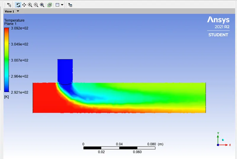
Element size = 2.5mm
Velocity Distribution contour plots
Element size = 10mm Element size = 5mm
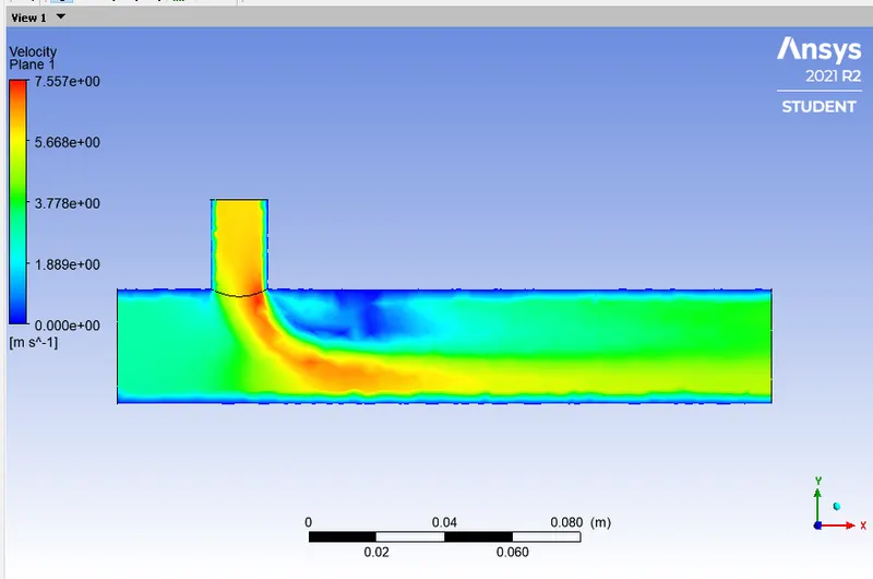
Element size = 2.5mm
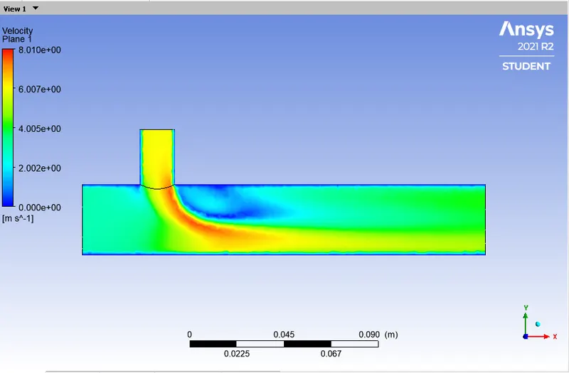
Table for comparing the following values from this cases
| Element size (in mm) | Cell count | Average outlet temperature | Number of Iterations | Error(%) |
| around 10 mm | 12403 | 30.15 | 135 around | |
| 5 mm | 15908 | 30.20 | 145 around | 0.16 |
| 2.5 mm | 98517 | 30.25 | 146 around | 0.17 |
Case 2 Long mixing tee
a) For the model k- Epsilon and momentum ratio is 2 where the hot inlet velocity is 3 m/s and cold inlet velocity 6 m/s
Residual graph Area weighted average of temperature graph
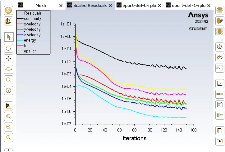
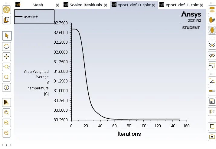
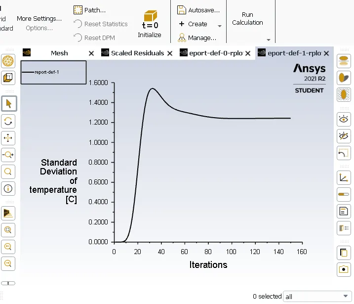
Standered deviation graph
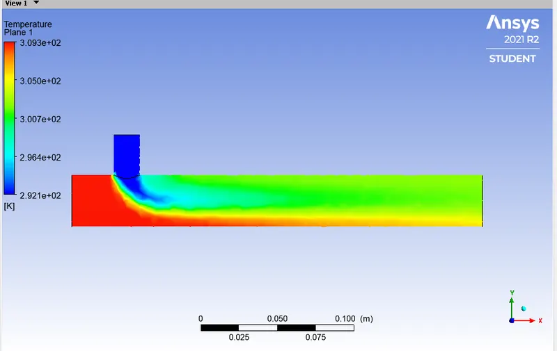
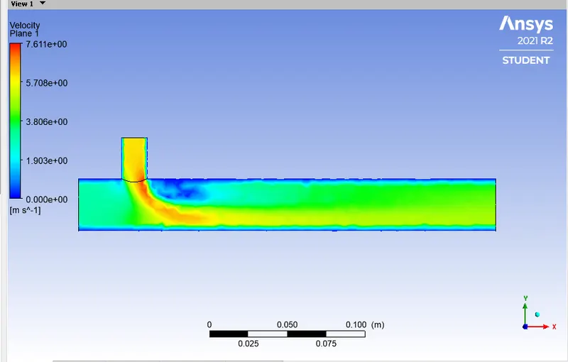
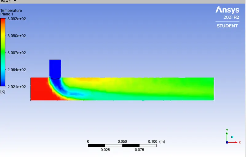
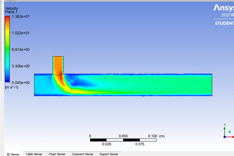
Velocity and Temperature along the pipe contour plots
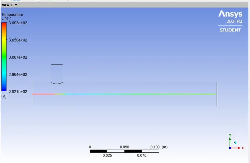
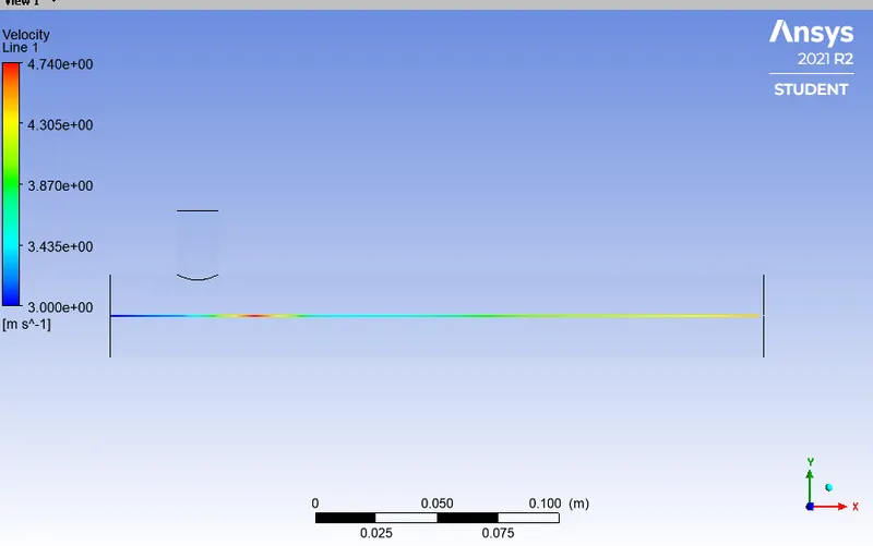
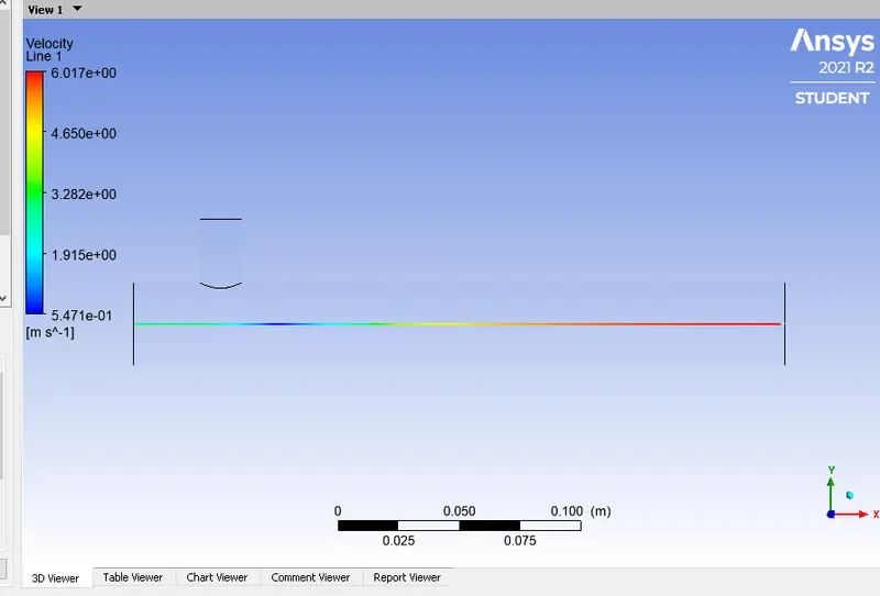
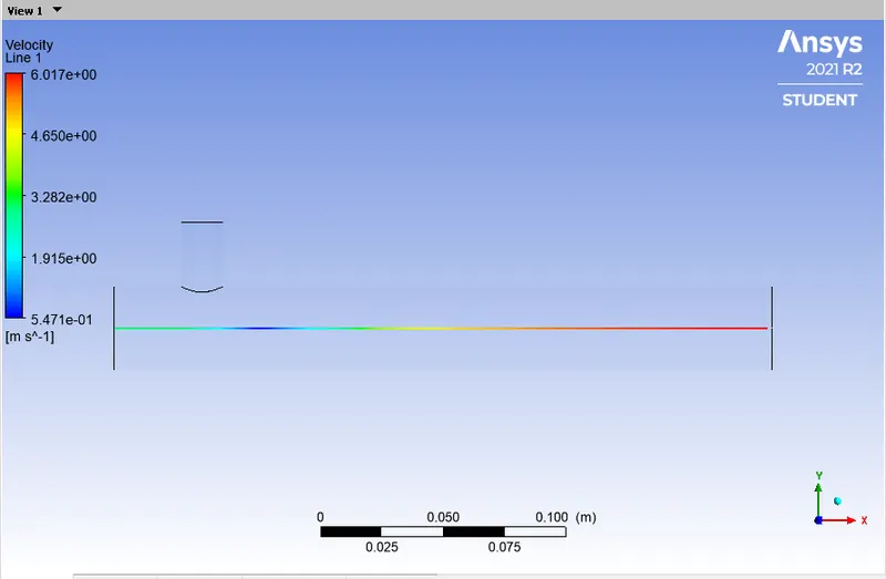
Velocity and Temperature along the pipe line plots
b) For the model k- Epsilon and momentum ratio is 4 where the hot inlet velocity is 3 m/s and cold inlet velocity 12 m/s
Residual graph Area weighted average of temperature graph
Standered deviation graph
Velocity and Temperature along the pipe contour plots
Velocity and Temperature along the pipe line plots
Compare between two cases of short length and long length:-
| Momentum ratio | number of cells | Average Outlet temperature | ||
| Short tee | 2 | 13014 | 30.25 | |
| 4 | 13014 | 25.53 | ||
| long tee | 2 | 15604 | 30.25 | |
| 4 | 15604 | 25.53 |
Effect of length and momentum ratio on results:-
- From the above calculation we can clearly conclude that there is no difference in the Outlet temperature means Outlet temperature is independent of length.
- but, Momentum ratio effects the Outlet temperature by increasing the momentum ratio the Outlet temperture is dropping or decresing.
- Or by increasing the momentum ratio the errors of residuals are increasing means it is going to effect the numerically accurance of the solution.
Conclusion:-From this project we can conclude that Temperature drops significantly due to increament in the velocity of cold fluid from the inlet and this is because of the hot and cold fluid meets at the T section and due to the high velocity of cold fluid flow is turbulent or we can say that turbulent mixing we got.
The temperature contour plots for short tee case shows that some high temperature flow without properly mixing at the tee section as compared in the long tee temperature contour plots shows high temperature mixing the rest flow throughly or properly. Therefore, we recomanded long tee high velocity for applications because in this low standered value means temperature is uniform.