Week 1:- Introduction to BiW and Fixtures Challenge
BODY IN WHITE (BIW)
Body in White (B.I.W.) refers to the welded sheet metal components which form the vehicles structure to which the other components will be married, i.e., engine, chassis, exterior and interior trim.
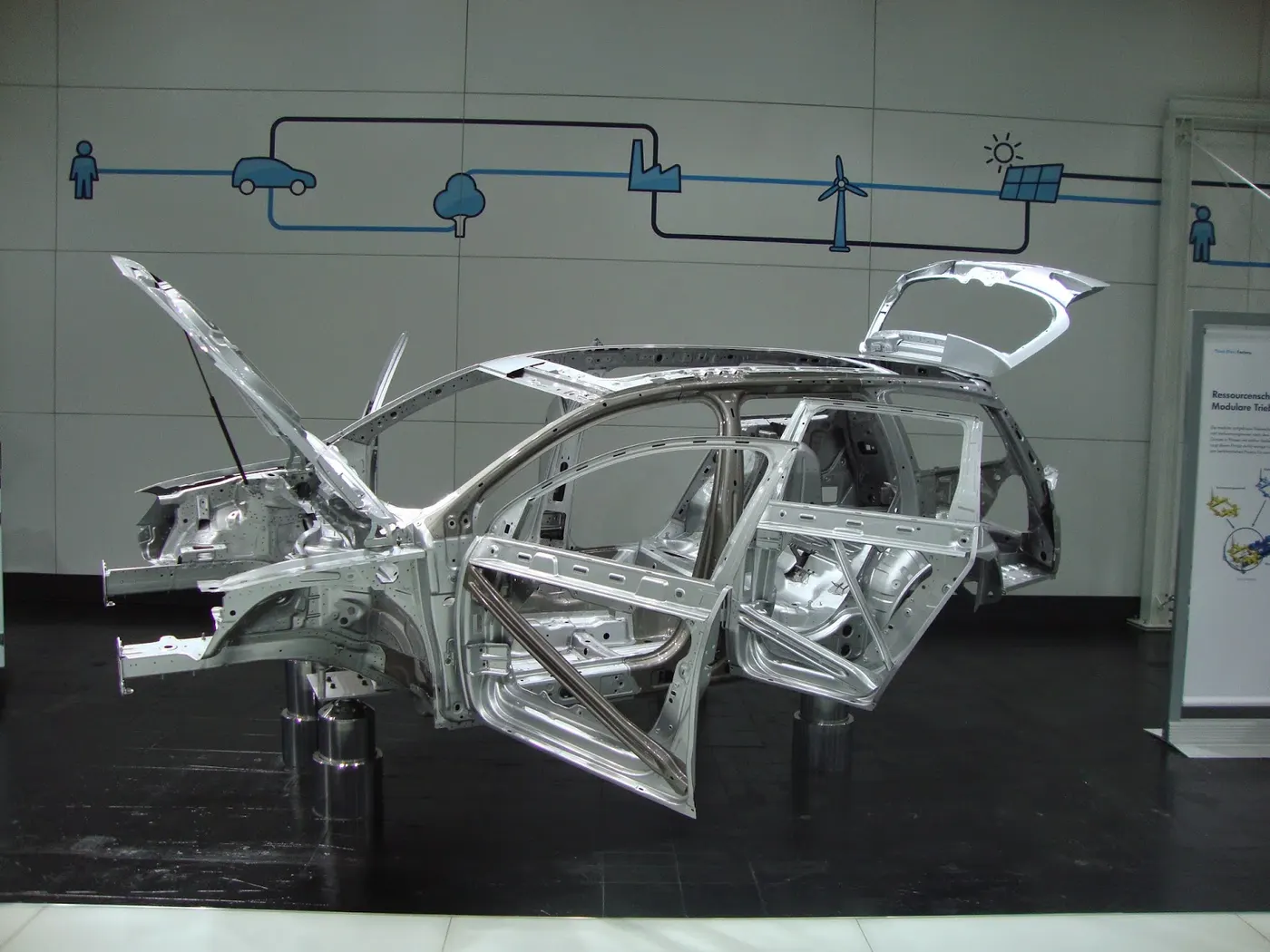
BIW refers to the stage in automotive design or automobile manufacturing in which the car body sheet metal (including doors, hoods, and side closers) has been assembled or designed but before the components (chassis, motor) and trim (seats, electronics items etc.) have been added. All activities in the production of a vehicle body before it goes to the paint shop are done in a body shop. The equipment used in the automotive industry has to meet the requirements related to the part’s weight and dimensions but also to the high production rates and high precision.
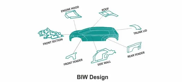
BIW Parts:
BIW parts are categorised as below
- Underbody structure
- Frond end structure
- Body side structure
- Closure
- Roof
BIW Nomenclature:
It is important to define common terminology for components to support common understanding between engineers.
The below figure illustrates all the parts and the nomenclature of the BIW parts.
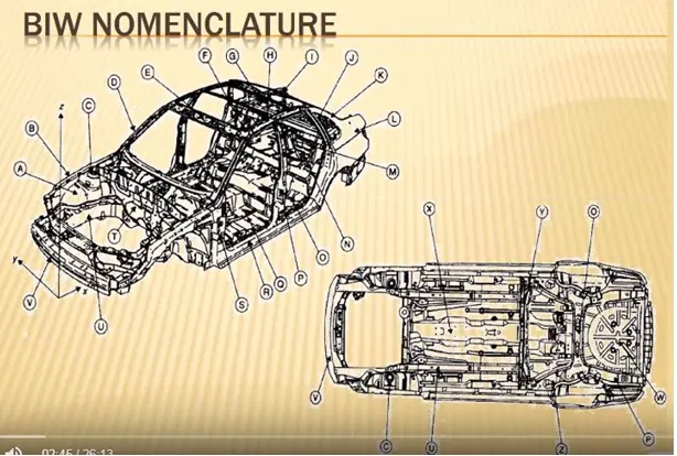
Here the comparision of part names btw the UK and US automobile industry are shown.
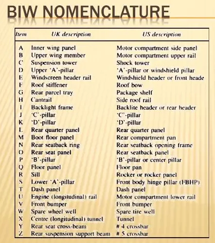
It can be observed that the name of the some parts are quite different between in US manufacturing industry and UK manufacturing industry.
BIW Fixture:
A device which is used to hold, locate and support the component in the manufacturing industry is called fixture. Fixtures ensure to provide the stability to the part when any process is being done on that part. That process can be welding, riveting, grinding, drilling etc.
In BIW fixture design Fixture works on 3-2-1 principle.
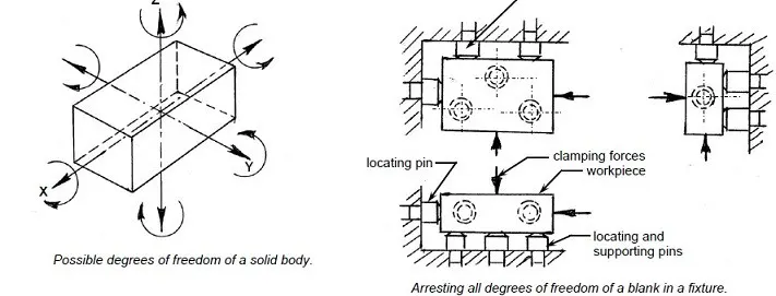
The 3-2-1 principle states that the six locators are sufficient to restrict the required degree of freedom of any workpiece. In this, motion is restricted using clamps and locators. A three-pin base can restrict five motions and six pins restrict nine motions.
[1] The workpiece is resting on three pins A, B, and C which are inserted in the base of the fixed body.
[2] The workpiece cannot rotate about the axes XX and YY and also cannot move downward.
[3] In this way, the five degrees of freedom 1,2,3,4 and 5 have been arrested.
[4] Two pins D and E are inserted in the fixed body, in a plane perpendicular to the plane containing pins A, B & C.
[5] Now the workpiece cannot rotate about the Z-axis and also it cannot move towards the left.
[6] Hence the addition of pins D and E restrict three more degrees of freedom, namely 6, 7, and 8.
[7] Another pin F in the second vertical face of the fixed body, arrests degree of freedom 9.
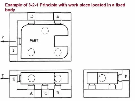
The above method of locating a workpiece in a fixture is called the 3-2-1 Principle.
Types of Fixture:
According to Flexibility Two types of Fixture:
• Modular Fixture
• Dedicated Fixture
Modular Fixture accepts the parts of different shapes and sizes. Modular fixtures became popular because of its performance on easy usage, versatility, and its adaptability to change in product. application of modular fixtures contributes Considerably to shortening the lead time and reducing the cost in small-volume production with versatile products.
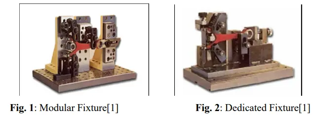
The dedicated fixtures are also important in manufacturing for advanced and precise part. Dedicated fixture is designed for a specific product, the designer can carefully make the design to not only meet the basic fixture requirements such as the locating accuracy, stability, stiffness but also optimally facilitate the operational requirements.
Now for automotive BIW line:
- Production fixtures- This fixtures are used for mass production purpose. It requires high consistancy through its operation to maintain the geometry of the parts so the material used are well tested for the hardness & asthetics. The quality for maintaining the dimensions & tolerances are also checked. The production fixtures needs to easy for mainatainace purpose. The fixture needs some maintainance after completing no.of operations. The time requires for assembly & disassembly should be as low as possible which saves lots of time.
- Preproduction operation fixtures(PPO)- These fixtures are design as a prototype fixture to check the feasibility of initial batch production & to check which things need to be improved before starting the production. These fixtures can be taken as the base fixtures which sets the benchmark & criteria which help us to rectify the errors that we could get from preproduction operation fixtures. In this many manual operations are involved, many engineers & quality related persons are required. It has the large cycle time as compare to production fixture. It requires lots of time & cost also.We have to maintain the cost of the car as low as possible so we directly go to the production fixture by considering standards, checklist to maintain the error free production.
- Checking fixtures- As name suggests these fixtures are used for the checking purpose. No operations like welding gluing or hemming are carried out in this fixtures. Tha gauges are used in these fixtures to get the dimensions & the tolerances part having & the data is compared with the designed dimensions to check wheather the part is ok or not. The geometry of the welded parts is also checked in this fixtures to ensure the parts maintain the required dimensions & geometry
Basically 3-2-1 principle is used to lock all six degree of freedom.
The 3-2-1 principle is a Component holding principle where three pins are located on the 1st principle plane, i.e. either XY, YZ, ZX. And two pins are located on the 2nd plane which is perpendicular to the 1st plane, and at last one pin on the plane which is mutually perpendicular to the 1st and 2nd planes.By using this method Componet can be arrested in all six degrees of freedom.
Assembly Line :
An assembly line is a process in which car panel/car body parts are joined as the semi finished assembly moves from one station to another station until the final product is produced.
In the process of joining in assembly line , panels are moved from one section to another sections.Those sections are called Station.
In BIW fixture designing we have various stations which are used to locate the panels so that joining processes can be done.
The BIW stations are further divided into following
1) Tool stations
2) Gripper stations
3) Stand station
4) Miscellaneous stations
1. Tool Stations:
- Geo Station:
In this station geometry of two parts are fixed. it can be either using welding or riveting . In this station precision and geomatry of the finished product is defined Locating pins have closer tolerence of 0/-0.15.
Suppose the hole dia of panel is 16mm then the pin dia minimum can be 15.85.
Diameter of locating pins should be lesser than the panel hole dia. So Tolrence in locating pin is given in negative value.
- Respot Station :
Once product comes out of the Geo Station and there are left out spots where spot welding or riveting is to be done. then it is moved to another station , that station is called Re-spot station.
These left out spots may be the due to clamp plan, cycle time,robot reach ability or any other various reasons.
In this station pins ahve tolrence upto 0/-0.28.
- Pedestal Station :
In this station , Pedestal gun is mounted on a tool and panel is manipulated manually or by robot to weld the panels.
Pedestal station is generally a Re spot station.
Re spot station and Pedestal station, both perform same kind of operation . but to decide whether to go for pedestal or a re-spot station some parameters needs to consider like cycle time, floor space, no. of welds, clamp plan, or size of the panel.
- Loading Station :
This station is used for loading of panel and same station is used to change the orientation of the if it is required in the upcomin station.
Sometime this station is used when Robots are unable to transfer panel from one station to another.
- Sealer Station :
In this station Sealant application is carried out.This process can be carried out manually or by using robots. Sealer is used in between two panels so that panels do not flatter due to friction.
- Marriage Station :
In this Station inner and outer panels are joined. In this station to avoid the imprssion on the outer panel(A class surface), copper strips are used in betweenn the weld tip and A-class surface.
2. Gripper Station:
A gripper is a device which enables the holding of an object to be manipulated. The easier way to describe a gripper is to think of the human hand. Just like a hand, a gripper enables holding, tightening, handling and releasing of an object. A gripper is just one component of an automated system. A gripper can be attached to a robot or it can be part of a fixed automation system.
Different grippers are used in BIW as follows,
A)Material handling gripper :
As the name suggest These grippers are used for material handling. These grippers can pick assemly from one station & will drop the assembly to another station.
B)Process grippers :
These grippers are used to carryout some specific process like gluing, welding, riveting etc. in addition with material handling. The gripper will goes under gluing stand in case of gluing process & will goes under the pedestal weld stand in case of welding process.
C)Combo Gripper :
Combo grippers are the one which can carry out multiple tasks like it can do material handling & also it can carryout some specific process like gluing, welding etc. as well. Its the combination of Weld gun + Gripper.
D)Dual Gripper :
These are two sided grippers. In case when we want one LH & one RH part, these grippers are used. It can handle the material from one station to another station
- Gripper + Gripper
3. Stand Station:
Stands are used to hold parts for storage or to perform operation on part. Different stands in BIW are
- Pedestal stands:
Weld gun is mounted on the fixed stand which is mounted to the floor permanently. The gripper can carry the panel under the stand to perform the operation.
- Gluing or Sealer stand:
Gluing gun or sealer gun is fixed to a stand which is fastened to the floor permanently.
- Docking Stand:
The robots have some limitations such as payload capacity or lack of space. In this case, we add docking stand to put some equipment which is not in use for current operation but will be required for next operation. Hence the robot can drop a gripper gun and pick next operation equipment to complete the task from docking stand.
- Date stamp stand:
Every manufactured product has some data to stamped or embossed on it like number, date etc. for future reference. This data is stamped on product by stamping device mounted on stamp stand.
4. Miscellaneous Station:
a) Curing: After gluing part needs some time to cool down, so we put assembly on some belts and it will take the panel to another station and meanwhile gluing will cool down.
b) Buffer stand: After the operations are completed, we can put assemblies in this stand which is buffer stock and can be transported from one station to another easily. They are also used as inventory when machines are undergoing maintenance.
c) Take out trolleys: It is used to take out some panels for inspection and to examine if the process is going on right or not between the cycle.
d) Conveyor: Conveyor is the rotating path which transports the parts to the next station which are kept over it.
BIW fixture Terminology:
- Mylars:
MYLAR is one kind of block that touches the panel and holds or clamps the panel. Mylars are always designed in CAR LINE. Mylar is also called NC(Numerically Controlled)Block. Mylars are mounted on any block or plate with Shimming, So that height of mylar can be adjusted accordingly at the assembly level. For ‘A’ class surfaces Nylon mylars are used. So that surface can be saved from scratches.
- SHIM:
Shim is a set of thin plates (2 mm, 1mm, 0.5 mm, 0.25mm) that are used to adjust the gap or used for a better fit. Shimming can be of thickness 5mm, 8mm, or 10mm. in case no proper fitting between mylar and Panel due to manufacturing errors then this error can be removed using shims. Shims are placed in the carline position so that gap can be adjusted in the required direction like X, Y, or Z.
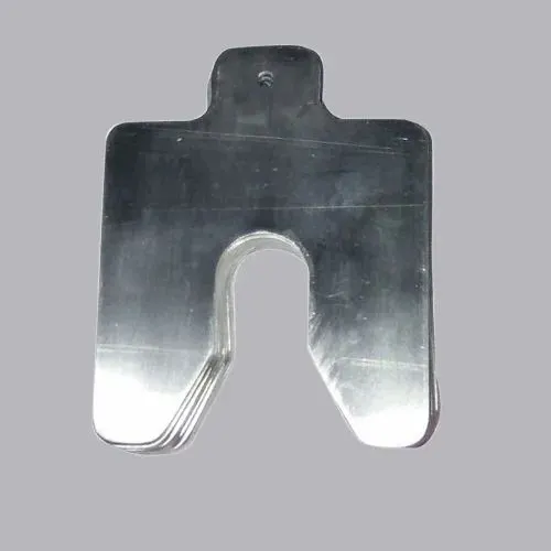
There are three types of shimming. These are one-way, two-way, and three-way shimming.
Number of shimming depends upon the NC cut angle and PIN angle with the car line.
If NC cut is less than 15 deg then mylar will have one-way shimming.
If NC cut is more than 15 deg in one direction then mylar will have a 2-way direction shimming
If NC has more than 15 deg angle in two directions then mylar will have 3-way directional shimming.
- Principle locating point (PLP):
These are the points which are used for the accurate location of the part to maintain the geometry of the assembly. There are lots of holes on the panel which are not accurate due to stamping operation. The PLP are defined in the drawing. The positional dimensions or relative dimensions are very precise in stamping & in fixtures also.
- Risers:
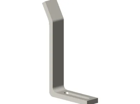
Risers are of different type like L-typer rises, Square tube riser etc. Riser is the manufacturing part which gives height to the assemblies.
- Blade:
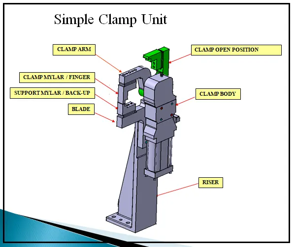
Blades are plates mounted on the riser. Other parts like cylinder, arms etc are mounted on the blade.
- Rough locators:
The operator can place the part in wrong orientation mistakanely. The rough locator will work as a guide while placing the part in the fixture & the part will be loaded in desired orientation. It is a part of fool proofing.
- Hardwares:
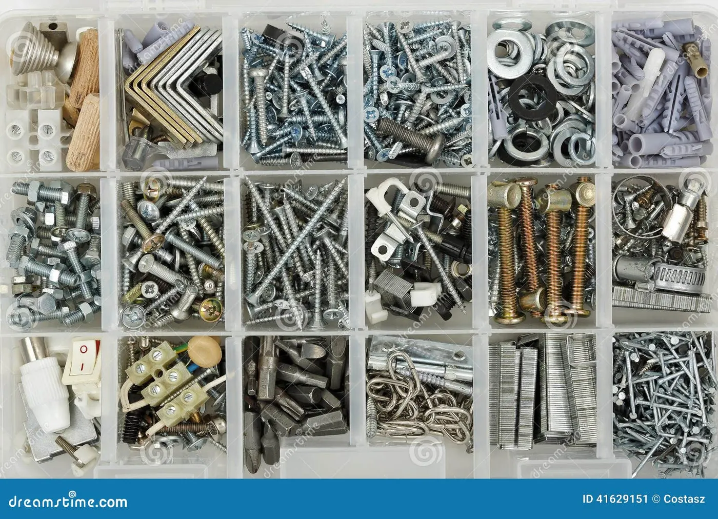
Hardwares are like the Hex head bolts, Allen Bolts, Hex nuts, Spring washers, Self locking nuts etc.
- CMM:
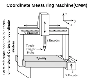
CMM stands for coordinate measuring machine. It is a device that measures the geometry of physical objects by sensing discrete points on the surface of the object with a probe. It generates report my comparing the data with the CAD file data.
- Unit:
The fixture is the assembly of different types of units to form a fixture. There are different units like pin unit, base unit, clamping unit etc.
- Number plates:
Number plate is the aluminium embossed plate placed on the each unit for easily recognising the unit.
- Name plate:
The data like manufacturing company name, fixture type, Fixture weight etc. is embossed on the plate & joined to the fixture.
- Clamp Arm:
Clamp arm is the part of clamp unit which moves over a axis. Over clamp arm the Mylars are mounted.
- Pivot:
It is a axis about which the clamp arm will rotates.
- Class A Surface/Skin surface:
The outer panels of the car like hood, door, backdoor, fender,roof etc. are visible to the customer. The outer panels should be asthetically very good. No any scratches or dent is acceptable over it. While designing the fixture to the skin surface the clamping material should be soft, so that it could not able to left any impression or dent over skin. generally nylon or pu material is used for clamping purpose.
- Reed switches & sensors:
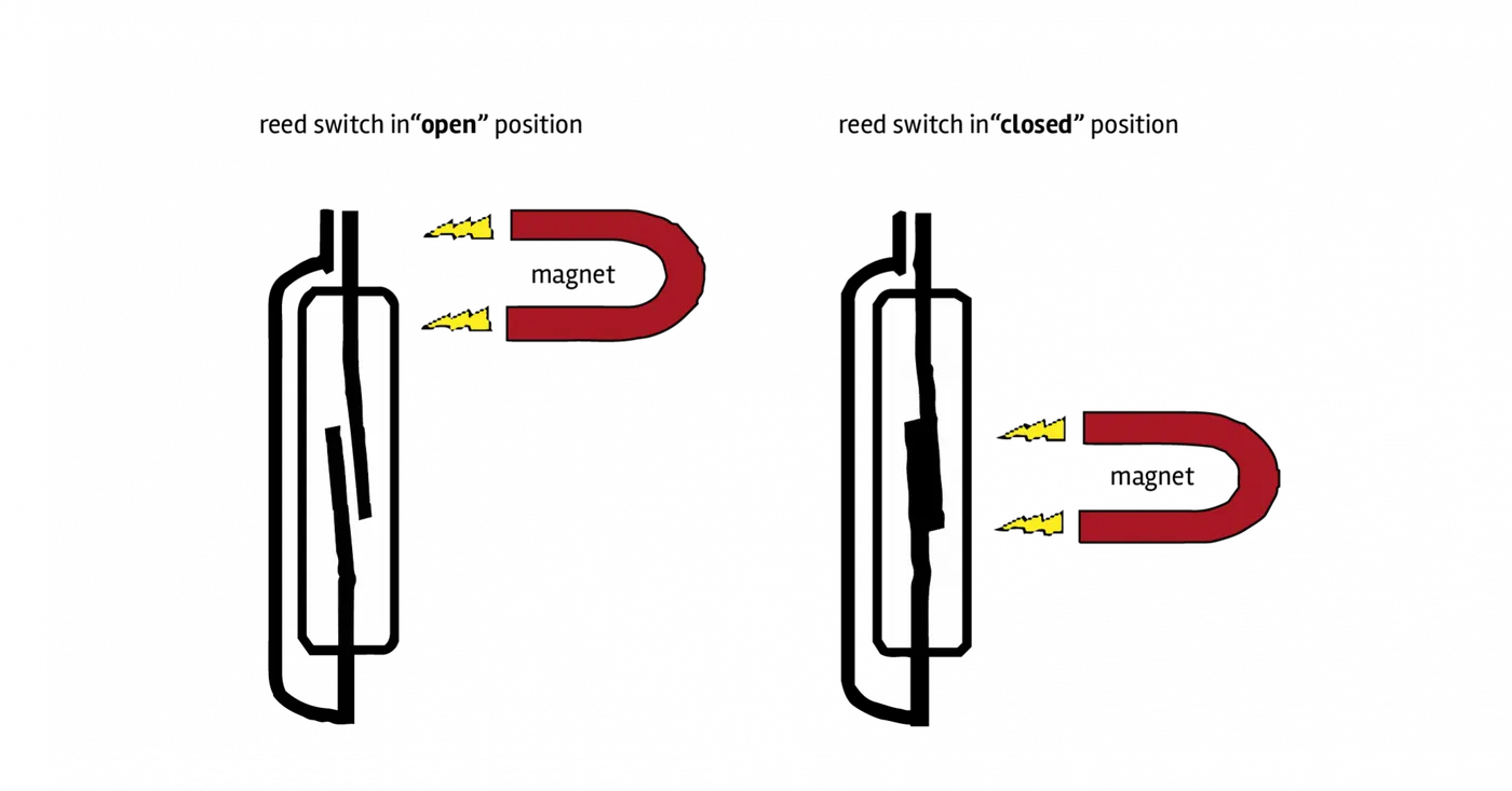
These are the electric componnents used in automated fixtures. The reed switch is an electrical switch operated by an applied magnetic field. The detects the panel is loaded or not is done by sensors.