To prepare a detailed project report and analysis of EV VEHICLE MODEL BASED ON DC MOTOR.
AIM- To prepare a detailed project report and analysis of EV VEHICLE MODEL BASED ON DC MOTOR. As we know the Simulink environment is best for testing, analysing and designing of new and innovative changes of physical model as it cost very less compare to the real-world model testing. Our aim is to understand and prepare detailed report of the Vehicle model in order to learn how MATLAB Simulink models work.
COMPONENT REQUIRED-
DASHBOARD- Knob, Circular gauge.
INPUT- Drive cycle, Signal builder block, Constant block, Multiport switch, Longitudinal driver.
CONTROL- Controlled voltage source, Controlled voltage PWM, H-Bridge converter, Current
Sensor, Battery, Controlled current source, PMDC motor.
VEHICLE BODY- Simple gear, Tyre, Vehicle body block.
SOP- Gain block, Integrator, Subtract block.
RESULT- Go/From blocks, Integrator block, Scope's, Torque and Speed vector file, Annotation Plot, solver configuration.
THEORY-
PMDC MOTOR-
A PMDC motor is a DC motor with permanent magnet in replacement of Electromagnet. The total control over motor can be done by controlling armature voltage. DC motor uses Lorentz law for converting electrical energy to mechanical energy. Lorentz law states that “When kept in a magnetic field, a current-carrying conductor gains torque and develops a tendency to move.” The direction of force can be determined by Fleming’s left-hand rule.
The Lorentz force is given by-
F=ma
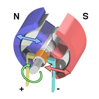
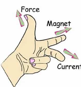
PMDC motor having yoke attached with permanent magnet and having armature winding mounted on rotor and have a mechanical device so called commutator for converting DC to AC. The permanent magnets are mounted in such a way that the N-pole and S-pole of each magnet are alternatively faced towards armature as shown in the figure below. That means, if N-pole of one magnet is faced towards armature then S-pole of very next magnet is faced towards armature. Due to permanent magnet and commutator these motors are not suitable for high power applications.
Equivalent Circuit of Permanent Magnet DC Motor or PMDC Motor
As in the PMDC motor, the field is produced by a permanent magnet, there is no need for drawing field coils in the equivalent circuit of a permanent magnet DC motor.
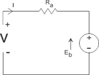
The supply voltage to the armature will have armature resistance drop and the rest of the supply voltage is countered by the back emf of the motor. Hence the voltage equation of the motor is given by,

Where, I am armature current and R is armature resistance of the motor. Eb is the back emf and V is the supply voltage.
Motor Model- In this very simple motor model, the mechanical parameters are completely ignored. On the electrical side, the motor basically contains a number of inductors, that move in a magnetic field. The inductors themselves of course have an inductance, and some internal resistance. Their movement in the field will generate a voltage – called generator voltage and denoted by Vg – across the inductors. From this description, the following model can be drawn:
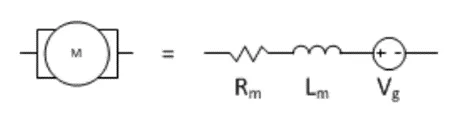
The generator voltage (Vg) depends only on the speed by which the inductors move in the field, in other words on the rotational speed of the motor.
H-BRIDGE CONVERTER-
H bridge converter is most popular converter among all converters for its simple design and high efficiency applications. H-Bridge uses for converting AC-DC, DC-AC, DC-DC power with controlled input. The name is derived from its common schematic diagram representation, with four switching elements configured as the branches of a letter "H" and the load connected as the cross-bar.
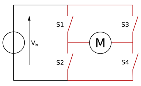
H-Bridge is popular for control of DC motors with the help of PWM control signals. In general, an H-bridge is a rather simple circuit, containing four switching elements, with the load at the centre, in an H-like configuration:
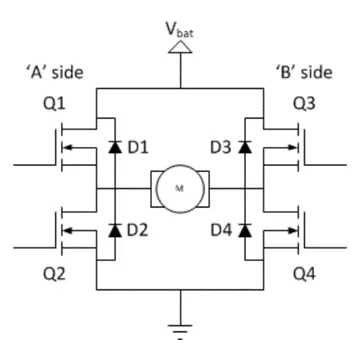
The switching elements (Q1, Q4) are usually bi-polar or FET transistors, in some high-voltage applications IGBTs. Integrated solutions also exist but whether the switching elements are integrated with their control circuits or not is not relevant for the most part for this discussion. The diodes (D1, D4) are called catch diodes and are usually of a Schottky type.
The top-end of the bridge is connected to a power supply (battery for example) and the bottom-end is grounded.
In general, all four switching elements can be turned on and off independently, though there are some obvious restrictions.
Though the load can in theory be anything you want, by far the most pervasive application if H-bridges is with a brushed DC or bipolar stepper motor (steppers need two H-bridges per motor) load. In the following I will concentrate on applications as a brushed DC motor driver.
Static Operation
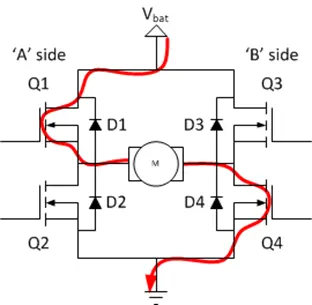
The basic operating mode of an H-bridge is fairly simple: if Q1 and Q4 are turned on, the left lead of the motor will be connected to the power supply, while the right lead is connected to ground. Current starts flowing through the motor which energizes the motor in (let’s say) the forward direction and the motor shaft starts spinning.
If Q2 and Q3 are turned on, the reverse will happen, the motor gets energized in the reverse direction, and the shaft will start spinning backwards.
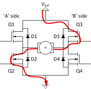
In a bridge, you should never ever close both Q1 and Q2 (or Q3 and Q4) at the same time. If you did that, you just have created a really low-resistance path between power and GND, effectively short-circuiting your power supply. This condition is called ‘shoot-through’ and is an almost guaranteed way to quickly destroy your bridge, or something else in your circuit.
Drive modes
Previously we’ve only considered static operation, when nothing was changing. If less than full-speed operation is intended the switches are controlled in a PWM fashion. A PWM signal has two phases, the ‘on-time’ and the ‘off-time’ as I’m calling them in the diagram below:
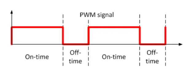
It is a periodic signal, with a constant frequency. The information content – that is used to change the operating parameters of the bridge – is the ratio between the on-time and the off-time. The various drive modes differ in how the switches are set during the on-time and the off-time.
So, by means of PWM signals we control the H-Bridge, therefore a pulsating type variable DC can be obtained. This signal further can be optimise using filter for smooth DC operations but we take pulsating type DC for model simplification.
STATE OF CHARGE-
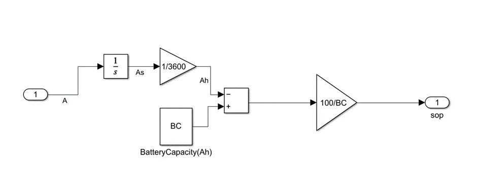
It is also referred as SoC, this is a characteristic of a battery which represents the power available in a particular state of battery. State of charge (SoC) is the level of charge of an electric battery relative to its capacity. The units of SoC are percentage points (0% = empty; 100% = full).
Usually, SoC cannot be measured directly but it can be estimated from direct measurement variables in two ways: offline and online. In offline techniques, the battery desires to be charged and discharged in constant rate such as Coulomb-counting. This method gives precise estimation of battery SoC. Or we can measure total charge loses with the help of integrating output current of the battery, representing the total charge lose and subtract it from the total Battery Capacity (BC).
VEHICLE BODY-
Vehicle body is in direct contact with the environment so various terrain condition have to simulate like inclined plane and wind effect and drag forces.
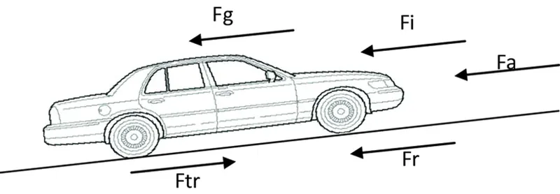
the normal face of tire indicates the power transfer direction from the engine and all other forces like friction, wind and gravitational forces depends upon terrain and environmental conditions.
BLOCKS-
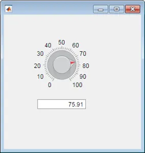
KNOB AND CIRCULAR GAUGE- These blocks are used for greater real time simulation experience. In infinite simulation time model this Knob and Circular gauge are really helpful to giving real time input and analysing data. We use two Knob for throttle input and brake input and two Circular Gauge for Engine RPM and speed of vehicle.

CONSTANT- It is used for giving input to a model as a constant and can be connected from Knob.
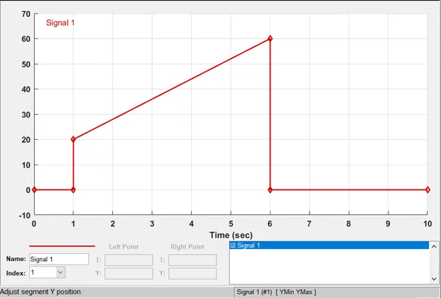
SIGNAL BUILDER- Signal builder block is used to build a signal based on a given input and here we use a trapezoidal signal having strength from 1 second to 6 seconds then it turns to zero.
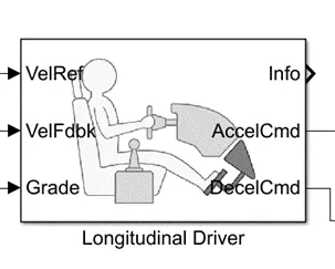
LONGITUDINAL DRIVER- It is a Simulink block that represent a driver using its own mind for controlling the vehicle with the help of acceleration and brake paddle. It is popular for testing EV models as it models a driver as a real-world identity.
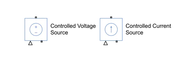
CONTROLLED VOLTAGE & CURRENT SOURCE- It generates voltage/current corresponding to the input signal given to it.
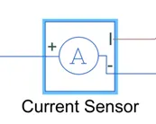
CURRENT SENSOR- It measures current flowing through its positive to negative terminal and give the corresponding value to “I” port in amps.
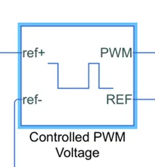
CONTROLLED VOLTAGE PWM- The block showing is responsible for generating controlled PWM signal as per input voltage. If there are rated voltage is given to this block, the block will generate 100% duty cycle signal and if input voltage is zero then the duty cycle of output signal will be 0%.
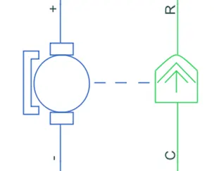
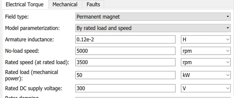
DC MOTOR- It represent the electrical and torque characteristics of DC motor.it is brush type DC motor that can be modelled either by equivalent model parameters or rated capacity of machine. Here we use Permanent magnet motor with rated capacity as follows,
INERTIA- Inertia is a physical property of material which exhibit opposition for change in motion and it modelled as a simscape block for modelling of mechanical element.

SIMPLE GEAR- It represent simple gear set have a nominal gear ratio as Nf/Nb.
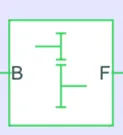
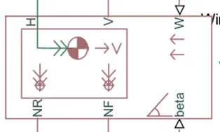
VEHICLE BODY- It represent Simulink level mathematical model of vehicle body, which converges the effect of wind and inclination of operation plane. Its ports are following,
1 NR, NF- normal faces of rear and front wheels
2 H- mechanical translational conserving port
3 V- velocity of vehicle
4 W- wind velocity
5 beta- inclination angle
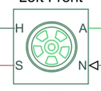
TYRE- This block represents the detailed level model of rubber-based tyre with including load capacity, max velocity, frictional coefficient, inertia and slip of the tyre. there are four ports namely, A, N, S, H which indicates mechanical rotational conserving port, normal face, slip, mechanical translational conserving port.
INTEGRATOR- It integrate input signal with respect to time.
SCOPE- It plots input amplitude with respect to time.
SOLVER CONFIGURATION- Every physical Simscape model needs solver configuration, based on its property, model is solved through different numerical methods, for example Euler rule.
OPERATION-
As we give input to the model by means of either Knob, Signal builder block or Drive cycle, The longitudinal driver block will compare the input signal with the actual vehicle speed and then apply the acceleration and brake accordingly to meet the desirable condition, which is nothing but the reference input. The model shows below to understand the step wise operation,
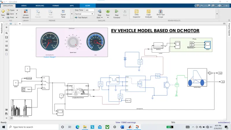
The input of the H-Bridge converter is given by Voltage controlled PWM generator along with the Controlled voltage source, therefore corresponding output is generated and the voltage is directly fed to a DC motor. In addition, we use a self-powered H-Bridge so for estimation of SoC we use output current of the H-Bridge as a self-powered input for SoC calculation block.
We use H-bridge simulation as average model so that our simulation runs fast and same for PWM generator.
The output of DC motor is given to a Simple gear set then Vehicle body came into picture. Take a look on the Vehicle body block,
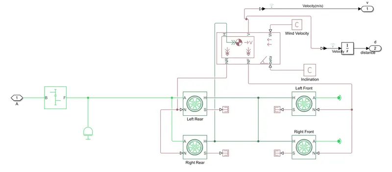
Here we see four wheels arrangement, which have same translational velocity component, connected to vehicle body blocks "H" port, as it mounted on the same frame as vehicle body. The rotational conserving ports(A) of the rear wheels is fed by simple gear (previous block), and front wheels 'A' ports ends with rotational free end. and the assumption to this model is that its tyre slip is always zero.
The wind velocity(W) and inclination angle(beta) is given to this model as constant so it doesn't vary with time.
The velocity is directly measures by port V of the Vehicle Body block, which is in m/s so we convert the velocity to km/h by multiplying it by “3.6” and to measures distance travel by the vehicle, we use integrator to integrate velocity that results in distance travelled by the vehicle.
RESULTS-
Here we can feed input in real time speed data using a Knob or we can use signal builder block for giving input of speed values over different time, there are third option available that is Simulink drive cycle block, it is used by manufacturer for testing purposes.
For this case we will use FTP75 Drive cycle for 340 seconds and see the model behaviour.
First, we need to take a look at input speed and corresponding vehicle speed,
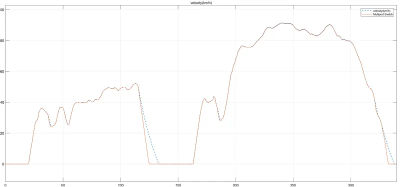
Here we see the orange line representing the drive cycle input and dotted blue lines indicating actual vehicle speed that is following the drive cycle with some abnormality, this is due to vehicle inertia.
Here speed increase from 20 second and then after varying a little, it suddenly drops to 0 in about 125sec. the whole drive cycle is corresponded to real life situation so passing the test on this cycle is very crucial for any EV model.
After analysing the drive cycle and vehicle speed, we have to consider SoC and current taken by the vehicle in order to estimate battery capacity and corresponding maximum current taken ability. In this case its roughly 350amps, therefore we need to make changes to the model because its not feasible to design such battery.
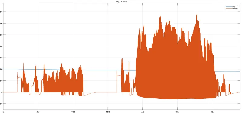
So, either we increase the voltage capacity of motor or make some changes to the vehicle body so it doesn’t require too much torque for handling vehicle.
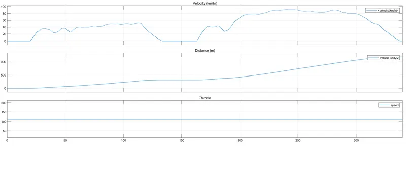
After observing the SoC, we can say in the braking period the current become negative due to regenerative braking, therefor battery charges in this reason with the inertia of vehicle. We take BC=20Ah at 100% charge condition. For such a short duration of running, the battery still has 88% of battery left after vehicle runs for a distance of 1195m.
Now we move to see some basic parameters like velocity and distance of vehicle over 340 sec of time period. It is given by,
CONCLUSION-
We make a DC motor-based EV Vehicle model in Simulink environment and successfully did analysis of the results. The analysis purpose is to find imperfection in design, that is identified and we share comment so that future model can be modified.