Project
AIM- To prepare a detailed project report and analysis of BAJA ATV Vehicle simulation model. As we know the simulink enviroment is best for testing, analysing and designing of new and innovative changes of physical model as it cost very less compare to the real world model testing. Our aim is to understand and prepare detailed report of the Vehicle model in order to learn how matlab-simulink models work.
COMPONENT REQUIRED-
DASHBOARD- Knob, Circuler gauge.
SIMSCAPE MODEL- Constant input block, Generic Engine, Engine Sensor, Signal Builder, CVT, Simple Gear, Vehicle Body.
CVT- Variable ratio gear, Inertia block, Rotational Motion Sensor.
VEHICLE BODY- Vehicle Body block, Tyre, Double shoe Brake, Inertia block.
RESULT- Go/From blocks, Intergator block, Scope's, Torque and Speed vector file, Annotation Plot, solver configuration.
THEORY-
GENERIC ENGINE- A four stoke engine is Internal combustion(IC) engine that converts fuel's chemical energy into mechanical rotation with the help of piston and crankshaft. There are four strokes of piston for a single time intake of fuel, therefore it is called the four stroke engine. Every stroke have their special work, four strokes will give higher efficiency as it complete four cycle of piston movement for only one time fuel input.
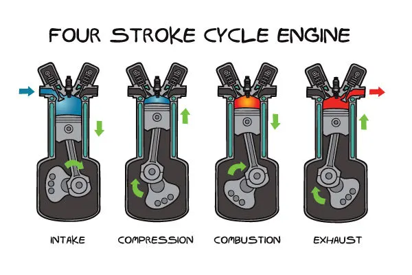
generally first stoke is intake stroke, in which fuel and air is taken into the combustion chamber, then the second stroke(compreession) is done by piston itself, this result in temperature rise of the air and fuel. the third stroke(combustion) is the power stroke as it is the only stroke among four stroke which gives power to crankshaft, In this stage fuel is ignited by spark plug(petrol) or by heat(diesel). and the last stroke also called as exhaust is done so that burn fuel can go out of the combustion chamber.
CONTINUOUSLY VARIABLE TRANSMISSION- Continously Variable Transmission is also known as CVT is an new technology which provide variable gear ratio for large speed range and upto 300HP if specially design steel belt is used. CVT gives variable gear ratio in continous mode so that no jerky operation will occure, this results in high efficiency and better traction of Vehicle
.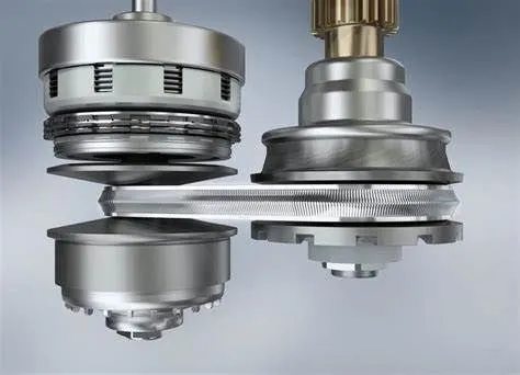
The CVT consist of two V-shaped pully with an belt arrangement between them, the pully consist a movable and a fixed side so that diameter of pully can adjust by adjusting the moving side of pully. Here we need only one controllable pully because the other pully gonna adjust its diameter by its own as belt length doesn't change.
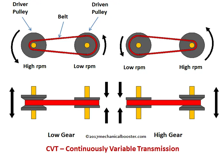
the gear ratio (dia of driven pully/ dia of driver pully) can be adjusted in two way-
1. Centrifugal rollers
2. External oil pressure
In most cases centrifugal rollers are used as it is simple and have tendency to auto adjust gear ratio of CVT according to the speed of vehicle itself.
VEHICLE BODY- Vehicle body is in direct contact with the enviroment so various terrain condition have to simulate like inclinde plane and wind effect and drag forces.
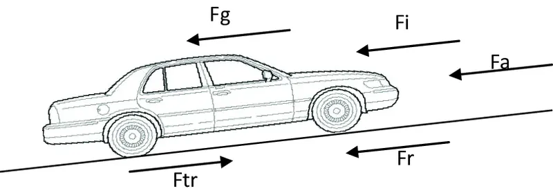
the normal face of tire indicates the power transfer direction from the engine and all other forces like friction, wind and gravitational forces depends upon terrain and enviromental conditions.
BLOCKS-
KNOB AND CIRCULAR GAUGE- This blocks are used for greater real time simulation experience. In infinite simulation time model this Knob and Circuler gauge are really helpful to giving real time input and analysing data. We use two Knob for throttle input and brake input and two Circular Gauge for Engine RPM and speed of vehicle.
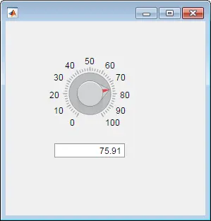
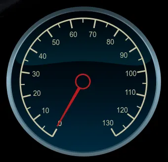
CONSTANT- It is used for giving input to a model as a constant and canbe connected from Knob.
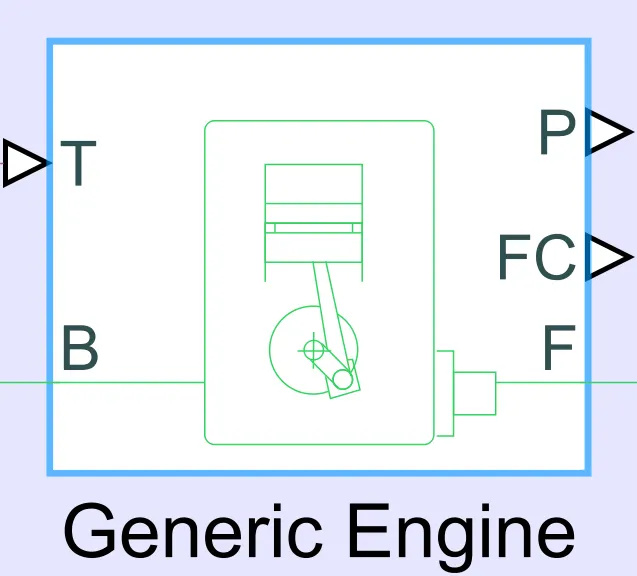
GENERIC ENGINE- It is a simple simscape block representing a four stroke petrol/diesel engine with basic parameters, it is useful for analysis purposes and have input signals as throttle input (T) and output port as Base(B) and Follower(F) indicating crankshaft. there are two more port namely power(P) and Fuel Comsumption(FC) for indication power in watts and fuel comsumption as per model specification.
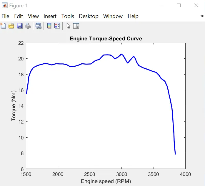
The characterstics of speed torque of the engine modelled here is given by a vector dataset[70*1] from the workspace. we can plot this characterstics as speed-torque graph from the annotation properties of the simulink model. we write a code for ploting this data set under the click function of annotation property.
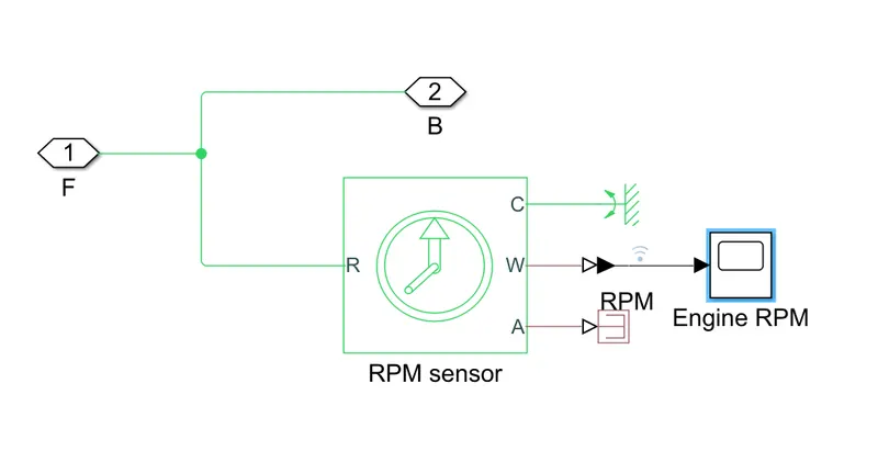
ENGINE SENSOR- Engine sensor block consist of an ideal rotational motion sensor.
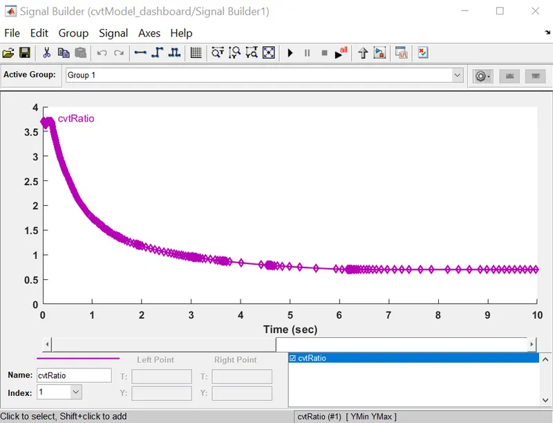
SIGNAL BUILDER- Signal builder block is used to build a signal based on a given input and here we use timeseries .mat file for giving input as cvtRatio.
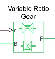
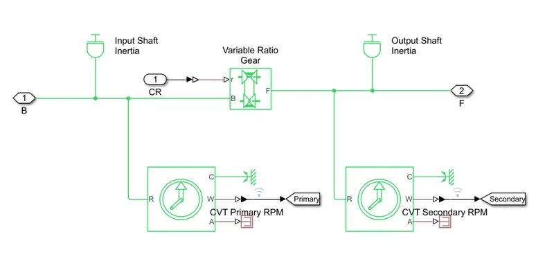
VARIABLE RATIO GEAR- It represent the CVT model, as it gives variable gear ratio as per given input "r".
ROTATIONAL MOTION SENSOR- It is used for sensing mechanical rotational physical quantity like speed, angular position.
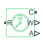
INERTIA- Innertia is a physical property of material which exibit opposition for change in motion and it modeled as a simscape block for modelling of mechanical element.
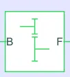
SIMPLE GEAR- It represent simple gear set have a norminal gear ratio as No/Ni.
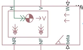
VEHICLE BODY- It represent simulink level mathematical model of vehicle body, which converges the effect of wind and inclination of operation plane. Its ports are followong
1 NR,NF- normal faces of rear and front wheels
2 H- mechanical translational conserving port
3 V- velocity of vehicle
4 W- wind velocity
5 beta- inlination angle
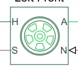
TYRE- This block represent the detailed level model of rubber based tyre with including load capicity, max velocity, frictional coefficient, inertia and slip of the tyre. there are four ports namely, A, N, S, H which indicates mechanical rotational conserving port, normal face, slip, mechanical translational conserving port.
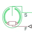
DOUBLE SHOE BRAKE- It represent a drum brake simscape model with a single input port which is connected with brake input.
INTEGRATOR- It integrate input signal with respect to time.
SCOPE- It plots input amplitude with respect to time.
SOLVER CONFIGURATION- Every physical simscape model needs solver configuration, based on its property, model is solved through different numerical methods, for example euler rule.
OPERATION-
As we give input to the model by means of Knob with taking simulation time infinite, we see engine starts and vehicle speed increases from zero to a certain value that depends upon the throttle input and brake input. This throttle input is given to a Generic engine that runs the crankshaft and its output(mechanical rotation) reflects on the "F" port, then its output is further given to engine sensor for analysis purpose.
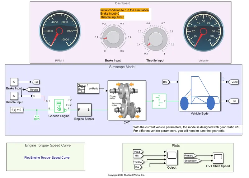
The Engine Sensor block consist of an ideal mechanical rotational sensor as shown below and it bypass the Engine output to CVT subsystem.
The input to CVT is given by a signal builder block as cvtRatio input, this is taken from a .mat time series file in this model.
Now we look into the mask of subsystem "CVT", this have input as cvtRatio(port CR) and from the Engine Sensor(port B) that is given to a Variable Ratio Gear. the primary and secondary speed of the CVT is measured though two different motion sensors. The Variable Ratio Gear transfers speed and torque of engine to the driven shaft as per the CVT ratio given to this block.
The output of CVT(port F) is given to a simple gear having gear ratio(Nf/Nb)= 10, which transfer this power to Vehicle Body subsystem.
Now we look under the Vehicle Body subsystem.
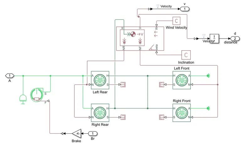
Here we see four wheels arrangement which have same transational velocity component, connected to vehicle body blocks "H" port, as it mounted on the same frame as vehicle body. The rotational conserving ports(A) of the rear wheels is fed by simple gear(previous block), and front wheels 'A' ports ends with rotational free end. and the assumption to this model is that its tyre slip is always zero.
The wind velocity(W) and inlination angle(beta) is given to this model as constant so it doesn't vary with time.
The velocity is directly measures by port V of the Vehicle Body block and to measures distance travel by the vehicle, we use integrator to integrate velocity that results in distance travelled by the vehicle.
RESULTS-
We first run the model then make changes with respect to time by means of Knob, which is available in the dashboard. I run this model as from rest and initial inputs are,
Throttle= 1, Brake= 0.
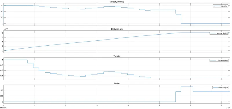
so I starts with Throttle input to vary as decreassing and increasing value to observe the vehicle speed changes, and at last i applied brakes this, results in total stopage of vehicle(V=0). then distance become constant as there is no further increament of velocity.
Now we observe the primary and secondary shaft speed of the CVT for better understanding of the speed variation between driver shaft and driven shaft
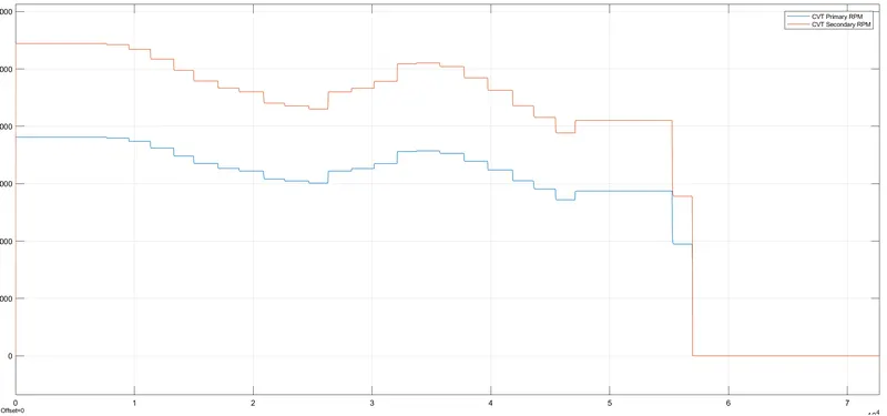
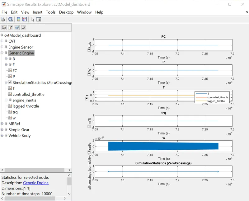
We can further analyse the simulation by inspecting the simscape result in the review section, the simscape result window can show the data related the inhereint properties of the simscape block that can only viewed by the simscape result.
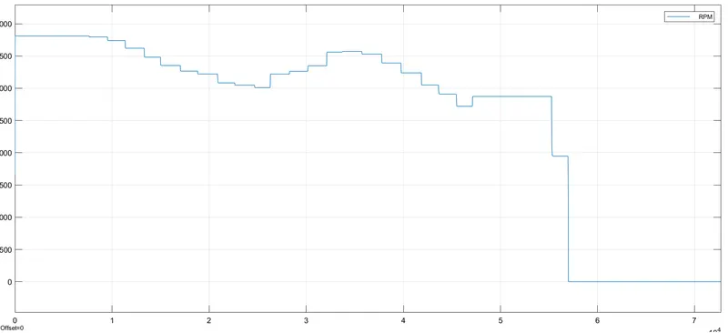
Engine Sensor output in RPM is given by-
CONCLUSION-
We perform an system level simulation of BAJA ATV Vehicle model and prepared a detailed report on the operation of the Vehicle with the help of matlab simulink model.