To implement control logic of a "washing machine" using state flow and To make a Simulink chart for the "Gear shift" logic.
AIM:
- To implement control logic of a “washing machine” using Stateflow.
- To make a Simulink chart for the “Gear shift” logic as per below conditions:
Speed Range(kmph) Gear
0 to 15 1
16 to 25 2
26 to 40 3
41 to 60 4
Above 61 5
OBJECTIVES:
1. i) If the power supply is available, the system gets activated.
ii) If the Water supply is not available, stop the process & indicate through LED
iii) Soaking time should be 200s followed by Washing time of 100s.
iv) Then rinsing happens for next 20s & dryer runs for 50s
After all the processes have completed turn on the finished LED
2. To display the gear number.
1.DESCRIPTION :
Washing machine : Washing machine s the machine used to wash the various types of clothes without applying any physical efforts.
Types of washing machine : 1. Top loading washing machine
2 . Front loading washing machine.
Parts of the washing machine:
- An inner drum: This is where we put the clothes when we’re ready to wash. We’ll notice this drum rotates a bit when we touch it and there are a lot of holes punched into the drum. These allow the water to come in and wash the clothes.
- Paddles: These are ridges that lie on the edge of the drum and help move clothes around while being washed.
- Agitator: These are more common in top load machines and is a paddle in the middle that helps turn the clothes around in the soapy water.
- The outer drum:This is not obvious when you look inside the washer, but there is another drum that holds the water while the inner drum or agitator rotates. This part is completely water tight to prevent your machine from leaking all over the bathroom or kitchen!
- Thermostat and heating element:These control the temperature of the water and heats up the water to the specified temperature.
- Pump: This removes the water from the drum after the wash.
- Programmer:This controls the washing machine through all the steps from washing to rinsing and spin drying.
- Pipes and valves:These allow the water in and out of the washer
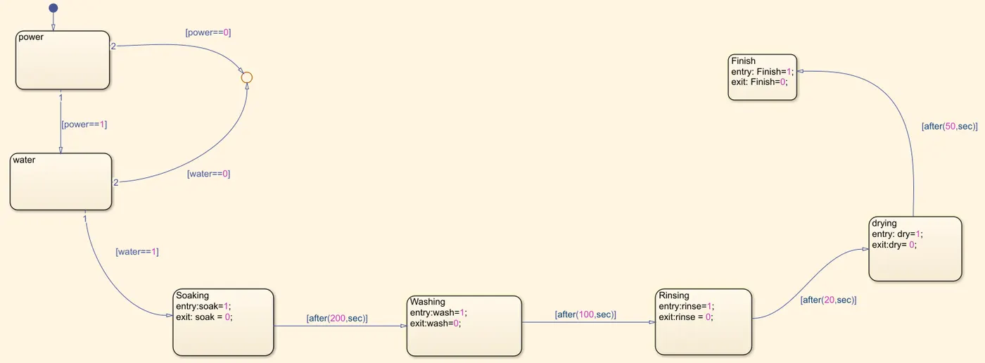
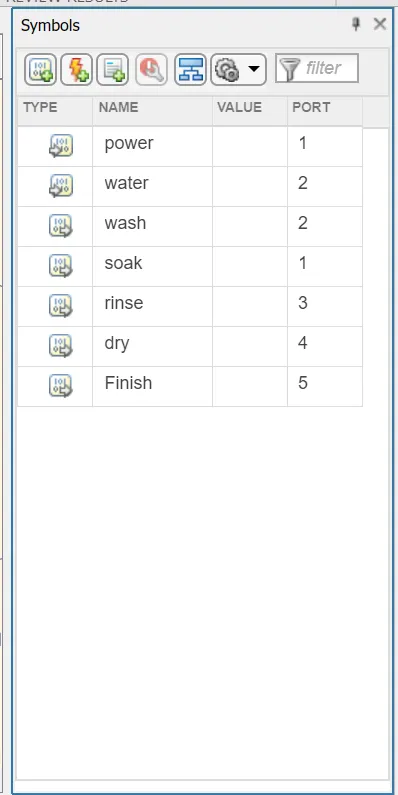
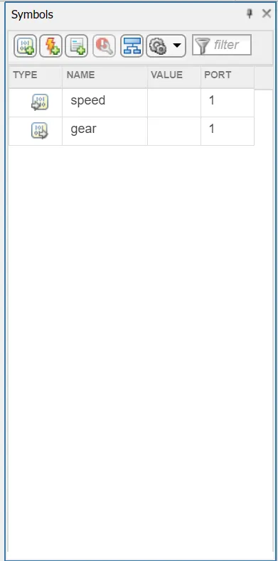
The input and output values for chart are selected through symbols pane.
EXPLANATION :
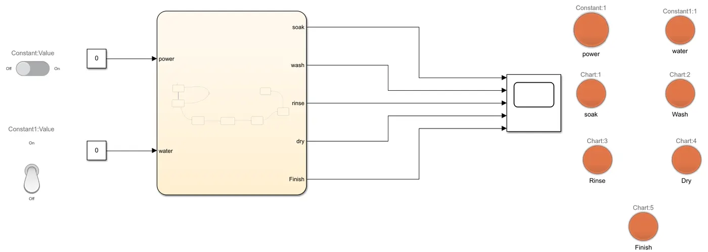
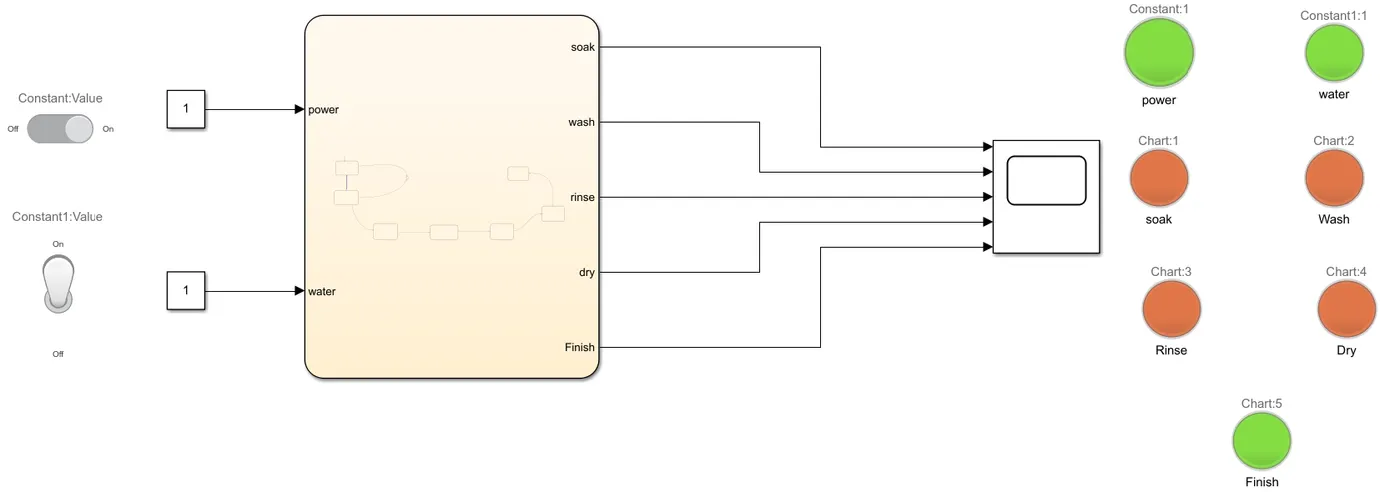
- The power supply and the water supply are defined by constant values '0' and '1'.
- Toggle switch and normal switch are used just to differentiate while using power and water supply.
- Lamps are activated based on the given input values i.e., the process which are running.
- Stateflow chart: A chart flow is created to define the washing machine state flow process.
- When power and water supply values are '1' the signals gets ito the state flow and the process will be started.If values of power and water supply is '0' the process will not be started and if any of those values is '0' the process will be terminated.
- When power and water supply value is '1' the process begins and the soaking process will be done upto 200 secs.
- After 200 secs the soaking pwill be stopped and washing process will be done for the next 100 secs.
- After the time value of 300 secs, next rinsing process will be started and will be completed after 20 secs i.e., after 320 secs.
- Finally , drying process will be for 70 secs and after 370 secs the washing machine will be stopped automatically.
- Each process will be indicated through lamp for the given time limits.
Results:
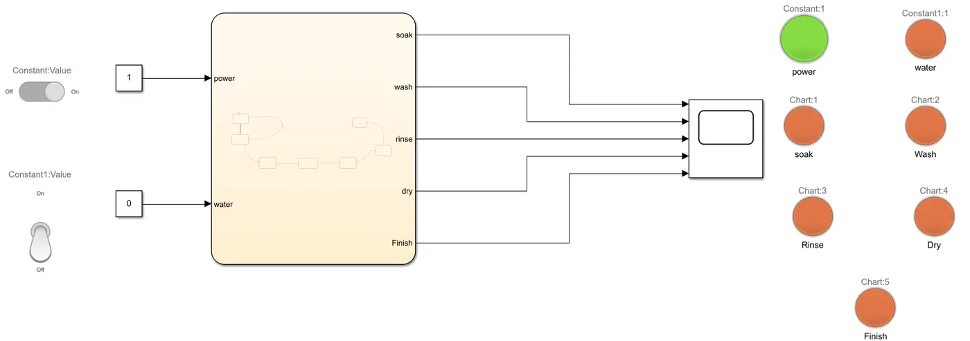
- A simulink model when both power supply and water supply are OFF .
At t = 10secs, Power: ON and the system gets activated and Water:OFF, the process is stopped.
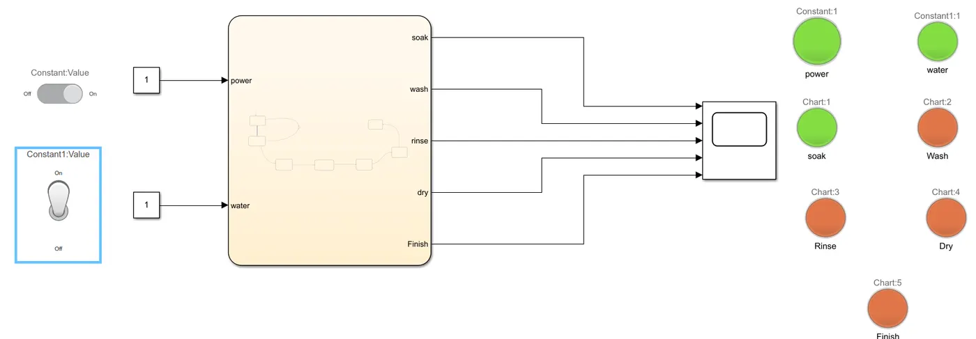
At t=199 secs, Power:ON,Water:ON and the soaking process is started.
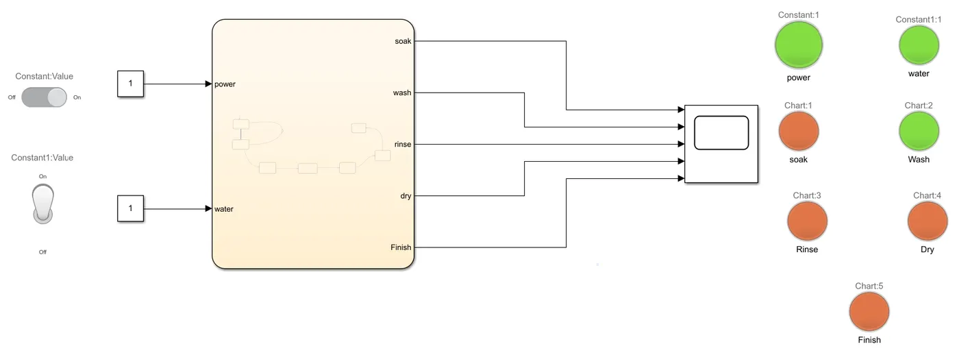
At t = 270 secs, Power:ON,Water:ON and the washing process is started.
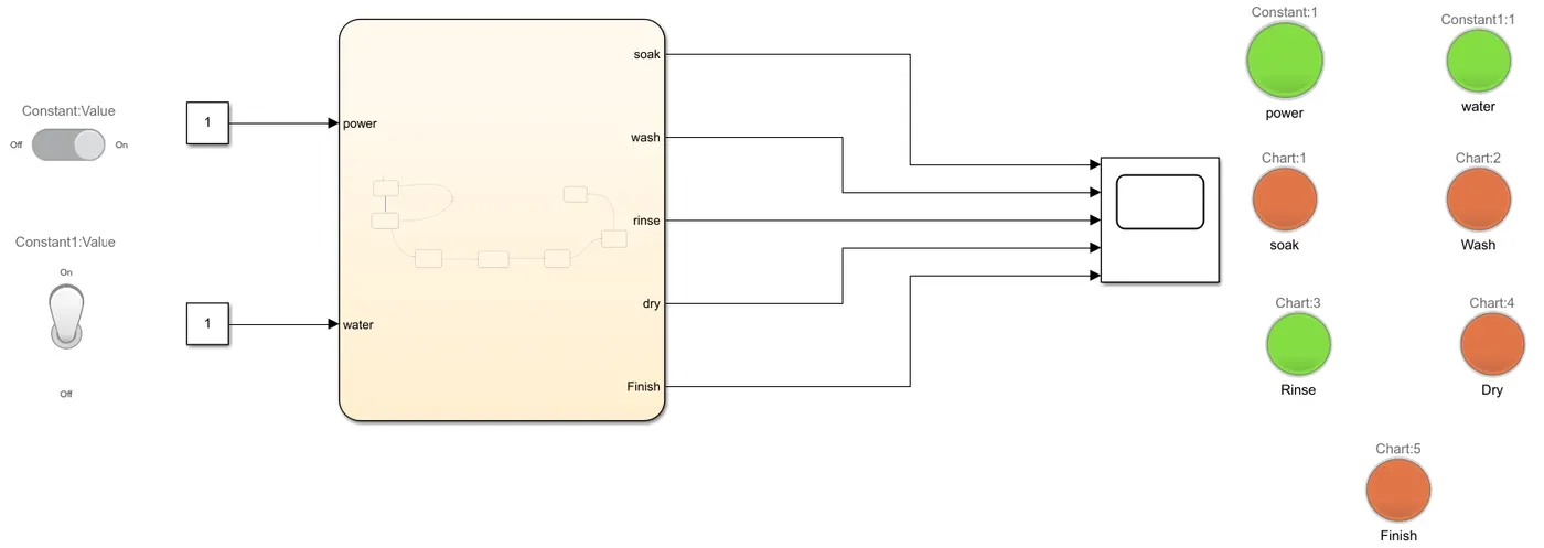
At t = 315 secs, Power :ON, Water:ON and the rinsing process is started.
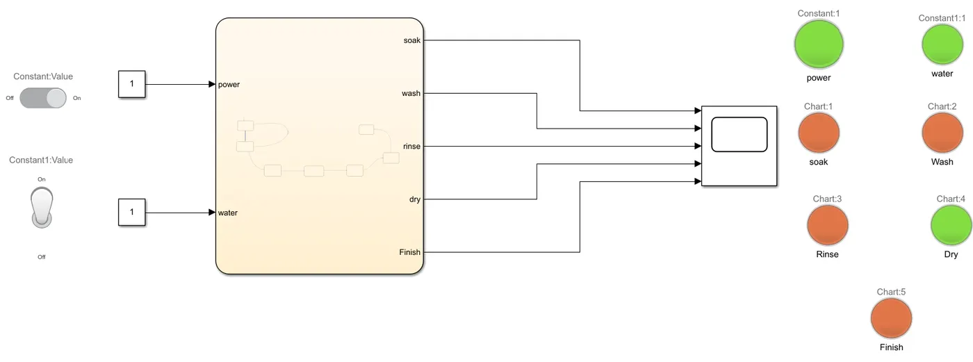
At t = 350 secs,Power :ON, Water:ON and the drying process is started.
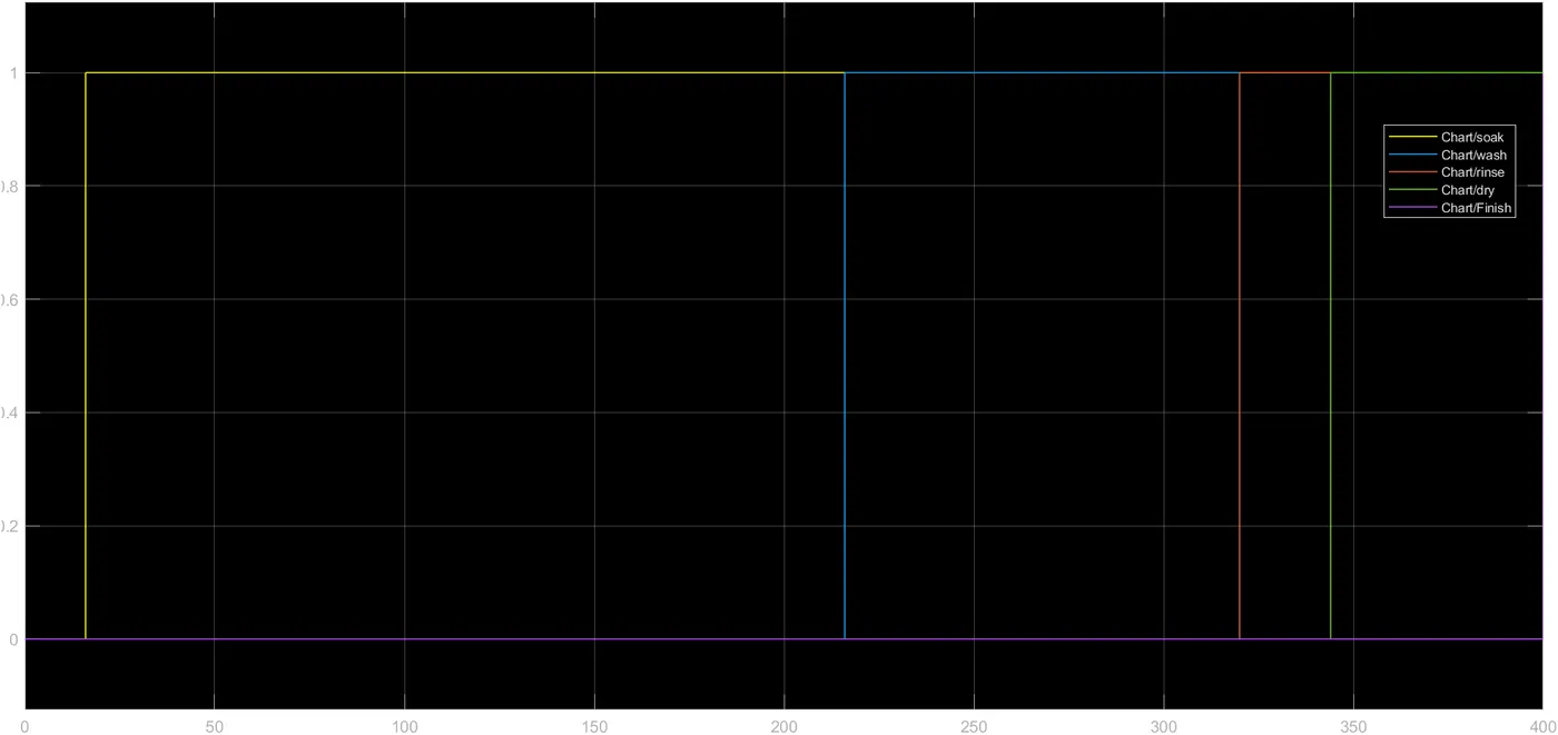
After 370 secs the washing machine will be stopped.At t = 400 secs, the finish button will be displayed.
After 370 secs washing machine will finish all the process and the below graph indicates that processes at t = 400 secs.
2. TO GENERATE A SIMULINK MODEL TO SHIFT THE GEAR ACCORDING TO GIVEN INPUTS
INTRODUCTION:
Transmission is a metal case that houses aseries of gears - which explains the nickname of gear box.
The transmission takes powers from the engine and delivers it to the wheels to help power our vehicle.It is responsible for making sure the right amount of power goes to the wheels so that it can operate at a given speed.
Types of transmission:
1.Automatic Transmission (AT)
2.Manual Transmission (MT)
3.Automated Manual Transmission (AM)
4.Continuously Variable Transmission (CVT)
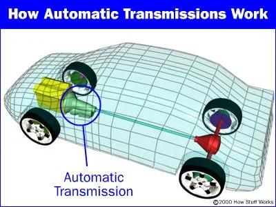
In this model we are simulating automatic gear shift w.r.t input speed.An automatic transmission, also called auto, self-shifting transmission, n-speed automatic (where n represents its number of forward gear ratios), or AT, is a type of motor vehicle transmission that automatically changes the gear ratio as thevehicle moves, meaning that the driver does not have to shift the gears manually.
Operations performed:
- 1st gear - (0-15 kmph)
- 2nd gear - (16-25 kmph)
- 3rd gear - (26-40 kmph)
- 4th gear - (41 - 60 kmph)
- 5th gear - (above 61 kmph)
SIMULINK MODEL:
STATEFLOW MODEL:

The input and output values for the chart are selected through symbols pane.
EXPLANATION:
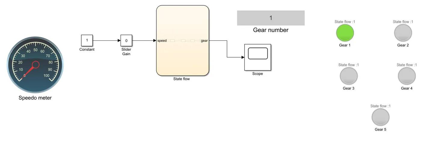
- Initially the slider value will be 0.
- When we change the slider value it will be given as input i.e., speed to the state flow where it checks the speed and displays the speed related gear number.
- In this simulink model the speed limit is taken as 100 kmph.Whenever we changes the slider input value the speed value will be displayed on speedometer.
- When the speed is between (0 - 15 kmph), then 1st gear will be activated.
- When the speed is between (15 - 25kmph) , then 2nd gear will be activated.
- When the speeed is between (26 - 40kmph), then 3rd gear will be activated.
- When the speed is between (41 - 60 kmph), then 4th gear will be activated.
- When the speed is between (above 61), then 5th gear will be activated.
- Whenever the speed increases or decreases the gear number will be displayed and the respected LED/ lamp will be blinked.
RESULTS:
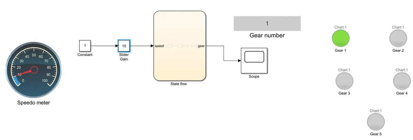
1st gear : The 1st gear is activated when speed is 10kmph .
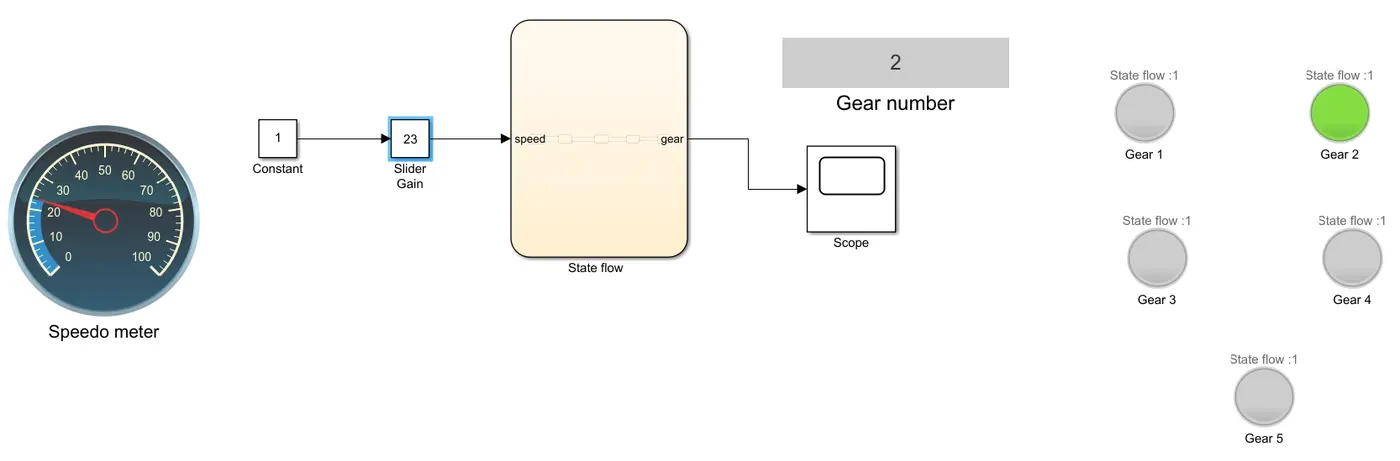
2nd gear : The 2nd gear is activated when speed is 23kmph.
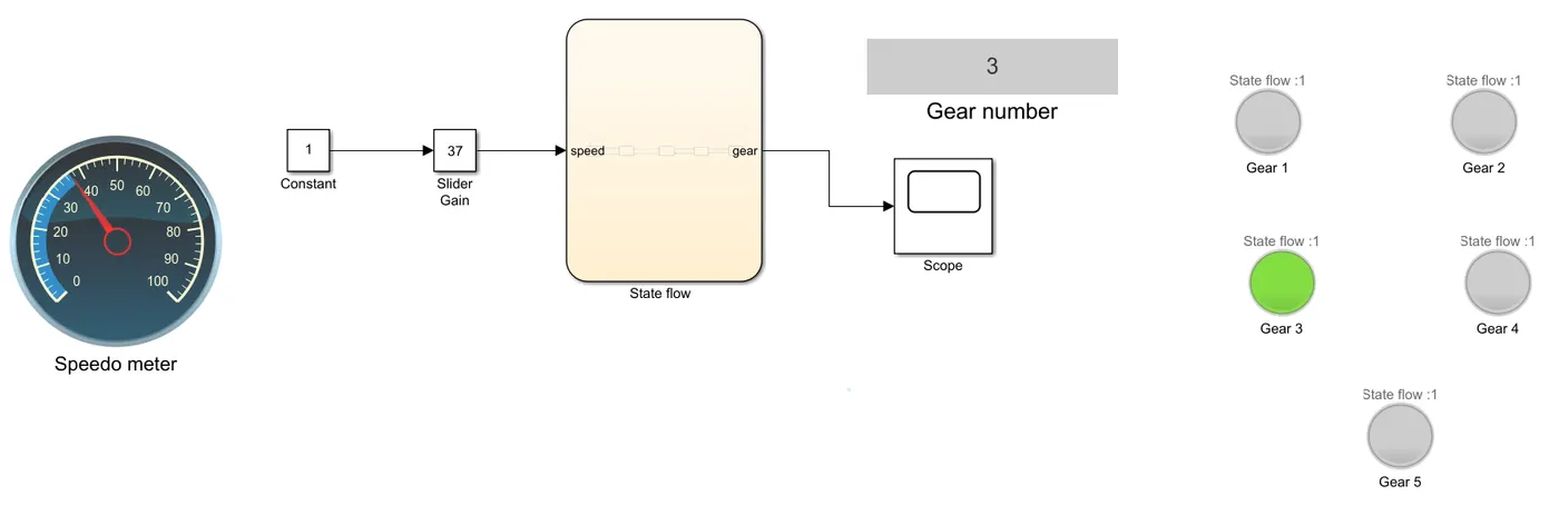
3rd gear : The 3rd gear is activated when speed is 37 kmph.
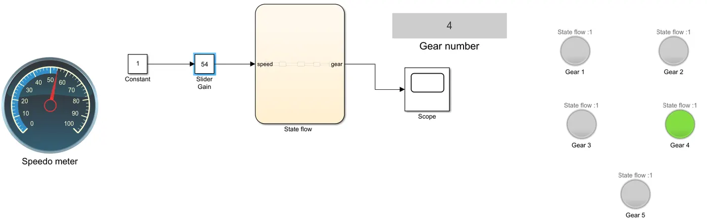
4th gear : The 4th gear is activated when speed is 54kmph.
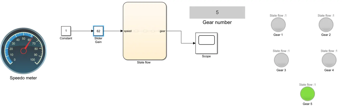
5th gear : The 5th gear is activated when speed given is 62kmph.
CONCLUSION:
The simulation of washing machine and gear transmission system is done and the output of the models are generated.