Simulation for doorbell using solenoid block and Use of a thermistor to switch ON and OFF the fan for a particular temperature
AIM:
1.To make a Simulink model of Doorbell using solenoid block .
2.To use a thermistor to sense the temperature of a heater & turn on or turn off the fan .
OBJECTIVE:
1.To create a situation where the switch is closed for 2 seconds and then released. Observe the physical movement of the plunger.
2. To sense the temperature of a heater by using some conditions.Temperature source: 20 °C from 0 to 10 seconds, 27 °C from 10 to 30 seconds, 23 °C from 30 to 50 seconds
Fan conditions: ON if the temperature above 25 °C, OFF otherwise
DESCRIPTION:
Doorbell:
The heart of a doorbell is a electromagnet.When you press a doorbell button , you complete an electric circuit that allows household electricity to flow through the doorbell's internal magnet.The magnetic field generated by the electromagnet is then used to power a mechanism that creates the doorbell sound.
SOLENOID :
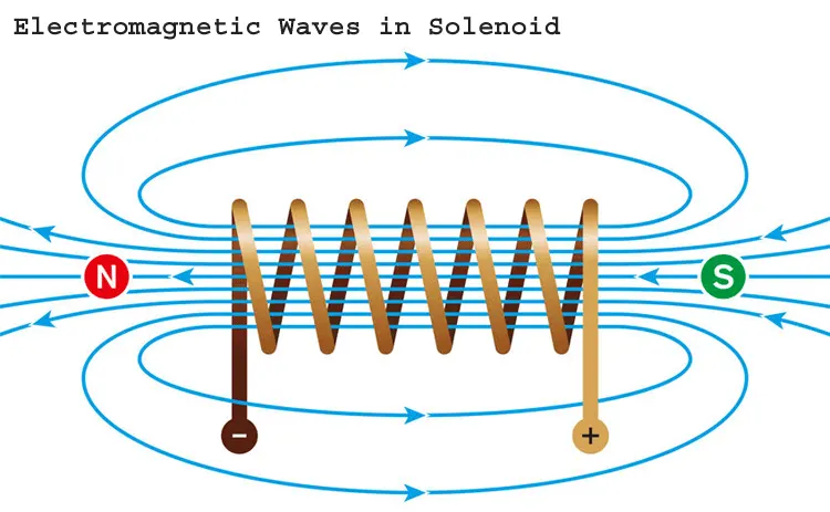
A solenoid is a device comprised of a coil of wire, the housing and a moveable plunger (armature). When an electrical current is introduced, a magnetic field forms around the coil which draws the plunger in. More simply, a solenoid converts electrical energy into mechanical work.
WORKING PRINCIPLE OF DOORBELL USING SOLENOID:
The switch is closed when the buzzer is pressed.This causes a current to flow through the circuit.
A magnetic field is now produced by the electromagnet.
The iron contact is now attracted towards the magnetic field.
When the contacter moves towards the magnetic field,the clapper now hits the bell.At the sametime this breaks the circuit.
Now there is no current flowing,so there is no magnetic field.The iron contact now springs back to its original position.
Now the circuit is complete again.So,a current flows around the circuit and the process is repeated.
SIMULINK MODEL :
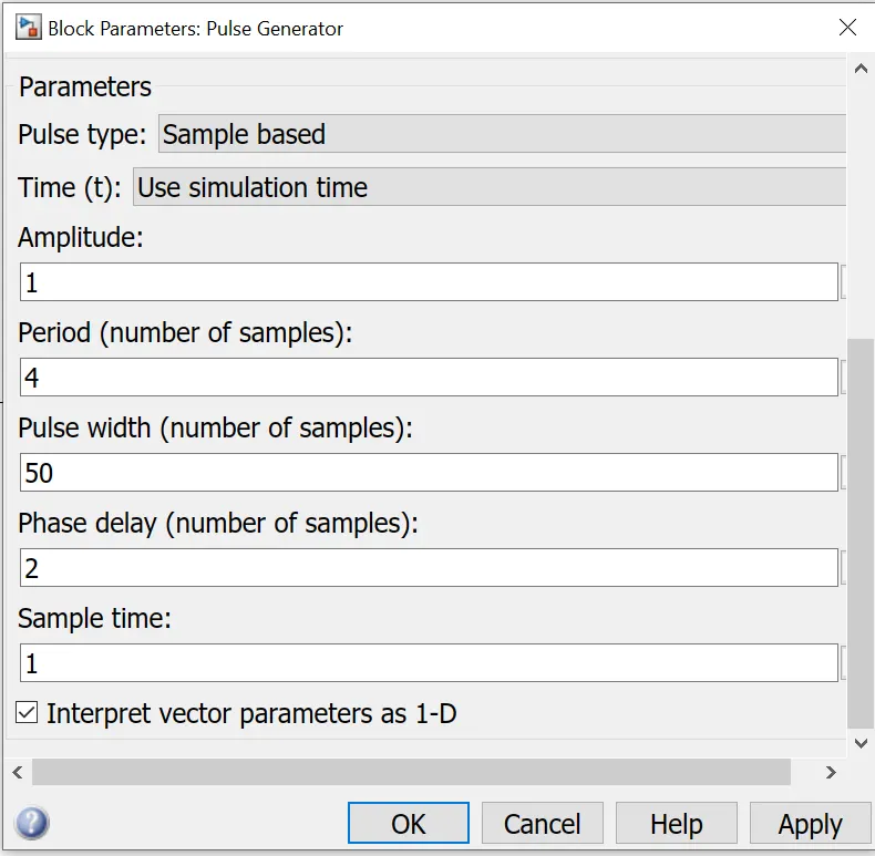
Pulse generator is given as an input signal with the following conditions:
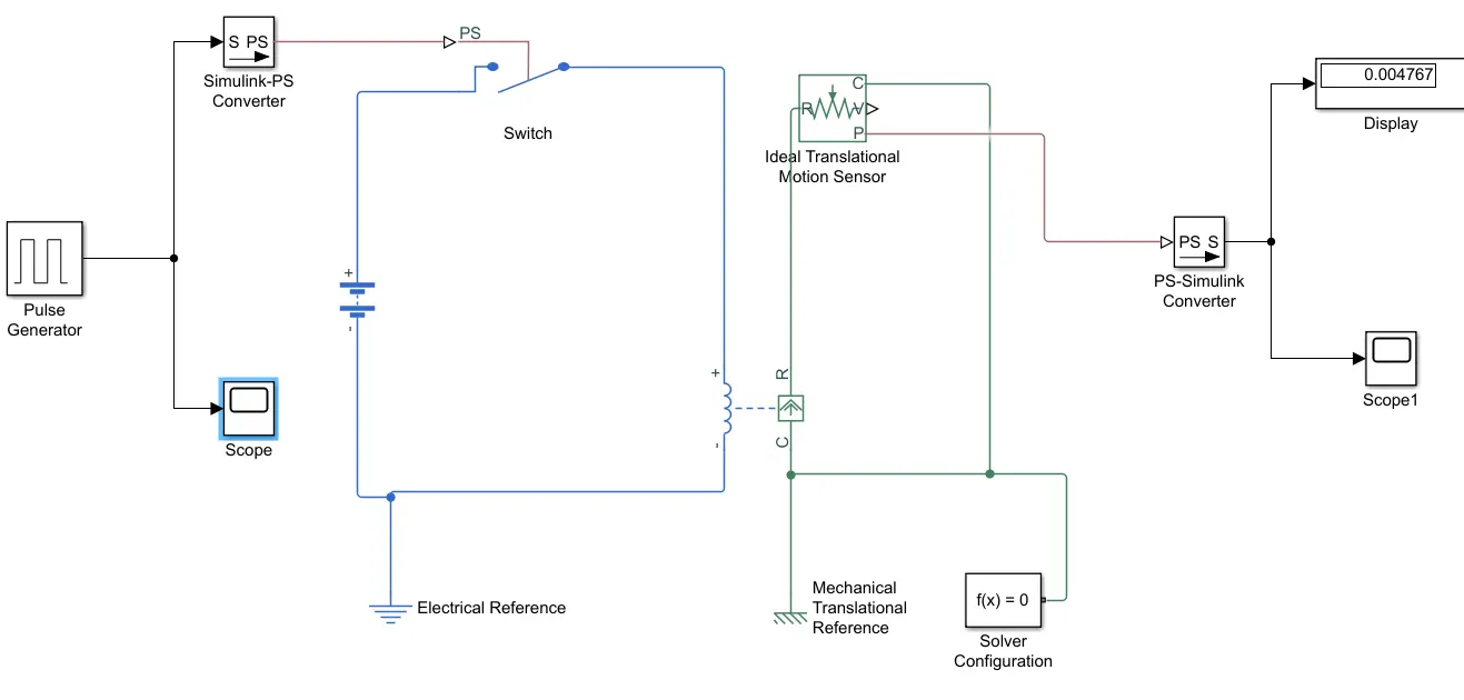
A simulink-PS converter is used to convert the input simulink signal into a physical signal.
A switch is connected to battery and solenoid respectively.If the external physical signal is greater than the threshold,then the switch is closed,otherwise switch will be open.
Solenoid converts electrical signals into mechanical signals.
An ideal translational motion sensor is connected with solenoid block to observe the physical movement of the plunger.
A PS-Simulink converter is used to convert the physical signal in to a simulink signal.
The solver configuration block specifies the solver parameters that your model needs before you can begin simulation.
Output of the model can be seen through scope.
RESULT :
PWM CONVERTER
Given input time period 4 seconds to open and close the switch.
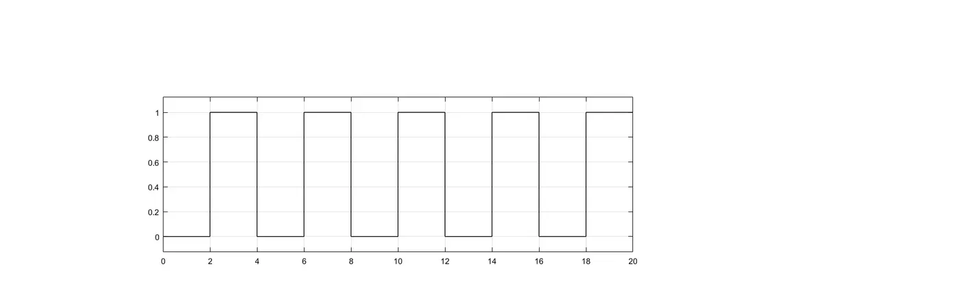
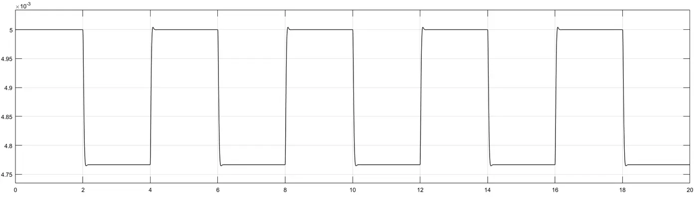
By reducing the spring constant value and increasing the damping value vibrations will be reduced.
THERMISTOR:
A thermistor is also known as thermal resistor.Is is defined as a type of resistor whose electrical resistance varies with changes in temperature.Although all resistors' resistance fluctuate slightly with temperature,a thermistor is particularly sensitive to temperature changes.
There are two types of thermistors :
1.Negative Temperature Coefficient (NTC).
2.Positive Temperature Coefficient(PTC).
Signal Builder:
In signal builder, the temperature input values are given as per the conditions :
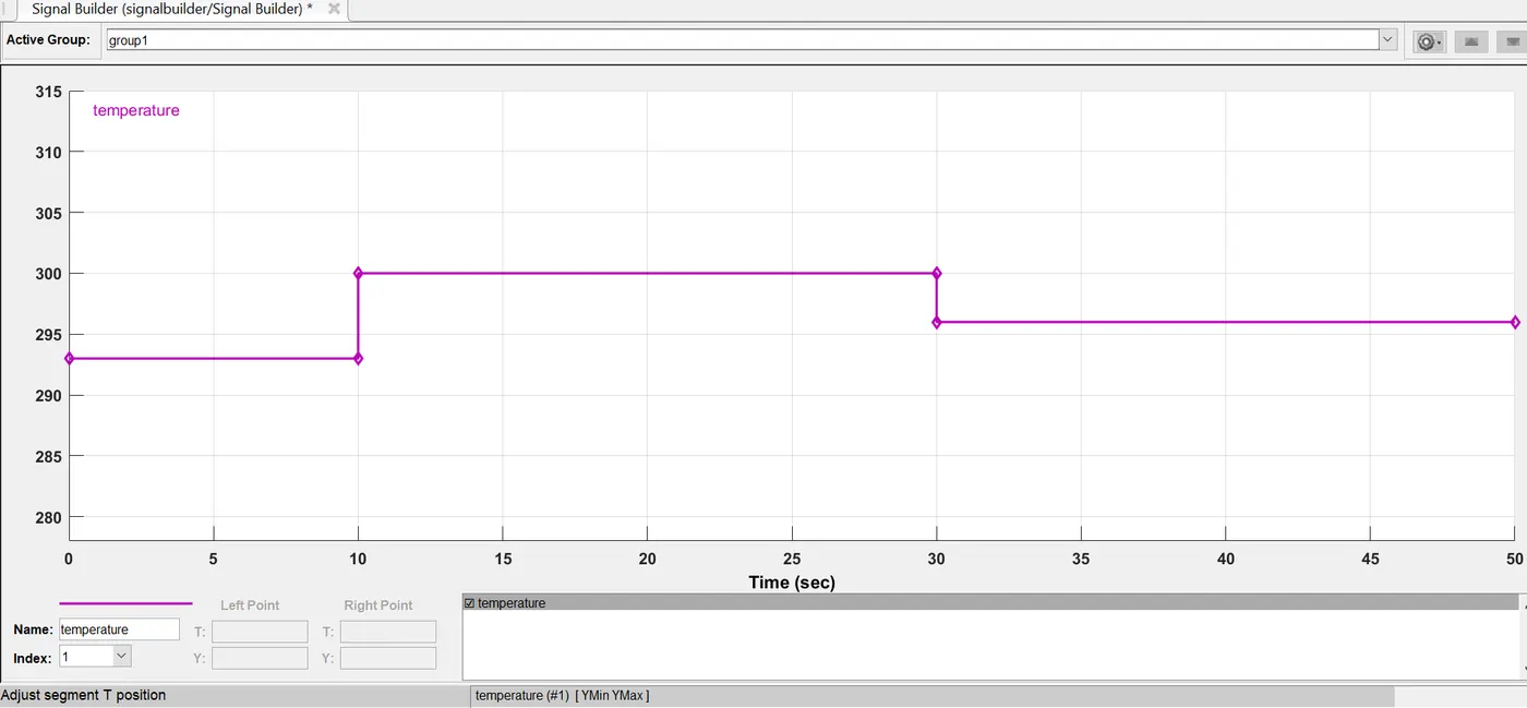
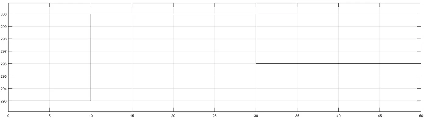
At point 1: Time 0 sec , Temperature 293K
At point 2: Time 10 sec , Temperature 293K
At point 3: Time 10 sec , Temperature 300K
At point 4 : Time 30sec, Temperature 300K
At point 5: Time 30sec, Temperature 296K
At point 6: Time 50sec , Temperature 296K
Controlled Temperature Source:
The controlled Temperature Source block represents an ideal source of thermal energy that is powerful enough to maintain specified temperature difference across the source regardless of the heat flow consumed by the system.
Voltage Sensor:
The voltage sensor block represents an ideal voltage sensor,that is a device that converts voltage measured between two points of an electrical circuit into a physical signal proportional to the voltage.
Electrical Reference :
The electrical reference block represents an electrical ground.A model with electrical elements must contain atleast one electrical reference block.
SIMULINK MODEL:
DESCRIPTION:
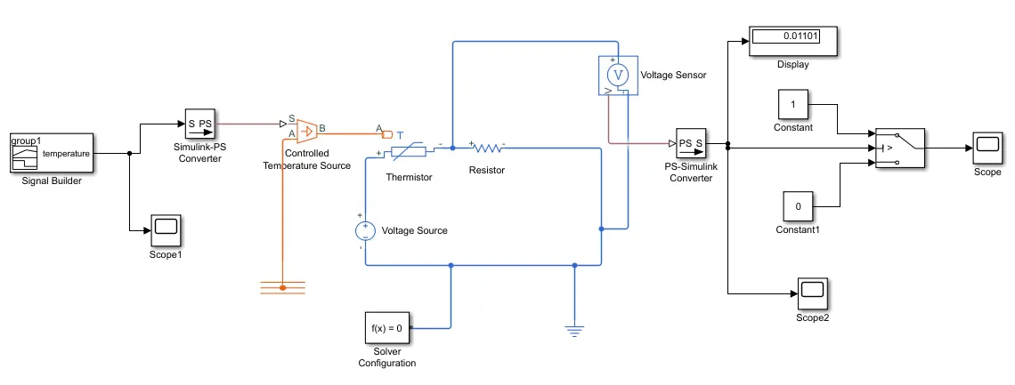
Inputs are given to the signal builder and it is connected to temperature controlled source through simulink-PS converter.
The Simulink-PS converter block converts the input simulink signal into a physical signal.
The temperature controlled source maintains the specified temperature difference across the source.Then input temperature flows through the resistor.
Thermistor is connected with the positive terminal of the resistor.Connect the positive terminal of the voltage source to positive terminal of the thermistor and negative terminal of the voltage source to negative terminal of the voltage sensor and the resistor.
The value of the voltage source should be 12V dc.
Output terminal of the voltage source is connected to switch.Using switch parameter for given condition the fan should be ON for temperature above 25 degrees otherwise fan should be OFF.
The obtained output can be using scope block.
RESULTS:
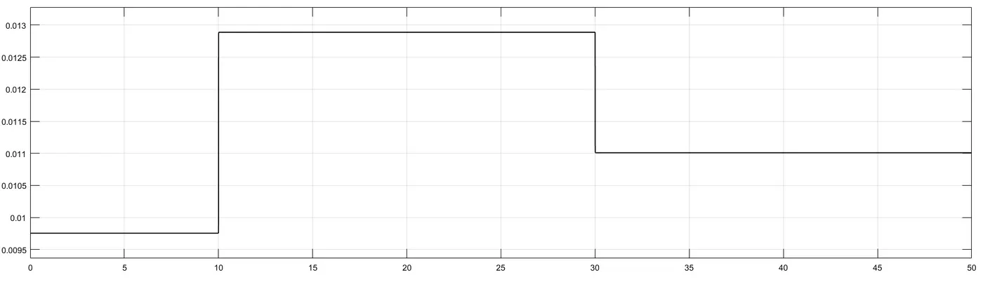
A plot for voltage sensor is displayed below:
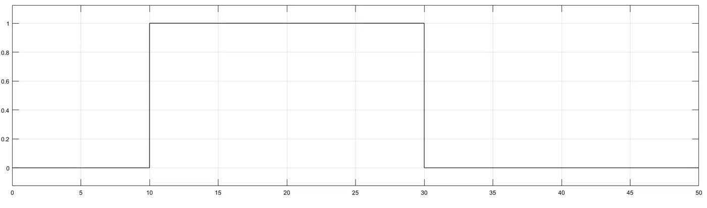
A plot is displayed below for: 293K for 0 to 10 secs, 300K from 10 to 30 secs and 296K for 30 to 50 secs.
The fan is ON for 20-30 sec as temperature is above 25°C and for one 10 secs and last 20 secs the fan is in OFF conditon.