Analysis of Buckling phenomena for Cyclone separator stand using solidworks
BUCKLING Analysis for Cyclone separator Stand
AIM :
To perform Buckling Analysis for a Cyclone separator Stand and optimization by design study for stiffener position.
OBJECTIVE :
- To perform a buckling analysis on a cyclonic separator stand.
- Create a metallic stiffener on the legs of the stand and perform the analysis to find out the change in buckling factor of safety.
- To run a design study and find the optimum position for the stiffener.
- Comparison of results for all the cases.
INTRODUCTION :
- The device that uses the principle of inertia to remove particulate matter from flue gases is known as Cyclone separator. A cyclone separator has several colloquial names. These names include ‘dust separator, dust collector, dust extractor, cyclone extractor and cyclone separator.
- Buckling is the sudden change in shape of a structural component under load such as the bowing of a column under compression or the wrinkling of a plate under shear.
THEORY :
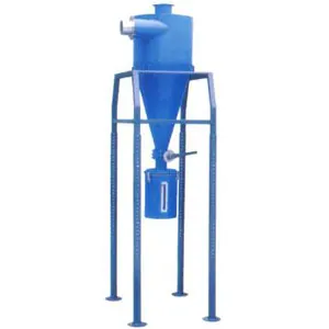
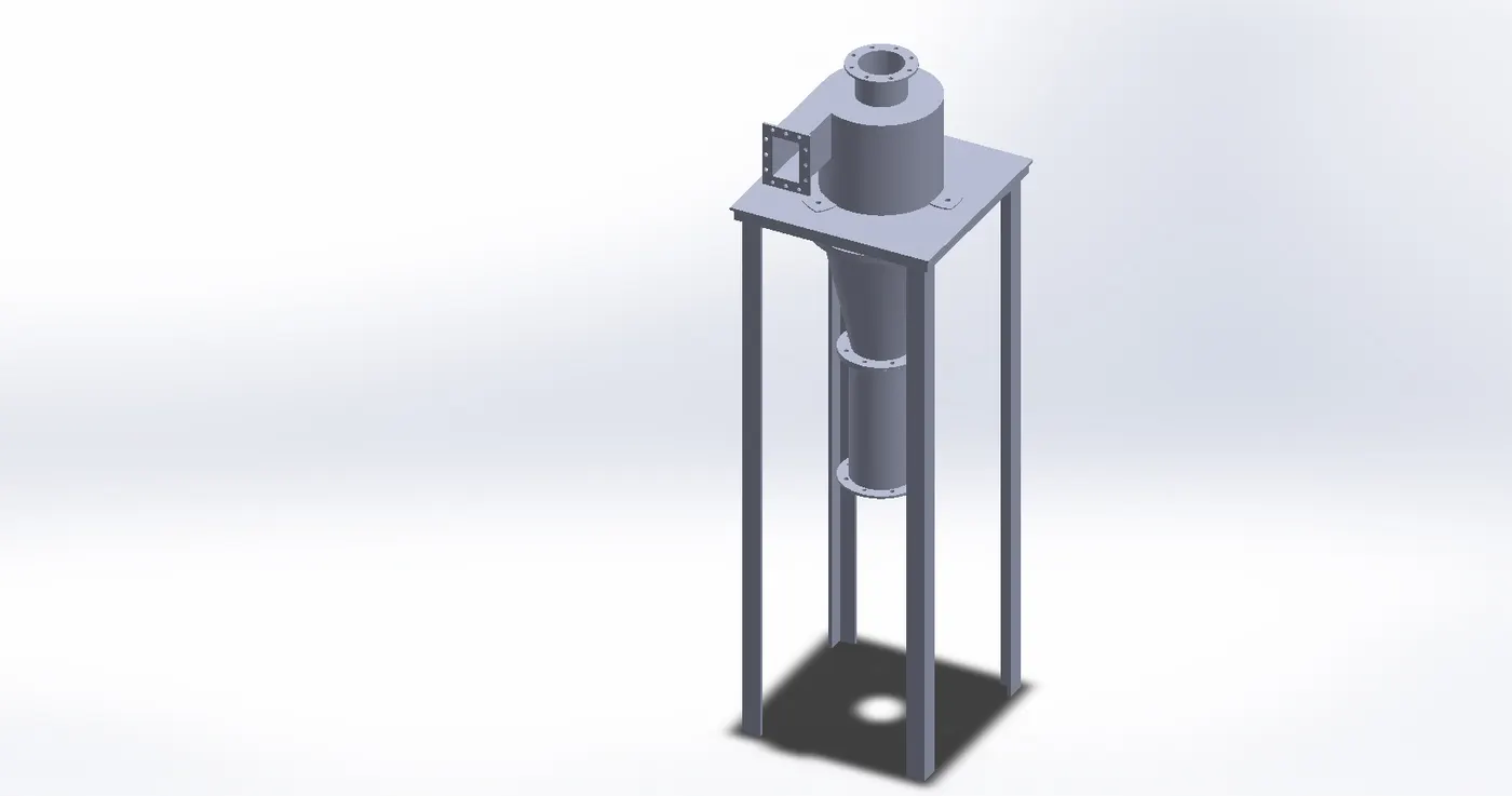
- Cyclone separators often form part of a pre-cleaning stage prior to a gas or liquid being discharged. This article focuses on the gas cyclone separator. Cyclonic separation is a means of separating different liquid phases (different liquid densities), or separating particles from a gas stream.
- If a structure is subjected to a gradually increasing load, when the load reaches a critical level, a member may suddenly change shape and the structure and component is said to have buckled.
- Buckling Analysis is an FEA routine that can solve all the difficult buckling problems that cannot be solved by hand calculations.
- Linear Buckling (LBA) is the most common Buckling Analysis.
- The nonlinear approach, on the other hand, offers more robust solutions than Linear Buckling.
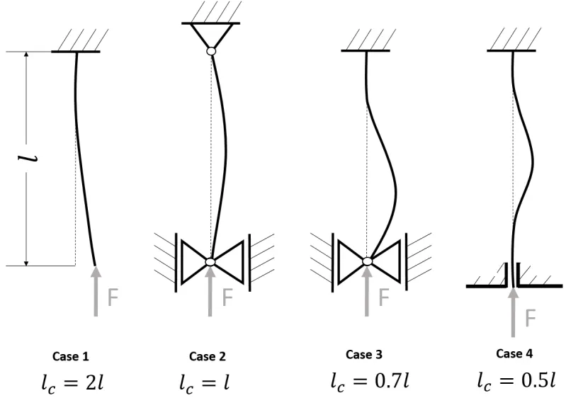
- Euler’ s Theory for long columns –
Euler’s analysis is based on following Assumptions –
- The material of the column is perfectly homogeneous and isotopic.
- The compressive load on the column is axial only.
- The column is free from initial stress.
- The weight of the column is neglected.
- The column is initially straight.
- The column fails only by buckling. This is true if the compressive stress in the column does not exceed the yield strength.
The 3 cases performed for this analysis are –
- CASE 1 For Cyclone separator Stand
- CASE 2 For Cyclone separator Stand with Stiffener
- CASE 3 Design Study for Cyclone separator Stand with Stiffener
CASE 1 Cyclone separator Stand
PROCEDURE :
- Import the step file of Cyclone separator and then remove the separator part by suppressing its all 3 parts and keep only separator stand for analysis.
- Select the simulation option in solidworks works environment to perform analysis and then go for a New study option.
- Choose the type of analysis to perform in our case select Buckling analysis.
- Apply the material for the parts of cyclone separator.
- Fix the geometry of the stand by using fixtures option on the part model.
- Apply the external load on the top face of the separator stand for force analysis.
- Create a Mesh for the whole stand part by using Mesh tools by choosing appropriate mesh parameters.
- Run the simulation and display the results for Buckling analysis as required.
CASE SETUP :
PART MODEL :
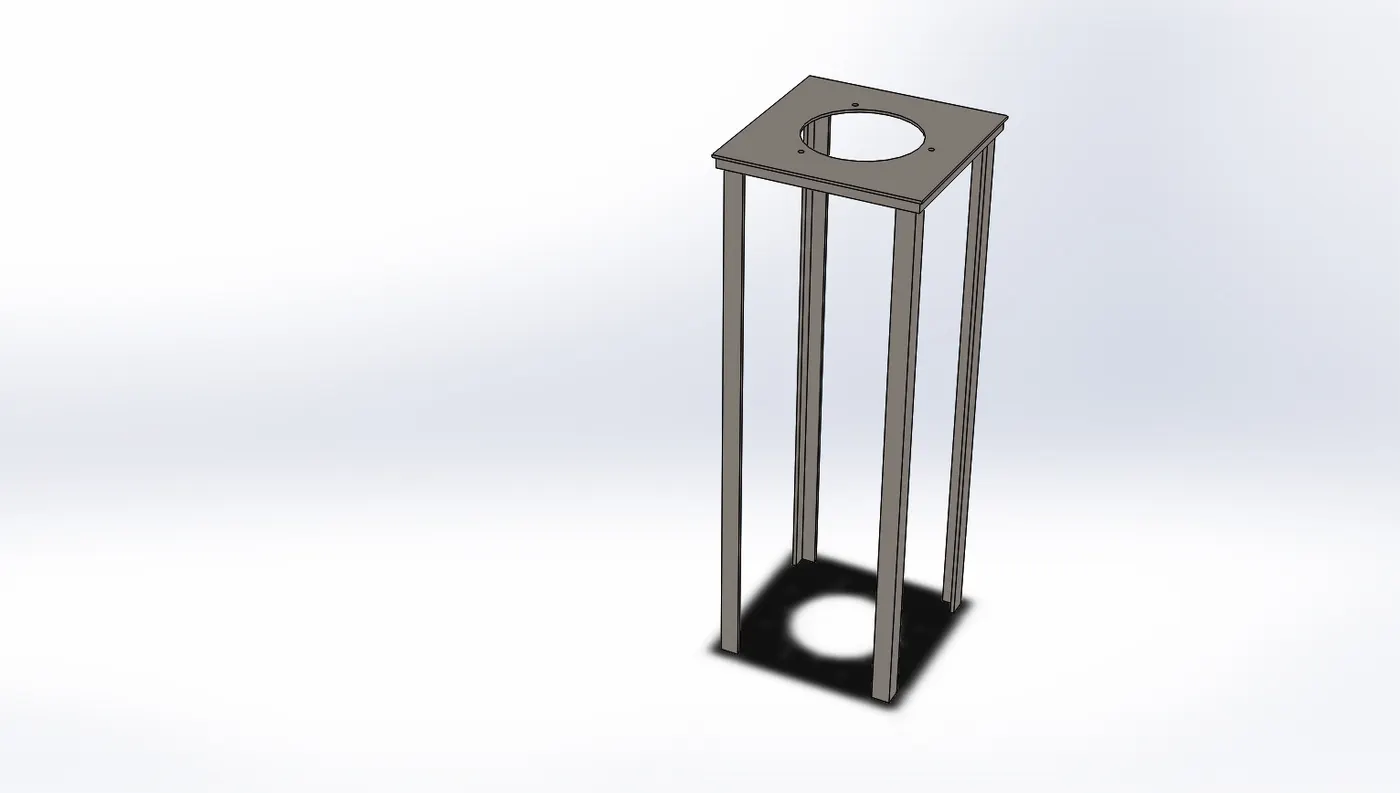
- For the part model use the file of cyclone separator stand and suppressed the other parts of separator except the stand and save it. The above image shows the model of the separator stand.
MATERIAL :
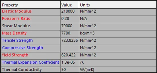
- The material applied for stand is Alloy steel. Alloy steel is having the yield strength 620.422 N/mm^2 and further properties are mentioned below.
MESH :
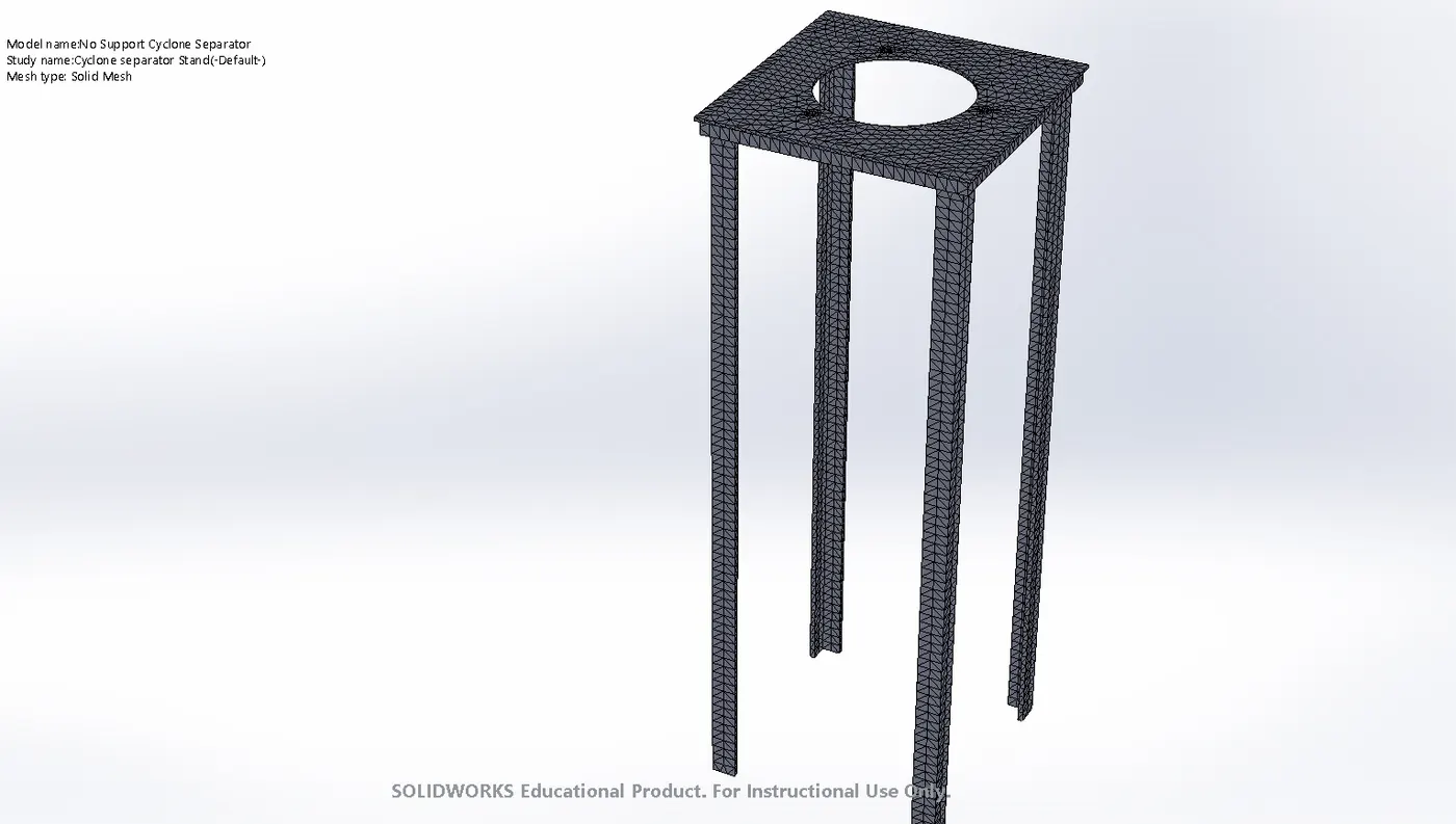
- In this stand model the mesh is generated using auto mesh tool by setting the parameter for fine mesh. After meshing, the element size developed is around 29 mm of solid mesh with high quality.
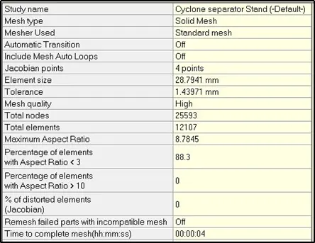
- The total nodes generated for mesh elements is 25593. The overall computational time took to complete this mesh for 12107 elements is 0.4 s.
FIXTURES :
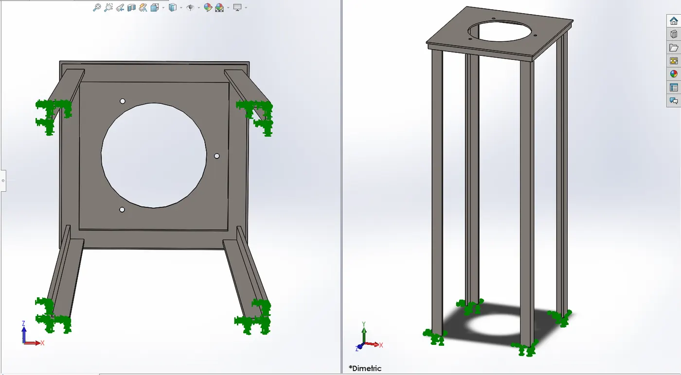
- The stand is fixed using fixed geometry from its bottom part to support it to withstand force applied on its top face. The fixtures are applied at the bottom face of the four legs of the stand model to strongly hold it for analysis.
LOAD :
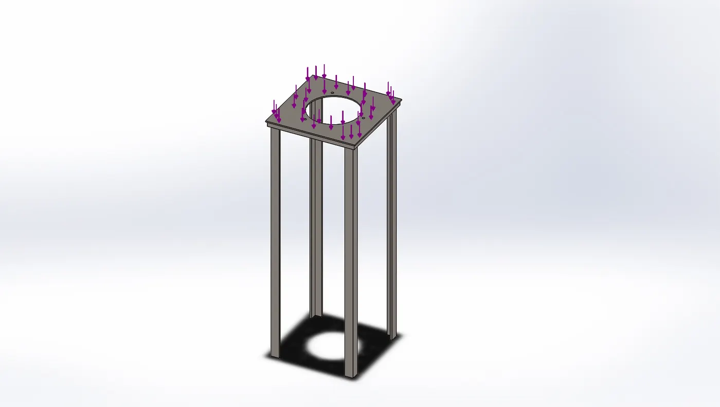
- The external load is applied on the top face of the stand. A force of 150 KN is set and applied on its top face for analysing the buckling effect.
RESULTS :
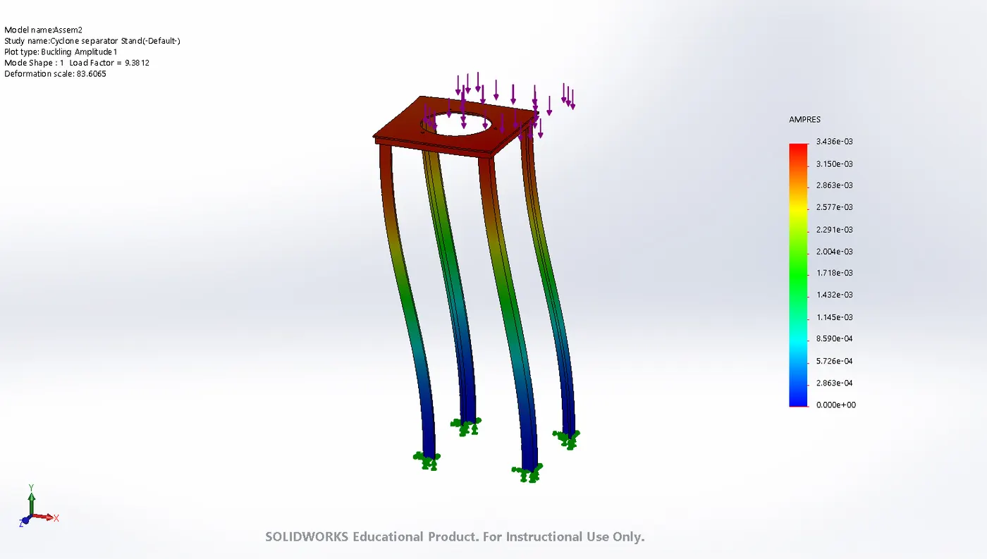
- The minimum value of amplitute is represented by blue color region in the base of stand in legs and in legends. And the maximum buckling amplitude value is at the top face of the stand indicated by red region and also in legend. So, after applying the load of 150 KN we get maximum value of 3.436e-03 as the buckling amplitude.

- For the cyclone separator stand after the analysis we got the Buckling Factor of safety as 9.3779 after applying the load of 150 KN on stand. Th Buckling FOS is almost 10 which means we need around 10 times the force applied on stand for failure. So, in our case the stand is safe under 150KN load.
CASE 2 - Cyclone separator Stand with Stiffener
PROCEDURE :
- Open the file of cyclone separator and then suppress the cyclone separator 3 parts and keep only separator stand for analysis.
- Save this file as a part file for the separator stand and then open it on a new page.
- Draw a sketch for stiffener on the stand, give thickness for extrusion and then offset it to a certain distance in the stand.
- Choose simulation in solidworks to perform analysis and then go for a New study option.
- Select the type of analysis to perform in our case go for Buckling analysis.
- Apply the material for the parts of cyclone separator.
- Apply the fixtures at a particular face of the stand to hold it while performing analysis.
- Apply the external load on the top face of the separator stand for force analysis.
- Create a Mesh for the whole stand part by using Mesh tools by choosing appropriate mesh parameters.
- Run the simulation and display the results for Buckling analysis and Buckling FOS .
CASE SETUP :
PART MODEL :
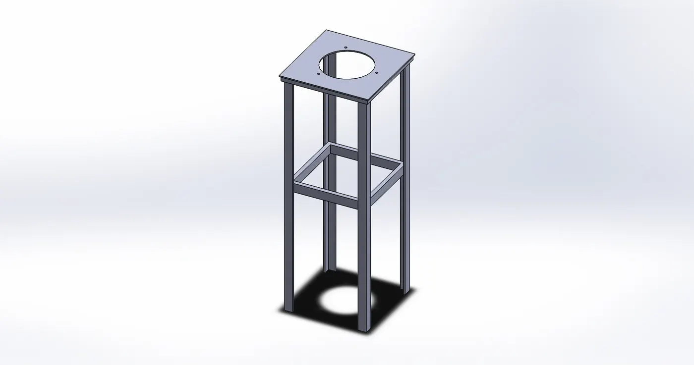
- For the part model use the file of cyclone separator stand and suppressed the other parts of separator except the stand and save it as a part file.
- To create a stiffener we had 1st drawn a 2D sketch using top plane of stand and then used features to convert it to 3D part as a stiffener by extruding it for 75mm. Also, a offset to stiffener is given from the top plate of stand at a distance of 1m which now indicates the position of the stiffener in the four columns of stand. The above image shows the model of the separator stand with a stiffener.
MATERIAL :
- The material applied for stand is Alloy steel. Alloy steel is having the yield strength 620.422 N/mm^2 and further properties are mentioned below.
MESH :
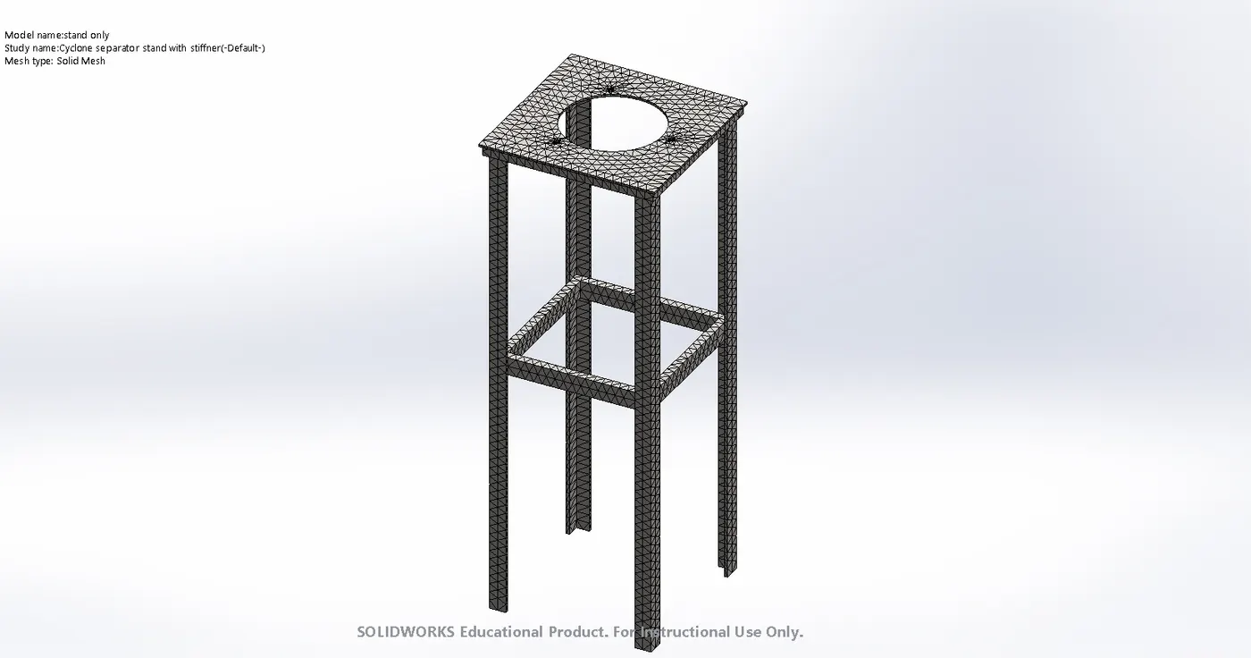
- In this stand with stiffener model the mesh is generated using auto mesh tool by setting the parameter for fine mesh. After meshing, the element size developed is around 37 mm of solid mesh with high quality.
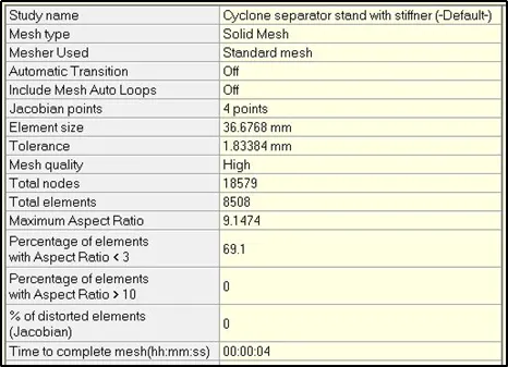
- The total nodes generated for mesh elements is 18579. The overall computational time took to complete this mesh is 0.4 s for 8508 total elements.
FIXTURES :
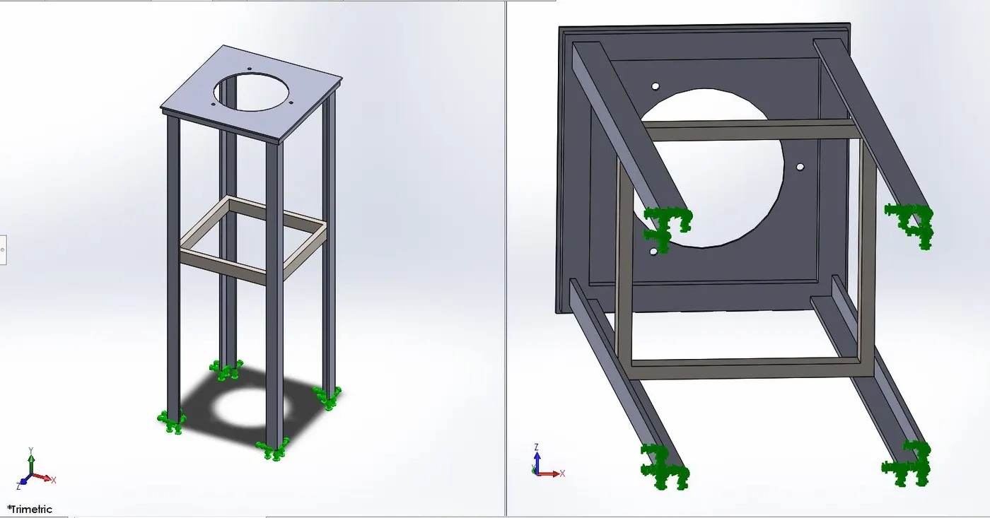
- The fixed geometry is used fix the stand from its bottom part to support it to withstand force applied on its top face. The fixtures are applied at the bottom face of the four legs of the stand model to strongly hold it for analysis.
LOAD :
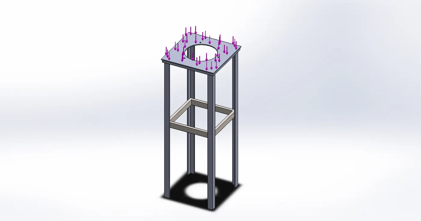
- The external load is applied on the top face of the stand. A force of 150 KN is set and applied on its top face for analysing the buckling effect.
RESULTS :
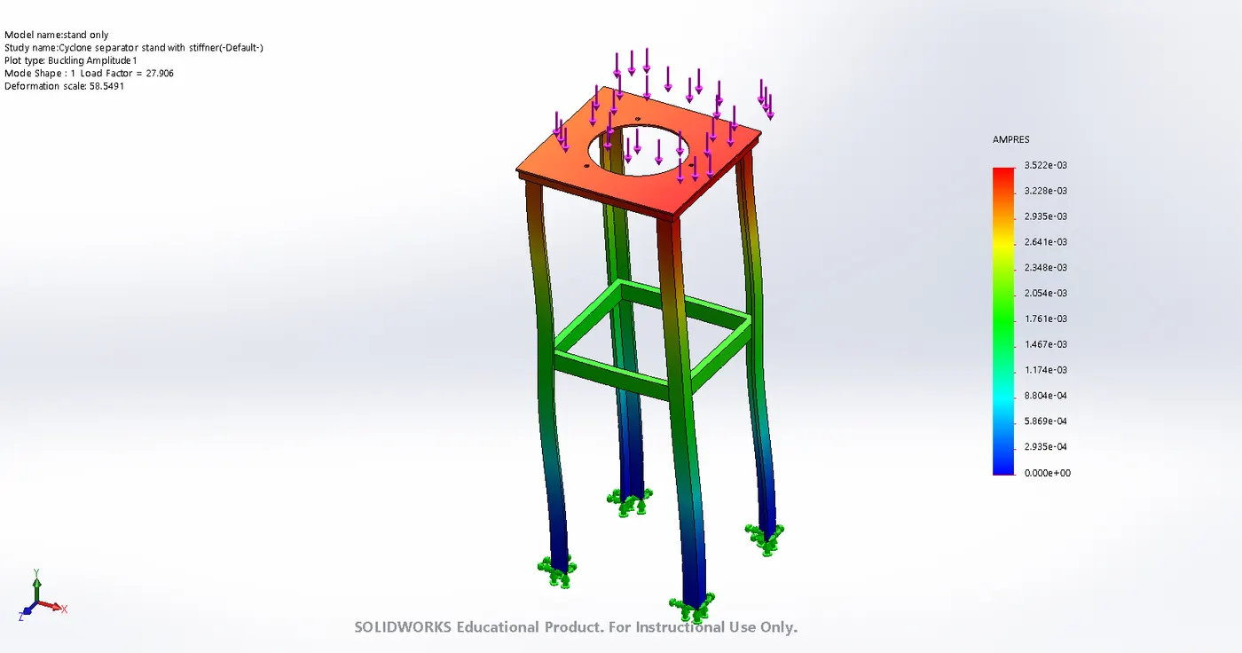
- Here, the minimum value of buckling amplitute is represented by blue color region in the legs of stand at base and also in legends. And the maximum amplitude value is at the top face of the stand indicated by red region and also in legend. So, after applying the load of 150 KN we get maximum value of 3.552e-03 as the buckling amplitude.

- For the cyclone separator stand with stiffener after the analysis we got the Buckling Factor of safety as 27.906 after applying the load of 150 KN on stand. Th Buckling FOS is almost 30 which means for failure of stand we need around 30 times the force applied. So, in our case the stand with stiffener is safe under 150KN load with high Buckling FOS.
CASE 3 Design Study for Cyclone separator Stand with Stiffener
PROCEDURE :
- Import the cyclone serparator file and follow the same procedure done in Case 2 to create stand part with stiffener.
- For performing buckling analysis and its setup perform the steps of Case 2 similarly.
- Now, after getting the results of Buckling FOS and its plots go for a New study in simulation.
- Choose the design study option and set the various parameters in variable view box.
- For optimization setup 1st set the variables by adding the a parameter for position of stiffener with limits.
- Then apply the constraints for Buckling FOS for cyclone separator stand with stiffener.
- Then set the goals in Variable view in other words objective function for the stand model respectively.
- Finally, run the study for optimization and get the design results.
CASE SETUP FOR DESIGN STUDY :
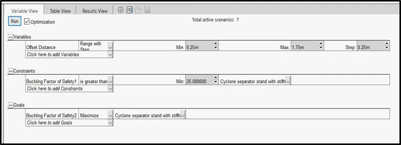
- For the design study we need to set the various parameters to study and its bounds. The above image shows the Variable view setup to run optimization in design for cyclone separator stand with stiffener.
- First we had set the variables next the Constraints and then Goals. To set the variables we had choose Add parameters and then selected the dimension length of the stand with stiffener. Then named it as a Offset distance which determines the position of the stiffener.
- The min. value for offset distance we had given is 0.25m and max. value 1.75m with the step size of 0.25m for design study.
- Then, for constraints we selected Add sensors and then sensor type as Simulation Data then choose Buckling FOS a Data quantity. And set it as greater than with minimum value 25 for stand.
- The last parameter we set is the Goals in which we add the Buckling FOS quantity to maximize for the cyclone separator stand with stiffener.
RESULTS :

- The above image shows us the output results for design study in the results view dialog box. For this study the position of the stiffener varies from a offset distance from min. 0.25 to max. 1.75m as set in variables. The constraints are given for buckling FOS as greater than min. value 25 for analysis. The ultimate goal was to maximize the Buckling FOS so we had maximize it in goals section for this study.
- For this design study we simulation has run for 9 scenarios for different position of the stiffener. The optimum value we got from this study is at scenario 3 shown in results view. So, at a distance of 1m for stiffener position from the top of stand we got our optimum value for Buckling FOS which is 27.9 around 30 .
OBSERVATION :
|
Analysis |
Amplitude |
Buckling FOS |
|
|
Minimum |
Maximum |
||
|
Stand without stiffener |
0 |
3.436e-03 |
9.3779 |
|
Stand with stiffener |
0 |
3.552e-03 |
27.906 |
- The minimum value of buckling amplitude for case 1 and case 2 is same i.e. 0 and the maximum value for Case 1 stand without stiffener and maximum value for Case 2 stand with stiffener has a sight difference.
COMPARISON OF ALL RESULTS :
- For case 1 stand without stiffener we got the maximum amplitute value as 3.436e-03, whereas maximum value for Case 2 stand with stiffener is 3.552e-03.
- The Buckling FOS for Case 1 we got is almost 10 and for case 2 is almost 30. Here, for the same load of 150 KN the Buckling FOS increases in Case 2 in which we added the stiffener in the 4 coloumns of stand. This clarify that adding stiffener to support at base for 4 legs increases the strength of the stand to withstand the load.
- Thus, in case 2 we got more Buckling FOS than case 1. Case 2 had a stiffener at a positon of 1m from the top of the stand. In case 3 we had done the design optimization for the various position of the stand to get the maximum FOS. So, here in case 3 we got the Buckling FOS as 27.906 almost 30 at 1m position of the stiffener in stand.
- In case 1 the stand will fail after applying 10 times the force of 150 KN and in case 2 & case 3 the stand will after applying 30 times the load of 150 KN. So, case 2 is more safer and recommended.
CONCLUSION :
- A brief study for Buckling analysis had been done with valid results for the cyclone separator stand. The stand without stiffener has less Buckling FOS than stand with stiffener. It concludes that the stiffener strengthens the stand to withstand heavy load to prevent the failure with more safety. Also, design study has been completed and analyzed the results that is for 1 m offset of stiffener position we get maximum Buckling FOS for a cyclone separator stand. Hence, we understood the fundamentals for Buckling analysis and optimization for cyclone separator stand with stiffener by Design study in Solidworks.
REFERENCES :