MBD simulation for Planetary Gear
AIM :
To create 3D models, assembly and perform motion analysis on planetary gear.
INTRODUCTION :
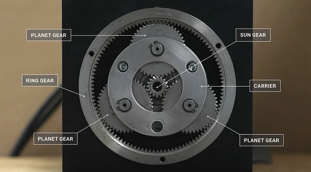
- A planetary gearbox is a gearbox with the input shaft and the output shaft aligned. A planetary gearbox is used to transfer the largest torque in the most compact form. Planetary gear train consists of two gears mounted so that the center of one gear revolves around the center of the other. A carrier connects the centers of the two gears and rotates to carry one gear, called the planet gear or planet pinion, around the other, called the sun gear or sun wheel. The planet and sun gears mesh so that their pitch circles roll without slip. A point on the pitch circle of the planet gear traces an epicycloid curve. In this simplified case, the sun gear is fixed and the planetary gearroll around the sun gear.
THEORY :
- Planetary gears are often used when space and weight are an issue, but a large amount of speed reduction and torque are needed. This requirement applies to a variety of industries, including tractors and construction equipment where a large amount of torque is needed to drive the wheels.
- Other places we can find planetary gear sets include turbine engines, automatic transmissions, and even electric screwdrivers.
- It is possible to realise different speeds and turning directions with the same construction. This can be achieved by, for example reversing the gearbox, which offers the following possibilities shown in below table:
- Planetary gear systems are able to produce a lot of torque because the load is shared among multiple planet gears. This arrangement also creates more contact surfaces and a larger contact area between the gears than a traditional parallel axis gear system. Because of this, in the load is more evenly distributed and therefore the gears are more resistant to damage.
- Formula used for calculation of parameters of gears is of module.
- Module = Pitch circle diameter / No. of teeth.
- M= pcd / n
For Ring Gear
- Module = 2.5 mm
- Number of teeth = 46
- PCD = 115 mm (Calculated by using module formula)
For Sun Gear
- Number of teeth = 14
- Module = 2.5 mm
- PCD = 35 mm (Calculated by using module formula)
- Input Speed of the Gear = 200 rpm.
For Planetary gears
- Module = 2.5 mm
- PCD = 40 mm (Calculated by using formula)
- Number of teeth = 16 (Calculated by using module formula)
- Number of planet gears = 4
PROCEDURE :
- Create the Sun gear, 4 planetary gears , ring gear with certain dimensions using design library in solidworks and save all the parts separately.
- Create a 2D sketch of Carrier which should match the requirements of 4 planetary gear shaft and then convert it into 3D using features in solidworks.
- Assemble all the gears and carrier one by one using various constraints and mates.
- Perform motion analysis for 3 cases in first case we fix ring gear, then 2nd sun gear and 3rd
- Obtain all the plots after running the analysis for gear motion.
SETUP :
3D MODEL :
- The above image shows us the modelled Ring gear with 46 teeth and 115 mm pitch circle diameter after calculation using 2.5 mm module.
- The above image shows us the sun gear with 14 teeth and 35 mm pitch circle diameter after calculation using 2.5 mm module.
- The above image shows us the 4 planetary gear with 16 teeth and 40 mm pitch circle diameter after calculation using 2.5 mm module.
- The above image shows the carrier part modelled depending on the shaft diameter of the planet gear.
ASSEMBLY :
- The above images represents the assembly for the planetary gear with carrier.
RESULTS :
- In case 1 input is sun gear, output we get for carrier rotating and the ring gear is fixed. The above plots indicates the change in angular velocity with respect to time for case 1.
- In case 2 input is ring gear, output we get for carrier and the sun gear is fixed.The above plots indicates the change in angular velocity with respect to time for case 2.
- In case 3 input is sun gear, output we get for ring gear and the carrier is fixed.The above plots indicates the change in angular velocity with respect to time for case 3.
CONCLUSION :
Hence, we had briefly understood the motion analysis of the planetary gear by performing analysis for all the 3 cases one by one respectively. Also, we had obtained and plotted the results for angular velocity of respective gear for analysis.
REFERENCES :