Section Modulus calculation and optimization
Section Modulus calculation and optimisation
Objective: To calculate the section modulus of the car hood previously designed by finding the Moment of Inertia using the NX CAD software, and also to optimise the cross section for a better result.
Introduction: Section Modulus is a geometric property used in design of flexural members which considers the cross section of the member. It is highly dependant of the shape of the cross section as well as the area of the said section. There are 2 types of section modulus:
1) Elastic Section Modulus: This is used when the yeild point of the material is considered as the acceptable limit. This is the most commonly used standard whenever a component is designed.
2) Plastic Section Modulus: In this case the elastic yeilding is deemed acceptable and plastic deformation is considered as the limit.
The Elastic Section Modulus is defined as S = I/y, where;
I = area moment of inertia
y = distance from the neutral axis to any given fibre
Neutral axis is the fibre in any given solid where longitudinal stresses and strains are absent.
Usually for calculating the Section Modulus, the most extreme fibre which is the farthest from the neutral axis is considered during the calculations.
The significance of Section Modulus is that it defines the resistance of a body to bending. Higher the value of Section Modulus, the more resistant is the body towards bending.
The procedure for calculating the Section Modulus is as follows:
Case 1: Original cross section of the hood.
Using the Intersection Curve command, the cross section of the hood is obtained.
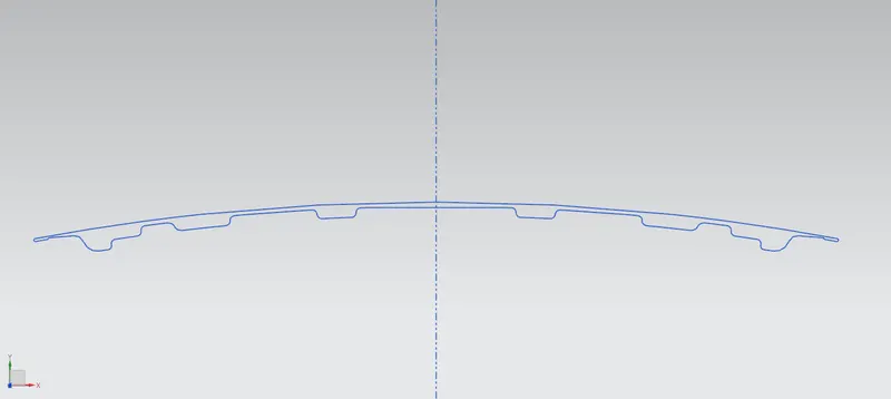
Now, to obtain the value of 'y', the distance from the neutral axis (construction line) and the extreme edge of the hood is measured.
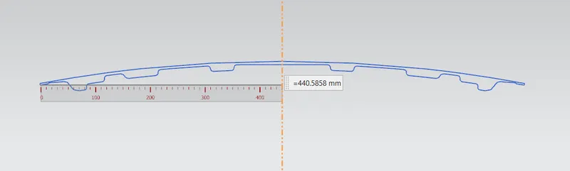
In this case, the distance is approximated to 440 mm.
The calculation for finding the area is made using the Section Inertia Analysis within NX CAD. The result of the software is given below.
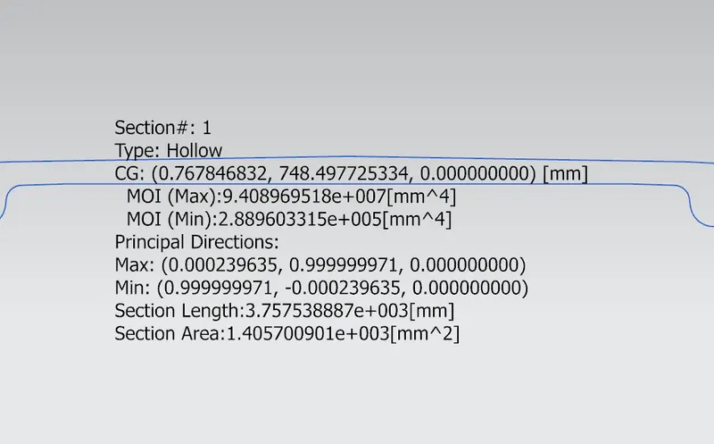
From the data above:
`I_max`= 94089695 `mm^4`
`I_min` = 288960 `mm^4`
Using the formula S = I/y,
`S_max`= 94089695/440 = 213840.2 `mm^3`
`S_min`= 288960/440 = 656.73 `mm^3`
Case 2: Modified hood cross section.
The original cross section curve is modified by offsetting the lower half of the cross section loop 1mm downwards. This simulates the increase of the depth of emboss within the drawing operation by 1mm.
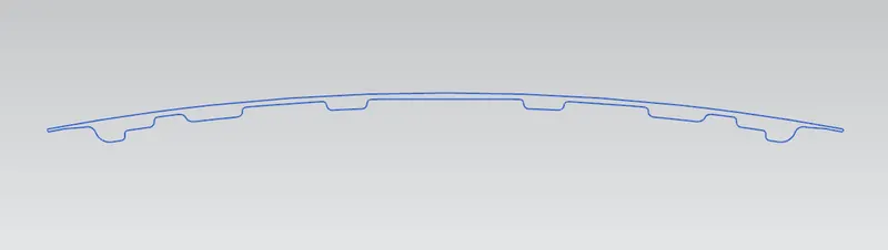
Running the command on the modified cross section, the results obtained are as follows:
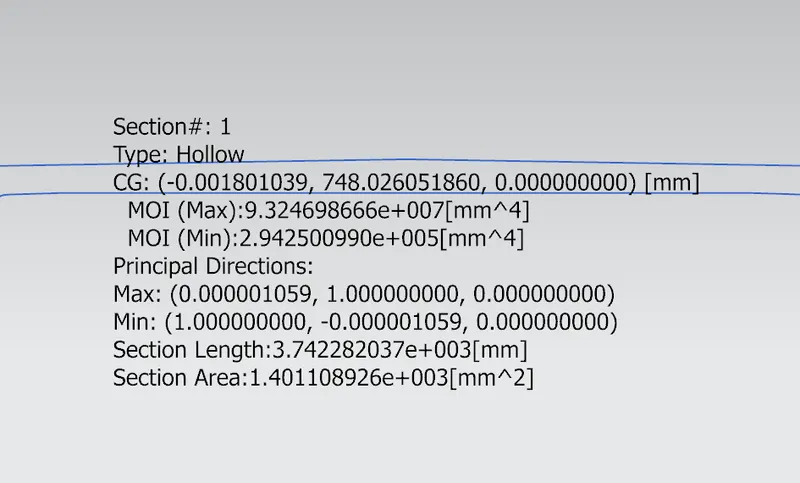
Calculating the maximum and minimum section modulus:
`S_max`= 93246986/440 = 211925 `mm^3`
`S_min`= 294250/440 = 668.75 `mm^3`
Comparing the minimum Section Modulus values obtained for both cases, it can be deduced that the modified hood gives a greater result. The reason for going with the minimum values is that during designing, the minimum value is given priority if the product is to be made with safety in mind. So manufacturers try to maximise the minimum Section Modulus via optimization.
Conclusion:
1) The increase in Minimum Section Modulus is 1.83%.
2) Section Modulus increases with increase in cross section area.
3) Section Modulus can be increased by incresing the gap between the outer and inner panels.