Roof Design
Roof Design
Introduction:
The automobile roof is one of the most crucial components present in any modern-day automobile. Throughout the years, the design of the roof has kept on improving: from the inclusion of aerodynamics to the provision of accessories such as sunroofs. Roofs nowadays for most automobiles are made not only for protection against the elements but to also protect the passenger in case of accidents. The design of the roof also brings into consideration the weight reduction resulting from fuel efficiency goals.
The goal of the project is to create reinforcements from given skin data obtained from the styling team considering the heat distortion and snow load criteria.
Design process:
The design of the roof components and assembly was performed as follows:
1) Roof outer panel
The outer panel of the roof is the initial roof panel modeled by the styling department. This surface is to be evaluated for the aforementioned heat distortion and snow load criteria, along with being used as a reference surface for the reinforcements to be modeled. Initially, a new surface is extracted from the skin data, which will now be used as the new reference. Flanges are provided for the new surface to simulate the assembly points for the front windshield, side doors, and back door.
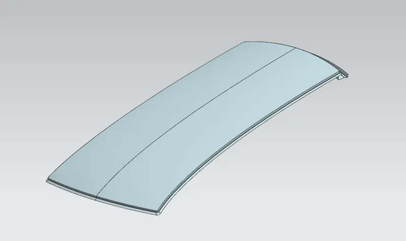
2) Front roof rail:
The front roof rail is a component that provides support to the front end of the roof. It also acts as an anchor or support for the front windshield. This rail is designed keeping into consideration the driver's height and the depth of the cosmetic headliner for the interior. For this case, the separation for all inner and outer panels is kept at 5 mm unless specified. The front flange of the rail touches the roof's outer panel since this joint will be spot welded. Welding is done for locations where the outer panel is not visible to the naked eye, which preserves the vehicle's aesthetics.
The modeling itself involves operations such as offsetting the roof's outer panel surface at required distances from the roof panel and trimming them accordingly. Law extensions are provided in such a manner that the draft relief of 7 degrees is implemented. Necessary face and edge blends are given as well. Optional gussets for sheet metal strengthening are also given. The final thickness of the rail is assigned at 0.75 mm, the same for every other panel.
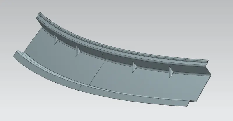
3) Centre roof rail:
The center roof rail is a type of reinforcement given to the roof. As the name suggests, the center roof rail is positioned almost exactly in the center along the longitudinal axis of the roof. Irrespective of the curvature or length of the roof, the center roof rail is always present. For snow loading, the center roof is usually the primary component that resists the dead weight of the snow, because of which it is usually wider than any other inner roof rails. In special cases, sunroof accommodations are also provided by adding a supplementary roof rail t the existing center rail. All roof rails are attached to the inner roof panel using mastic adhesive to preserve the visual aesthetic of the roof.
The center roof rail is also designed in a similar manner to the front roof rail, but this also includes the flange offset from the outer roof rail as well.
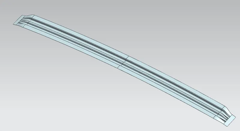
4) Rear roof rail:
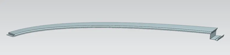
The rear roof rail is designed specifically to carry part of the snow load and provide an anchor point for the rear door hinge in this case. The design philosophy is similar to that of the front roof rail, though the gussets are made more pronounced to account for the weight of the car door.
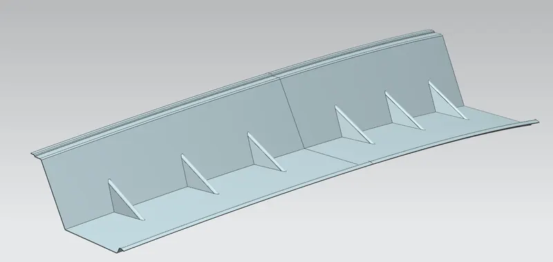
5) Bow roof rails:
Similar to the center roof rail, the bow roof rails are additional reinforcements given to the roof. The number of such rails really depends upon the size of the roof, the curvature of the roof, or the type of vehicle in which it is to be used. As a rule of thumb, bow roofs are assigned to locations where the curvature of the roof is relatively flat. In this case, since the front half of the roof has a significant curvature compared to the rear half, the bow roofs are assigned behind the center roof rail at suitable distances.
The design of both rails is similar to that of the center roof rail, albeit being narrower in width. Additional cutouts are made into sheet metal to make the mastic regions clearer for the assembler to figure out.
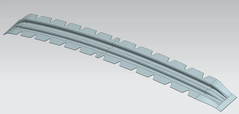
Front bow roof
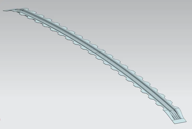
Rear roof rail
6) Assembly:
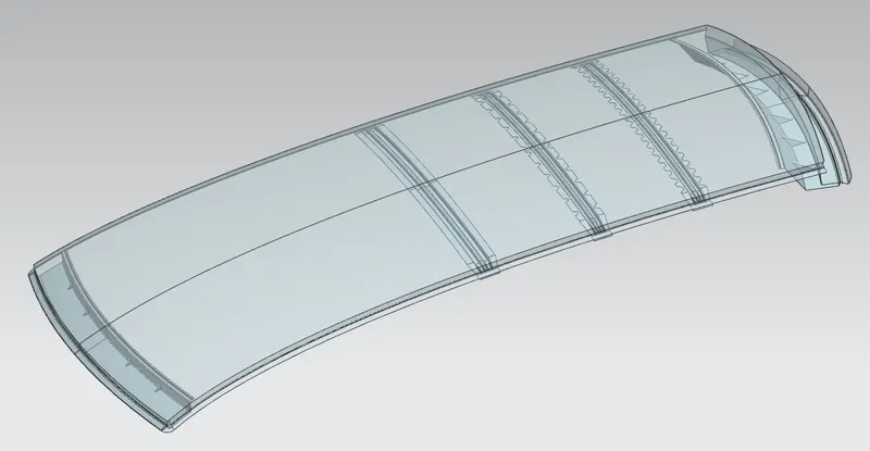
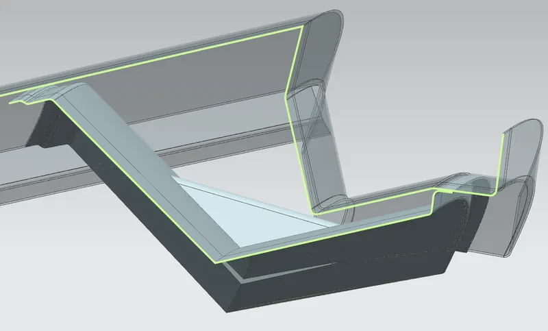
The modeled components are assembled as follows. Roof outer panel transparency is adjusted for better viewing.
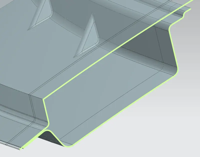
Front roof rail cross-section
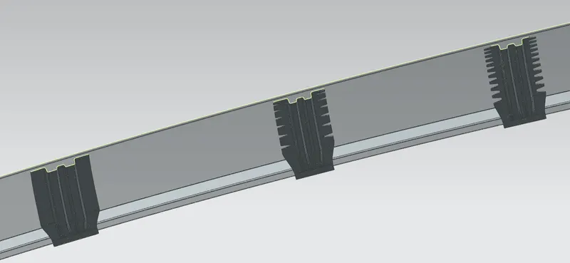
Centre roof rail (left), Bow roof front (middle), Bow roof rear (right)
Draft Analysis:
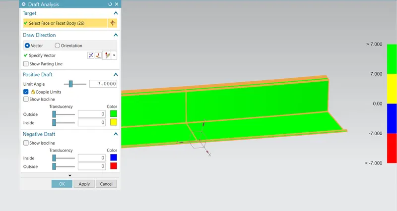
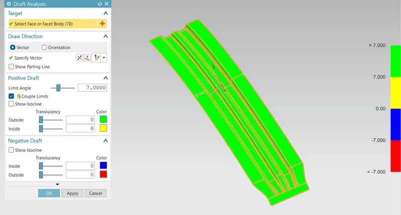
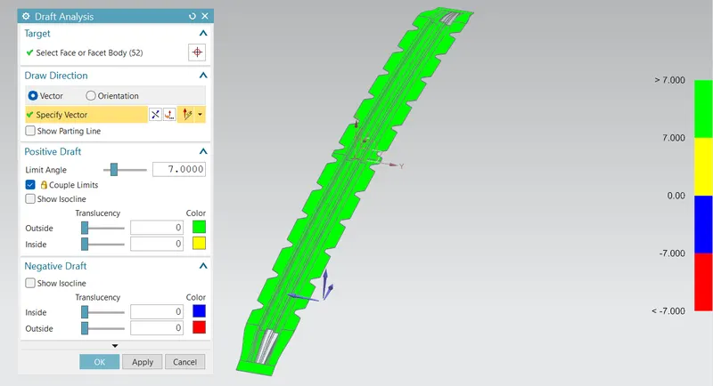
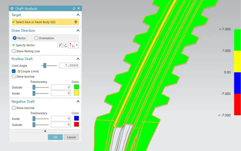
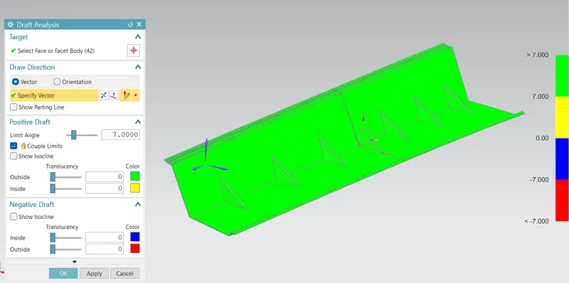
In any sheet metal manufacturing process, the draft angle is one of the most vital parameters that need to be taken into account. Sheet metal parts such as these are created using a punch and die combination. Draft allowances allow for the clean separation of the tool from the metal.
NX CAD has an inbuilt feature called Draft Analysis for this inspection. Initially, a datum coordinate system must be made to specify the draft direction. Then for a set angle, the software will show if the draft is positive or negative. Green and yellow signify a positive draft, which is desired. Whereas blue and yellow signify a negative draft, which must be rectified by increasing the angle between surfaces.
Heat distortion Criteria:
Heat distortion occurs when metals of minute thickness are subject to excessive temperatures for prolonged periods, causing them to warp and bend out of shape. This affects the shape of the sheet and can lead to drooping. The heat distortion criteria are based on providing enforcements at particular locations on the roof and checking whether these locations are suitable to prevent the sagging of sheet metal.
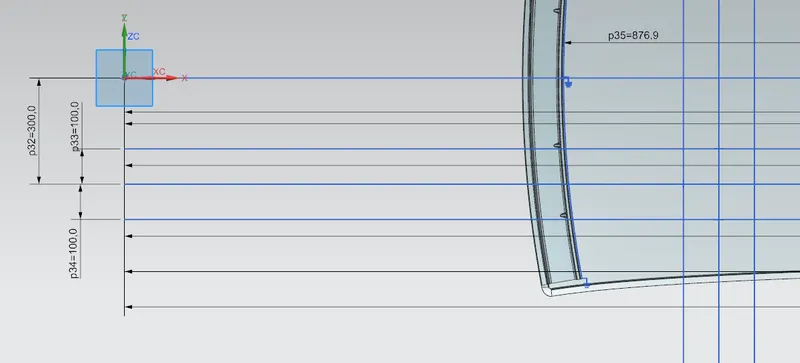
For the calculations, the local radius of the outer panel needs to be measured. For that, first an offset of 300 mm is given from the sheet centreline, with an additional 100 mm offset given on either side of this new line.
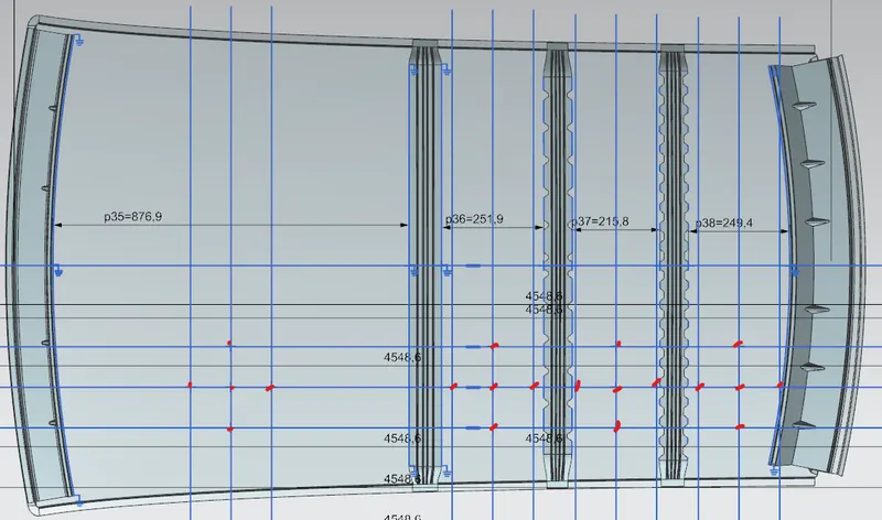
Next, the bisector of the edges of each of the reinforcements is drawn, with 100 mm offsets given to these 4 bisectors. We obtain the following intersection points marked in red. The distance between the reinforcements are also measured.
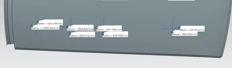
The points obtained are projected onto the outer panel surface. The diametrically opposite points are joined using the roof as the drawing surface and the local radius tool is used to measure the required radii.
Now, the following formula is applied:
W = [1.73x10^(-3)xL] + [1.85x10^(-8)x(R^2)/t] + [1.10x10^(-3)xl] - 2.68
Where,
L = Roof Length total
R = Roof curvature = 2(Rx*Ry)/(Rx+Ry)
Rx = Lateral Roof Curvature
Ry = Longitudinal Roof Curvature
t = Roof plate thickness [mm]
l = Distance between reinforcements
From this, the following results are obtained:

The value of 'W' must be less than 2.7, which is obtained for all cases. Hence the Heat Distortion Criteria are fulfilled. The result also shows where the value can be improved. For example, the value of 2.07 can be reduced if the center roof rail can be shifted slightly further, which will reduce 'W' by reducing 'I'.
Snow Loading Criteria:
Similar to the heat distortion criteria, the Snow Loading Criteria determines the ability of the reinforcements to withstand the weight of the snow in winter-dominant countries. If not properly calculated, the weight of the snow will make the sheet metal buckle. So the reinforcement location must be checked for this criteria.
The procedure is similar to that of the heat distortion criteria, but the points are now marked at the centreline instead of first giving a 300 mm offset. The remaining procedure remains the same.
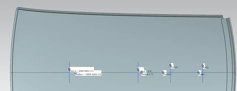
Section inertia analysis is also needed for the center and bow roof rails. First, a clip section is obtained along the length of the reinforcements (lateral direction of the roof surface), and an intersection curve is obtained. The curve is closed wherever open ends are present to finish a closed polygon. Section inertia analysis is performed on the polygon. The minimum moment of inertia (Min MOI) is considered.
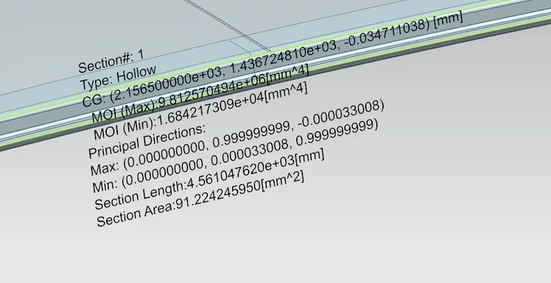
The formula for snow loading criteria is:
Qr = [Iy x t2] / [α x s x [(Rx + Ry)/2]2 x 10-8]
Where,
α = My x Lx2 x 10-12 , My = Y(Ly-Y)
t = Roof plate thickness [mm]
Ly = Length of Roof panel with the center point between Roof rail Front /Rear as the front and rear reference point [mm].
Lx = The width of the roof panel that is exposed on the surface [mm].
Y = Distance front Front Roof Rail to Roof reinforcement under consideration[mm].
s = Distance for which Roof BOW bears divided load [mm].
s = L1/2 + L2/2
Iy = Geometrical moment of inertia of Roof BOW (Y cross-section )[mm4]
Rx = Roof panel curvature local Radius of the panel in Front view.
Ry = Roof panel curvature local radius of the panel in Side view.
The results obtained are as follows:
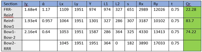
The judgment criteria is Qr > 3.1. Hence the roof assembly passes the snow loading criteria. Since Qr is relatively larger, it indicates that the design is well beyond the safety margin. In fact, only one bow roof can be placed instead of two bow roofs. But if it is the case, the heat distortion criteria must be recalculated and checked if it satisfies the new arrangement.
Conclusion:
The roof assembly was created keeping in mind the heat distortion and snow load criteria. Draft analysis was also performed o individual reinforcements to check for conformity.