Fender Design Challenge
Fender Design
Objective: To model an automobile fender using existing skin data, with inclusion of drip area and mountings at the A-pillar, bumper, sill and wheel well.
Introduction: The fender of an automobile is defined as the the part which covers the wheel well (usually the front wheels) of the vehicle. The purpose of having a fender is to offer protection from objects like stones, mud, water which are projected at various angles by a rotating tyre. During the initial days of automobile technology, the fender's use was just for protection from flying debris. Nowadays, a normal automobile fender extends beyond the length of the axle to take into account the turning of the front wheels.
Modelling of the Fender:
Skin data from the styling team is usually the first step towards creating the required part. In this case too, the skin data is used to model the fender.
The most important component within the fender which requires the utmost attention is the drip area. The drip area is an internal extension of the sheet metal, within the engine bay. This extension is given mainly for cosmetic reasons. Normally, there is always a gap between the hood and the fender to give sufficient room for the hood to be opened. But this gap creates an opening through which the engine bay is visible. This is unappealing cosmetically. So, by giving a drip area, the line of sight always ends on the sheet metal extension. The drip area also acts as a protection for some of the components which are sensitive to rain water.
To create the drip area, the dimensions required by the industrial standars are to be followed. In this case, it dictates that the drip area must begin at a distance of no more than 300 mm from the A-pillar, and must end 150 m away from the front end of the fender. Keeping these dimensions in mind, the drip area is created using simple law extension in NX CAD. The extensions are also subjected to pre-determined dimensions. The required face blends are given to the edges between faces to give realism. Tool workability is also taken into consideration, such that there must be atleast 200 mm between the open hood and the base of the drip area. After the drip area is modelled, the provision for fastening is made in the form of an emboss. In this case, the fastening method considered is bolt and nut. Special care is to be taken while modelling the surface for the emboss, since this surface needs to be flat. So during embossing operation, any curved surfaces cannot be taken as reference.
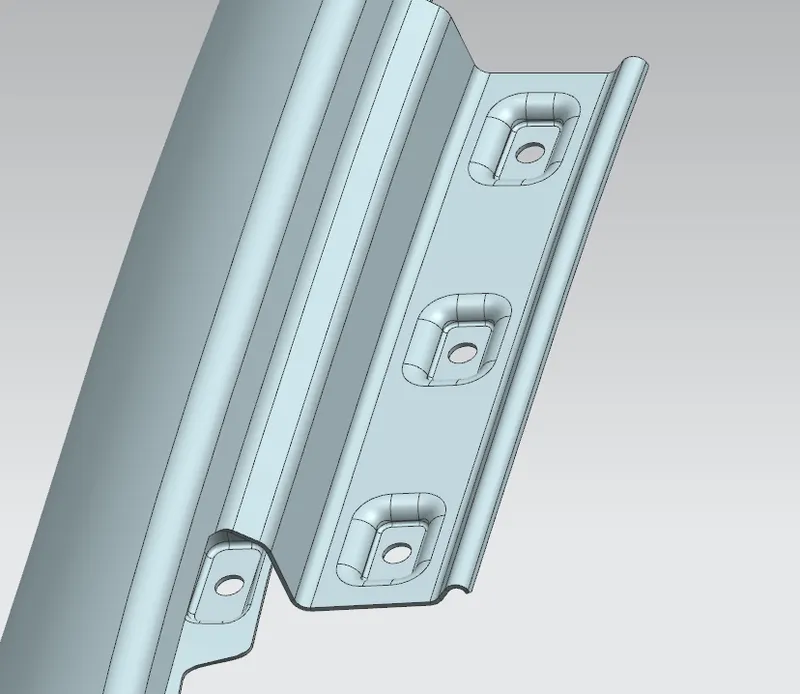
Drip Area
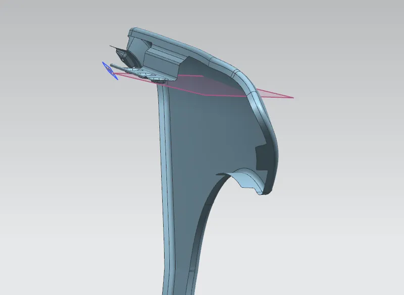
Plane taken as reference for the emboss feature
Similar approach for the other locations such as the A-pillar, sill and wheel well mountings.
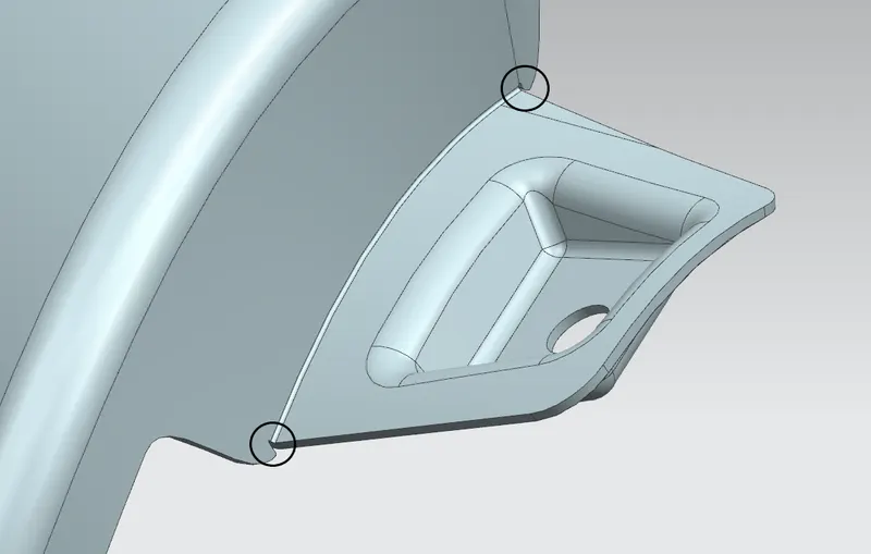
A-pillar mount. In cases where it is difficult to model a smooth curve between per mutually perpendicular surfaces, a different approach of making a relief (circled in the image above) can be made.
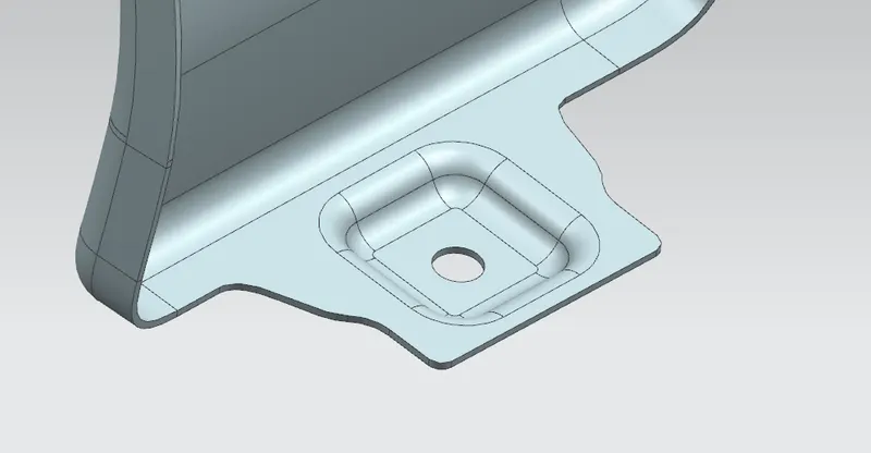
Sill Mount
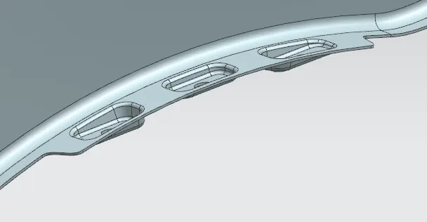
Wheel Arch mount
For the Bumper mount, the mounting surface is modelled perpendicular to the surface of the bumper. In reality, giving a flange to any sheet metal brings with it a risk of vibration leading to noise. Also, the flanged component becomes weaker. To avoid these from occuring, a feature called Gusset is used. It is a strengthening feature used on sheet metal edges to prevent warping and bending.
In NX CAD, this feature can be added using the DART command. The command takes the depth, angle and radius of the Gusset as input. It is also possible to position the Gusset along a specified length along the edge.
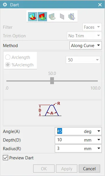
After the required dimensions and position is given, the commend generates a Gusset.
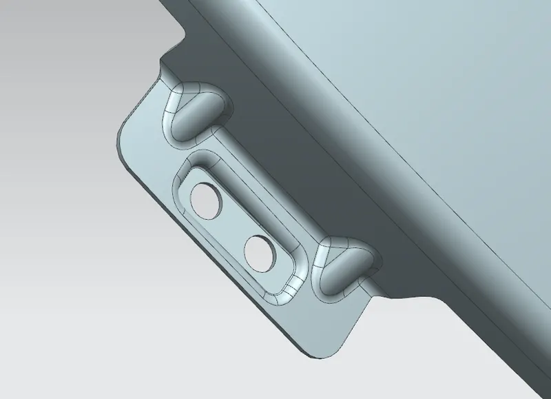
Bumper Mounting
After the creation of all the mountings, the entire model is thickened by 0.75 mm to accurately simulate sheet metal.
Conclusion:
1) The drip area for the fender was designed by adhering to the given dimensions. Considerations such as tool workability and flat mounting surface were also made.
2) Mountings at A-pillar, Sill, Wheel Arch and Bumper were modelled.
3) Special feature DART was also studied for the creation of Gussets.