Roof challenge
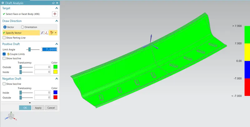
AIM: To design a roof with all its components i.e. the front roof rail, bow roofs, center roof rail and rear roof rail by following the master sections and check for draft analysis also do the section inertia and curvature study.
ROOF:
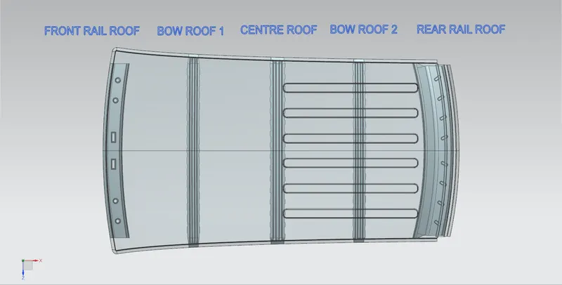
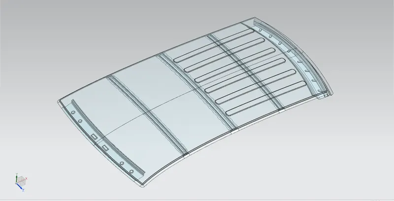
The roof or top is the portion of an automobile that sits above the passenger compartment and it protects the occupants from various environmental conditions like heat, snow, rain, and winds. There are many types of the roof which differs based on the variants of the car and the region. The roof must be designed in such a way that it would able to withstand load or impact due to accidents or objects falling on it and other environmental factors, other factors like headroom, aesthetics play a role in the design. The roof is an assembly of many parts like Front roof rail, Bow roofs, Centre roof rail, and Rear roof rail. The number of bow roofs is based on the length of the roof and sometimes even the bow roof center is avoided in cases like small cars. The roof is attached to the body of the car using mastic sealants provided between bow roofs and the front and rear rails. Roof is connected to A-pillar, B-Pillar and C-Pillar to cover the front and rear door.
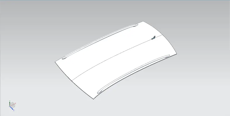
The Components of Roof:
- Front Roof Rail
- Bow Roof 1
- Centre Roof Rail
- Bow Roof 2
- Rear Roof Rail
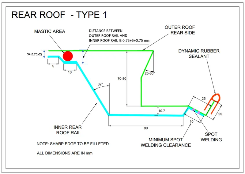
MASTER SECTIONS:
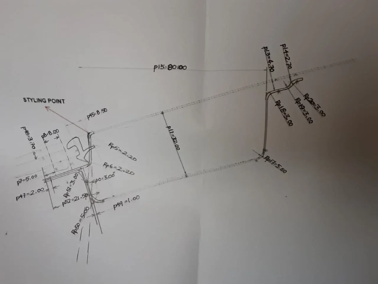
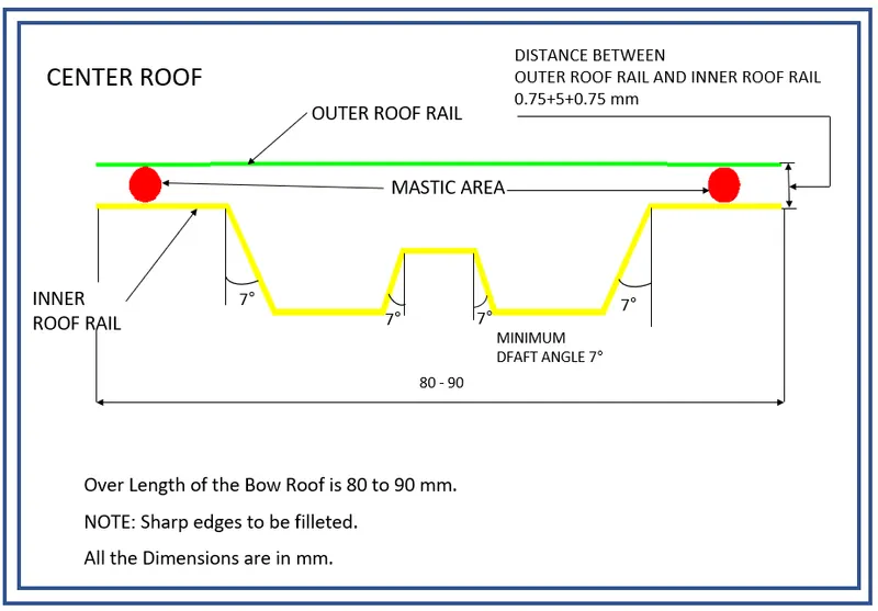
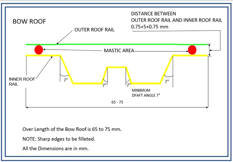
All the components and flanges are designed according to the master sections and follow the dimensions in it.
FRONT ROOF RAIL:
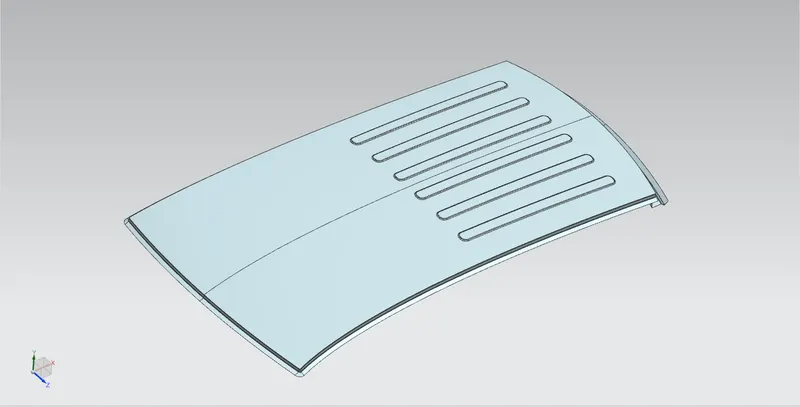
Roof Outer Panel
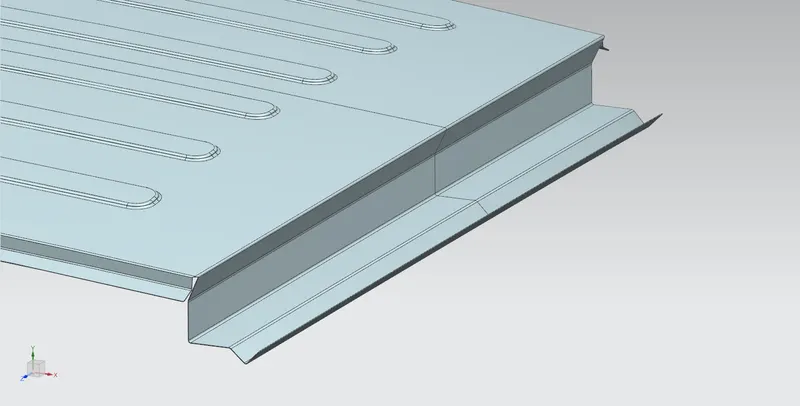
Front Roof Rail
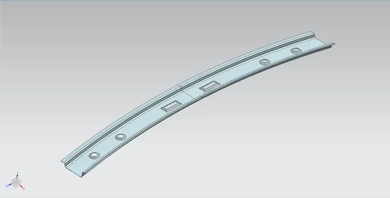
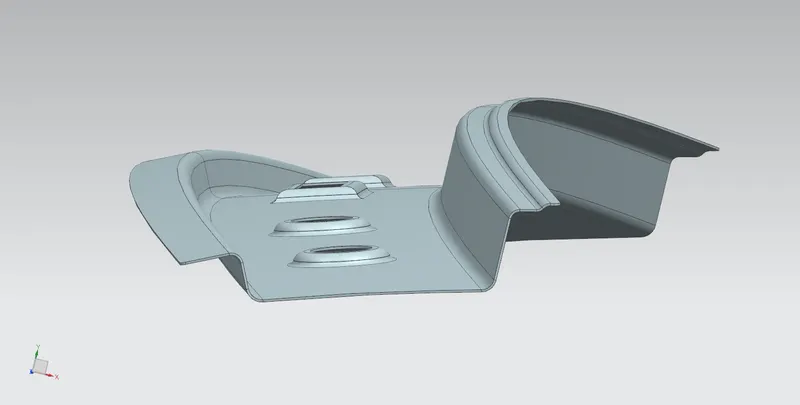
Bow Roof 1
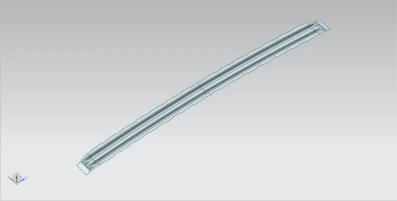
Centre Roof Rail
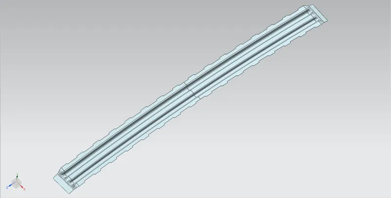
Bow Roof 2
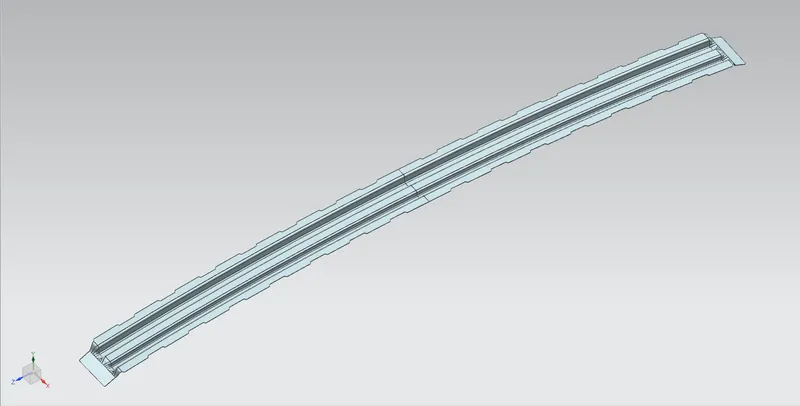
Rear Roof Rail
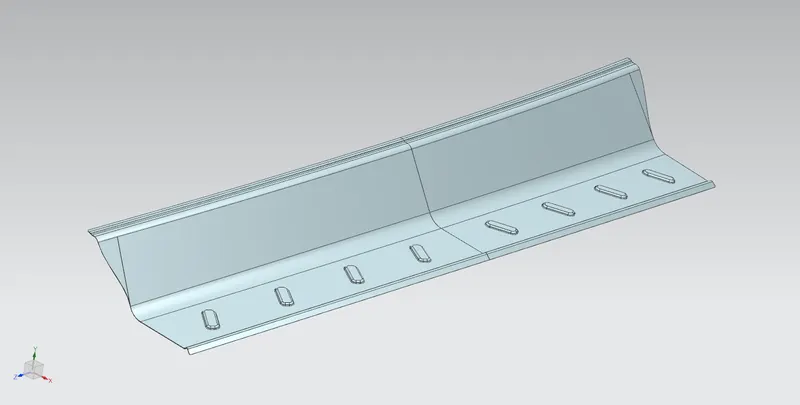
ROOF ASSEMBLY
BOW-ROOF PREDICTION FORMULA:
W = [1.73 x 10⁻³ x L] + [1.85 x 10⁻⁸ x R2/t] + [ 1.10 x 10⁻³ x l] - 2.68
Judgment Condition
OK< 2.7
Where,
L = Roof Length in X-Direction[mm](Roof dimension in 0-Y)
R = Roof curvature
R = 2(Rx×Ry)/(Rx+Ry)
Rx = X curvature
Ry = Y curvature
t = Roof plate thickness [mm]
l = Bow Roof Span [mm]
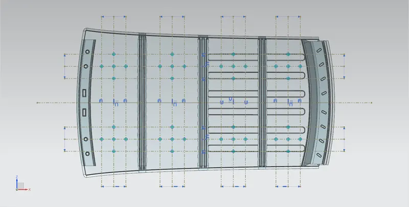
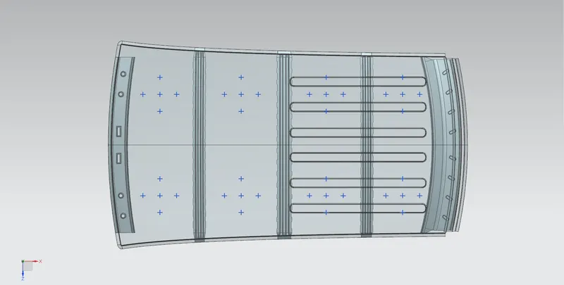
| S.No | BOW |
Rx |
Ry |
R | l | L | t | R2/t | W | OK/NG |
|---|---|---|---|---|---|---|---|---|---|---|
| 1 | Front-1st Bow | 2522.8162 | 5739.6016 | 3505.0175 | 389.6327 | 2033.7048 | 0.75 | 16.3801×10⁶ | 1.5699 | OK |
| 2 | 1st Bow-Centre | 6267.0081 | 4955.0142 | 5534.3169 | 421.4924 | 2033.7048 | 0.75 | 40.8382×10⁶ | 2.0574 | OK |
| 3 | Centre-2nd Bow | 10552.3977 | 2431.0168 | 3951.6655 | 406.2750 | 2033.7048 | 0.75 |
20.8208×10⁶ |
1.6703 | OK |
| 4 | 2nd Bow-Rear | 14468.3036 | 2783.0713 | 4668.1868 | 347.3025 | 2033.7048 | 0.75 | 29.0559×10⁶ | 1.7578 | OK |
SNOW LOAD PREDICTION FORMULA:
Qr = [Iy x t2] / [α x s x [(Rx + Ry)/2]2 x 10-8]
Judgment condition
Qr ≥ 3.1
250 ≤ s ≤ 380
Where,
α = My x Lx2 x 10-12 , My = Y(Ly-Y)
t = Roof plate thickness [mm]
Ly = Distance between the front and rear roof Rails on the Vehicle along with 0Y[mm]
Length of Roof panel with the center point between Roof rail Front /Rear as the front and rear reference point.
Lx = Distance between the Left and Right end of the roof on the Roof BOW [mm]
The width of the roof panel is exposed on the surface.
Y = Distance from Front Roof Rail to Roof BOW[mm]
s = Distance for which Roof BOW bears divided load [mm]
s = L1/2 + L2/2
Iy = Geometrical moment of inertia of Roof BOW (Y cross-section )[mm4]
Rx = Lateral direction curvature radius of roof panel Y cross-section on Roof BOW [mm]
Roof panel curvature Radius of the Length Lx in Front view
Ry = Longitudinal Direction curvature radius of the Roof panel X cross-section on Roof BOW [mm]
Roof panel X curvature radius of length s in Side view
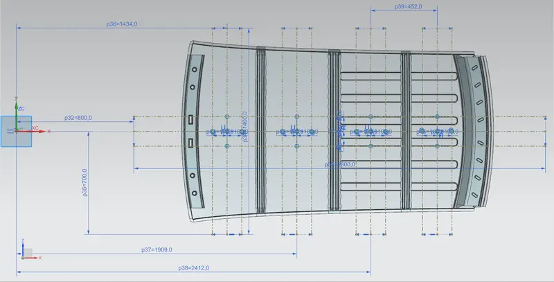
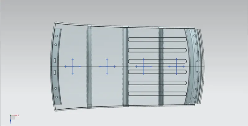
| S.NO | BOW | Iy | α | Lx | Ly | Y | s | Rx | Ry | t | Qr | Determination (Qr) |
|---|---|---|---|---|---|---|---|---|---|---|---|---|
| 1 | Front-1st Bow | 234.3731 | 0.97 | 1137.4147 | 2033.7048 | 489.5 | 496 | 2612.7699 | 4522.0002 | 0.75 | 2.15 | NG |
| 2 | 1st Bow-Centre | 245.7732 | 0.90 | 1086.4165 | 2033.7048 | 502.5 | 495.35 | 6169.9630 | 3767.3657 | 0.75 | 1.25 | NG |
| 3 | Centre-2nd Bow | 234.4053 | 0.84 | 1058.5443 | 2033.7048 | 488.2 | 487.35 | 11038.4044 | 16962.9274 | 0.75 | 0.16 | NG |
| 4 | 2nd Bow-Rear | 0.82 | 1044.4469 | 2033.7048 | 486.5 | 16227.6217 | 13381.7292 | 0.75 |
SECTION INERTIA STUDY:
Section Modulus:
- Section Modulus is the geometric property of the given cross-section of any shaft or beam structures
- It is the direct measure of the strength of the shaft section or the beam section
- Higher the section modulus of a structure, the more the resistive it becomes to bending
- It is the ratio of total moment resisted by the section to the stress in the extreme fibre
- It gives us an idea about how much of load the given structure can take
Section Modulas can be calculated by the formula:
S = I/y
Where, S = Section Modulus
I = Moment of Inertia
y = distance between the neutral axis and the extreme end of the object
FRONT ROOF RAIL:
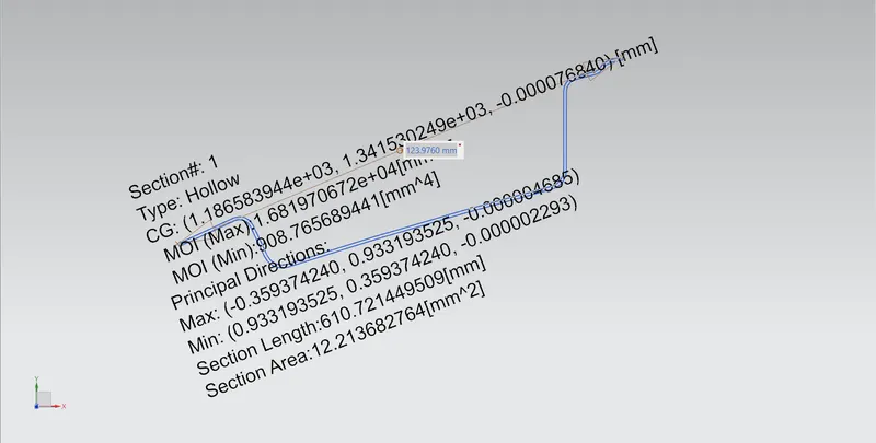
Imax = 1.6819×104 mm4
Imin = 908.7656 mm4
y = 123.9760/2
= 61.988 mm
S = I/y
= 908.7656/61.988
S = 14.6603 mm3
BOW ROOF 1:
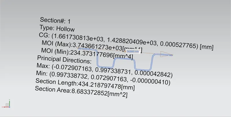
Imax = 3.7436×103 mm4
Imin = 234.3731 mm4
y = 74.8960/2
= 37.448 mm
S = I/y
= 234.3731/37.448
S = 6.2586 mm3
CENTRE ROOF:
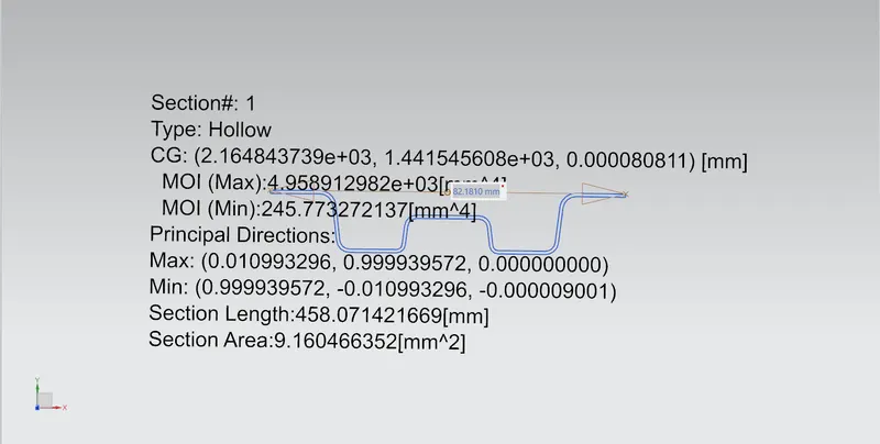
Imax = 4.9589×103 mm4
Imin = 245.7732 mm4
y = 82.1810/2
= 41.0905 mm
S = I/y
= 245.7732/41.0905
S = 5.9812 mm3
BOW ROOF 2:
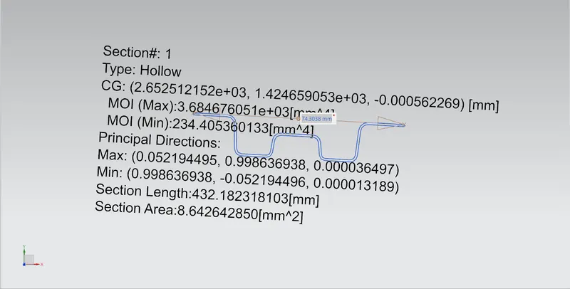
Imax = 3.6846×103 mm4
Imin = 234.4053 mm4
y = 74.3038/2
= 37.1519 mm
S = I/y
= 234.4053/37.1519
S = 6.3093 mm3
REAR ROOF RAIL:
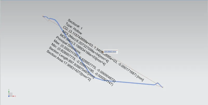
Imax = 6.2073×104 mm4
Imin = 3.1989×103 mm4
y = 201.9963/2
= 100.9981 mm
S = I/y
= 3.1989×10³/100.9981
S = 31.6728 mm3
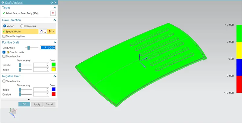
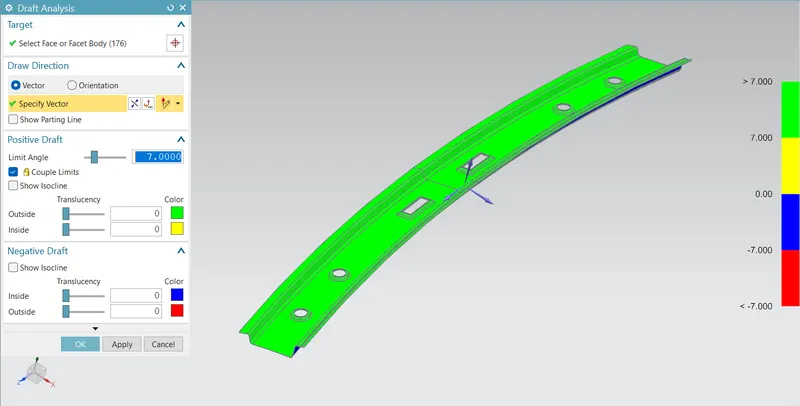
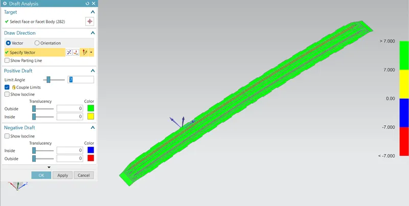
DRAFT ANALYSIS:
Roof Outer Panel
Front Roof Rail
Bow Roof 1
Centre Roof Rail
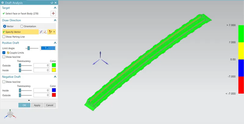
Bow Roof 2
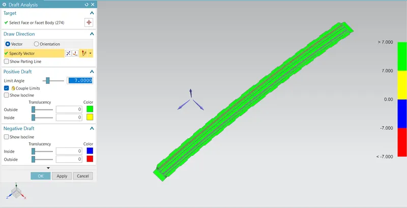
Rear Roof Rail