Week 12 Challenge
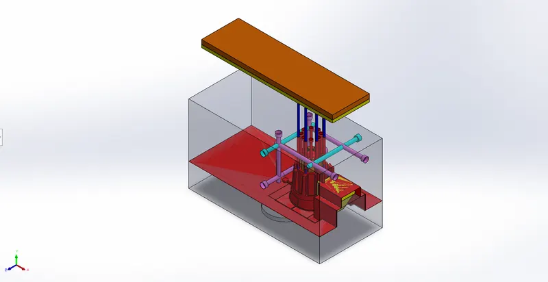
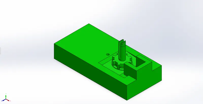
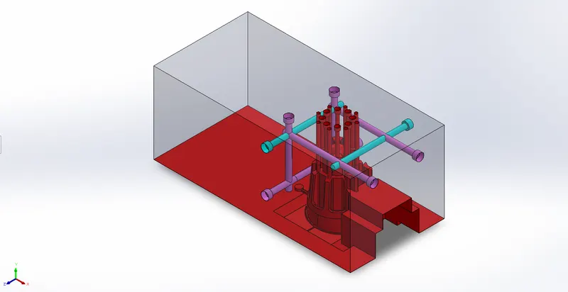
Procedure followed to create the Plastic Knob mold blocks:
- Decide tooling direction and check for draft analysis
- Scale the model considering 0.6% shrinkage i.e. 1.006
- Close the open surfaces using shut off surfaces, keep the bottom open surfaces as no-fill. Use loft surfaces for closing no-fill portion and then knit them
- Create a tooling plane and create the split lines
- Create the parting surface using ruled surface command and knit them together
- Use move/copy body command to create copies
- Knit the parting surfaces with core/cavity surfaces
-
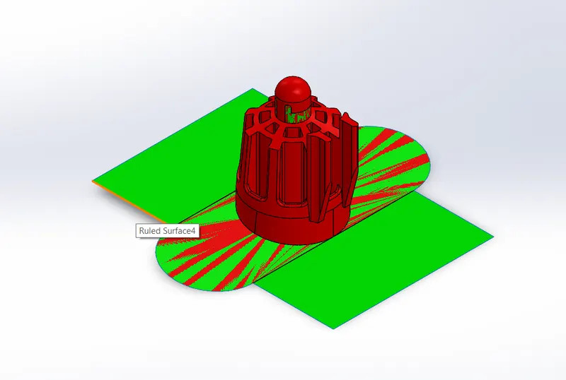
- Align the sprue at its location
- Create the inner/outer core blocks using boss extrude. Then use split command to seperate inner/outer block
- Offset the core/cavity surfaces and use cut with surface to form the respective blocks
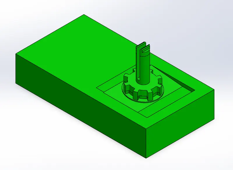
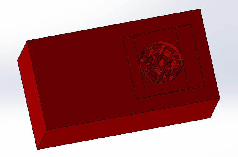
- Provide relifs on faces with direct contact using move face command
- We will have to create inserts for the inner features since the depth is more than 50mm and the cutting tool for this length is not available
- Select the top plane and click on the insert's profile than use convert entities to form the sketch. Then use split command to form inserts
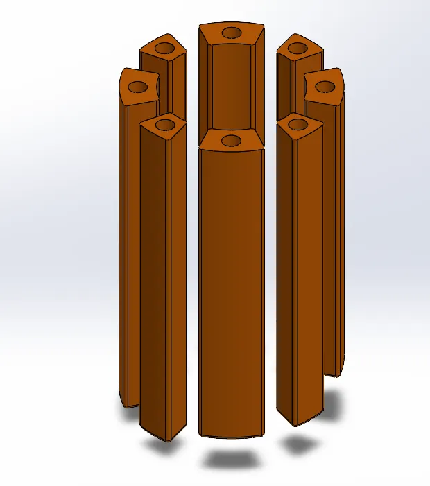
- Use hole wizard command to form holes for bolts for fixing inserts also create holes in inserts using extrude cut
- To form the sliders add a plane at 60mm from top surface and sketch the profile such that the undercuts get covered and then use split command to seperate slider profile from cavity block
- Use boss extrude to add material and use extrude cut to form the wedge for slider. Insert into new part
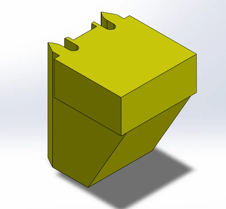
- Use combine command to form the slider profile in blocks
- Make necessary edits in the core & cavity blocks to ensure proper fit and easy movement of slider
- Provide relif between core/cavity block faces which are in direct contact
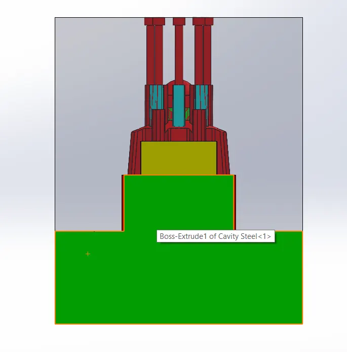
- To create the ejector pins sketch 6mm circles and extrude them.Provide proper relif and holes in core block also create pin head
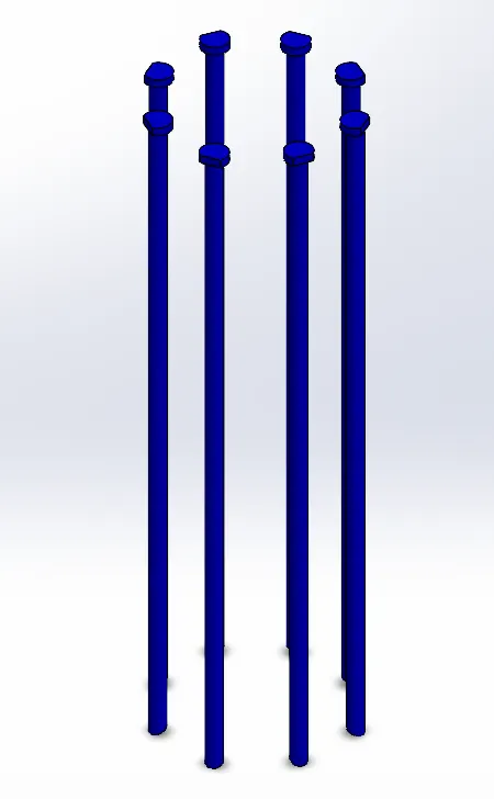
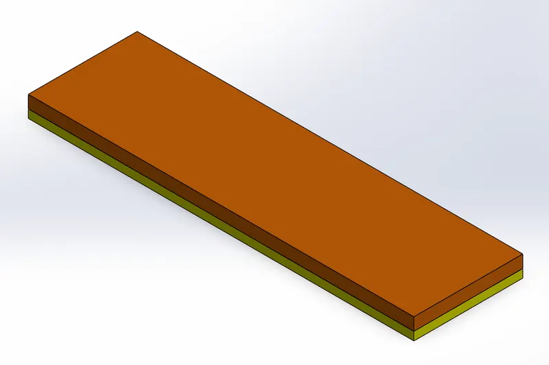
- Select pin head surface and sketch rectangles to form ejector plates. Also, provide pin head relif on plates
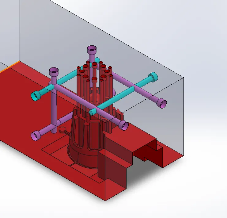
- Now in cavity block sketch circle and extrude cut to form sprue. Use extrude cut,draft,extrude boss,fillet,combine commands to create the runner and gate system
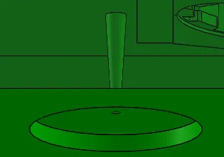
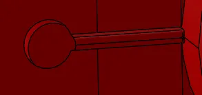
- Create air vents in the core block use extrude,fillet,mirror & combine commands
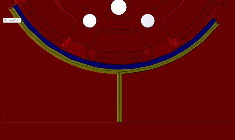
- Now to make the cooling channel across the core block use hole wizard command and specify M10 socket head cap screw type and create multiple cooling channels