Roof challenge
Design of Roof
Objectives
1. For the Given Roof styling, Develop the essential flanges and reinforcements, provideappropriate dimension and check for Draft analysis and also submit your section modulus report on the 0-Y section.
2. Start with the creation of a roof ditch area the tool opening angle is only 3 degrees.
3. Do a curvature study on the roof and perform calculations to determine thee position of the Bow-roof
Introduction-
An automobile roof or car top is the portion of an automobile that sits above the passenger compartment, protect the vehicle occupants from sun, wind, rain, and other external elements. Because the earliest automobiles were designed in an era of horse-drawn carriages, carly automobile roofs used similar materiais and designs.
Types of Car roofs-
- Convertible roofs
- Hardtops
- Sunroofs
- T-tops
- Targa tops
- Vinyl roofs
Safety point of view vehicle roof plays very crucial role specially roll over kind of accidents, in which vehicle tips over onto its side of roof. And vehicle rollover crashes are the causes of many fatalities and several head, neck and spine trauma around the world. Therefore, passenger safety is also very important parameter in front of OEM's. It is not only a marketing strategy but also it isa obligation stipulated by international standards that are now place in severa countries, as well as a governmental requirement.
Rollover crashes, especially in the country, are usually very destructive events. Vehicle damage often includes deformation of the roof and its supporting structures. Head and neck injuries are common, and associated with roof deformation. Strengthening of the roof is suggested as an appropriate countermeasure for such injuries.
Types of Rollovers
1. Tripped-NHTSA data show that 95% of singte-vehicle rolovers are tripped. This happens when a vehicte leaves the roacway and slides sideways, digging its tires into soft soil or striking an object such as a curb or guardrail. The high tripping force applied to the tires in these situations can cause the vehicle to rolil over. E.g. Soft soit Guardrail, Steep Slope
2. Un-Tripped -Un-tripped rollovers are less common than tripped rollovers, occurring less than 5% of the time, and mostly to top-heavy vehicles. Instead of an object serving as a tripping mechanism, un-tripped rolovers usually occur during high-speed collision avoidance manoeuvres.
For this reason, strength is very important criteria for designing vehicle roof.
EMVSS 216 Roof crush standards
FMVSS 216, Roof Crush Resistance, establishes strength requirements for the passenger compartment roofof passenger cars, multipurpose passenger vehicles, trucks and buses with a GVwR of 2722 kilograms or less. The purpose of the standard is to reduce deaths and injuries due to the crushing of the roof into the passenger compartment in roliover accidents. The standard does not apply to school buses and passenger cars that conform to the dynamic rollover test requirements of FMVSS 208, Occupant Crash Protection, and $5.3 by means that require no action by passenger car occupants. It also does not apply to convertibles, except for optional compliance with the standard as an alternative to the rollover test requirements in S5.3 of FMVSS.
The prescribed static loading device is a rigid unyielding rectangular block 762 millimetres by 1,829 milimetres. It shall not move more than 127 millimetres to achieve the specified resistive load when applied to the forwarad edge of a vehicle's roof see Figuresl and 2. The resistive load to be achieved is 1% times the unloaded vehicle weight (UVw) of the test vehicle or 22,240 Newtons, whichever is less.
The force shall be applied in a downward direction perpendicular to the lower surface of the static load a rate of not more than 13 milimetres per second until reaching the compliant resistive load. The test shall be completed within 120 seconds. The static loading device shall be guided throughout the test so that it moves, without rotation, ina straight line with its lower surface orientod as follows
Desinging of components of Roof
1.desinging of ditch area flange
We will start first by exctracting surface from input data solid roof part. Using this surface we design ditch area flange
2.Design of front roof rail
For designing front roof rail we need to consider some parameter which are as discussed below
a.Visibility of the driver and passenger
We always keep in mind while designing the front roof we do not reduce the visibility available to driver. While designing front roof one must stick to the master section dimensions because little change in dimension will have impact on the visibility of the driver (eg small change in angular dimension willead to large change in linear dimension)
b. Head room There should be enough space between roof rail and head position of driver so when accident will happen head will not hit to the front roof rail.
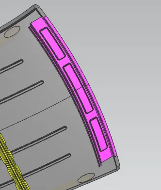
3.Design of Rear roof rail
Rear roof rail is also desinged same as front roof rail
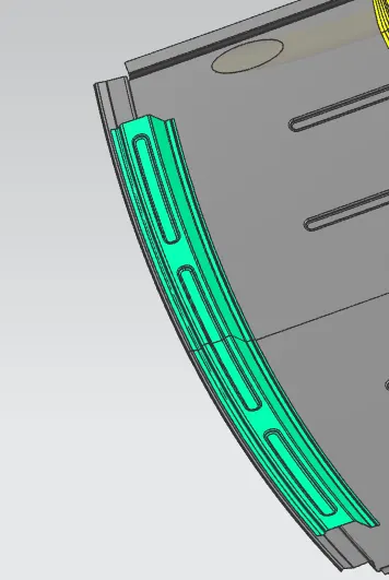
4. Design of centre roof rail
Following same design process as front and master section we design center roof rail
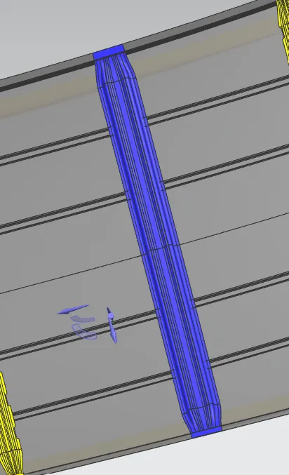
5.Design of Bow roof rail 1&2
Bow roof is sheet metal component which is used to add more structural strength to the roof. On the basics of the curvature of the roof bow roof is provided.
To justify the position of the bow roof there are two criteria are used
a.Heat distortion criteria
b.Snow load criteria
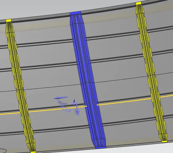
complete model
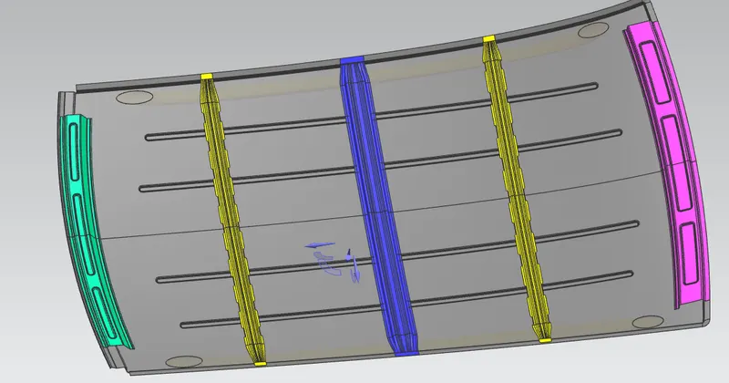
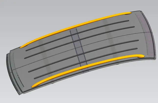
Bow roof rail calculations-
1. Heat Distortion caiculations
W =[173 x10^(-3) xL]+[1.85x 10^(-8) x (R^2)/t]+[1.10x10^(-3) x l]-2.68
Judgement Condition: OK <2.7>3.1
Where
L =Roof Length in X-Direction [mm](Roof dimension in 0-Y)
R= Roof curvature
R= 2(Rx*Ry)/ (Rx+Ry)
Rx = X curvature
Ry = Y curvature
t =Roof plate thickness [mm]
I = Bow Roof Span [mm]
Procedure to measure the parameters-
a.On plane parallel to the top plane draw sketch in which 0Y line is offset by 300 mm (3v) on both the sides of OY line.
b. Draw lines perpendicular to OY line passing through point exact midpoint of the two adjacent parts (e.g. midpoint between front rail and bow roof 1)
c. Offset these reference lines on both sides by 100 mm
d. Mark intersectionpoints (red points) of reference line (Yellow lines) and 100 mm offset lines(Blacklines)
e.These reference point are then projrcted on to roof outer panel surface to create curve
f.Take all neccessary measurements required to calculate W values as per mentioned formula
HEAT DISTORTION CRITERIA CALCULATION
| Roof rail span from | L(mm) | Rx(mm) | Ry(mm) | Rx*Ry | Rx+Ry | R | t(mm) | l(mm) | W | Result |
| FR-BOW1 | 2111.9154 | 5722.1317 | 2776.5212 | 15887619.97 | 8498.6529 | 3738.856066 | 0.75 | 457.5113 | 1.8216692508 | OK |
| BOW1-CR | 2111.9154 | 4894.8842 | 6508.5153 | 31858428.71 | 11403.3995 | 5587.531807 | 0.75 |
388.9774 |
2.171594737 | OK |
| CR-BOW2 | 2111.9154 | 3932.5371 | 10811.5819 | 42516946.93 | 14744.119 | 5767.309248 | 0.75 | 419.0352 | 2.255011476 | OK |
| BOW2-RR | 2111.9154 | 3234.7995 | 14889.3187 | 48163960.69 | 18124.1182 | 5314.902513 | 0.75 | 416.3743 | 2.1284414027 | OK |
2.Snow load criteria calculations
Snow load criteria is useful to justify the bow roof rail position in snow fall regions. Due to snow fall snow will get collected on the top roof which will tend to bend the roof. Bow roof will be at such position which will provide more strength to roof against bending.
Qr= [ly x t2] /[ax s x [(Rx+ Ry)/2)2 x 10-8)
Note: The Qr value given over here is correct. There was a typo error in the formula given in the video.
Where a= My x Lx2 x 10-12, My= Y(Ly-Y)
Judgement condition = Qr >= 3.1
250 <= s <= 380
t = Roof plate thickness [mm]
Ly= Distance between the front and rear roof Rails on the Vehicle along with 0Y[mm]
Length of Roof panel with the center point between Roof rail Front /Rear as the reference point of the front and the rear.
Lx = Distance between the Left and Right end of the roof on the Roof BOW [mm]
Width of the roof panel exposed on the surface.
Y = Distance front Front Roof Rail to Roof BOW[mm]
s = Distance for which Roof BOW bears divided load [mm]
s = L1/2 + L2/2
ly = Geometrical moment of inertia of Roar BOW (Y cross-section )[mrn4]
Rx= Lateral directlon curvature radius of roof panel Y cross-section on Roal BOW [mm]
Ry = Longitudinal Direction curvature radius of the Roof panel X cross-section on Roof BOW [mm]
Roof panel X curvature radius of length s in Side view
a.On plane parallel to the top plane draw sketch in which 0y is projected along the direction perpendicular to top plane.
b.Draw lines perpendicular to 0Y line passing through point exact midpoint of the two adjecent parts
c.Offset these reference lines on both sides by 100mm.
d.Mark intersevtion points of reference line and 100 mm offset lines.
e.These reference points are then projected on to roof panel surface to create curves
f.Take all necessary measurments required to calculated QR values as per mentioned formula

DRAFT ANALYSIS:-
1.Front Roof Rail 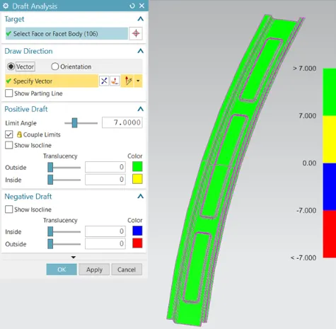
2.Bow Roof Rail 1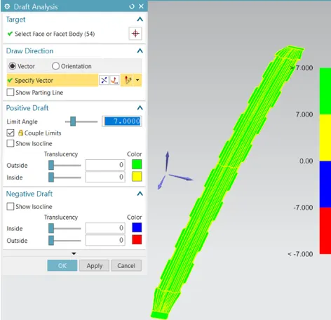
3.Centre Roof Rail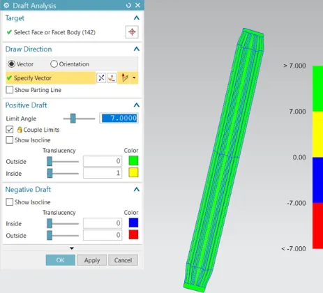
4.Bow Roof Rail 2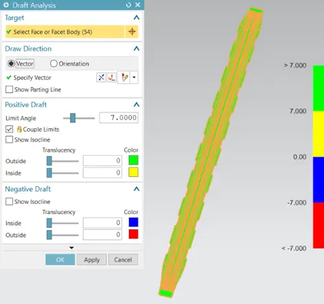
5.Rear Roof Rail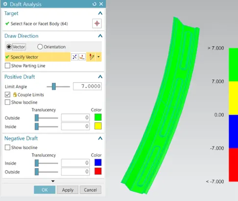
GOOGLE DRIVE LINK:-
https://drive.google.com/file/d/1DtUxot44h35mQhAQO62OV95cF7k0Y12Y/view?usp=sharing