Roof challenge
Aim: To create the Roof and its essential flanges and reinforcement.
Software used: CATIA V5.
Objectives:
- Design the roof from the given styling surface with Front and Rear roof rails.
- Create the Bow roof rails and center Bow with reinforcement.
- Do a curvature study on the roof and validate the design by applying the Heat distortion criteria and Snow Load criteria.
- Perform the section modulus.
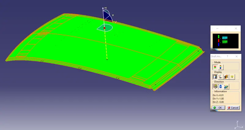
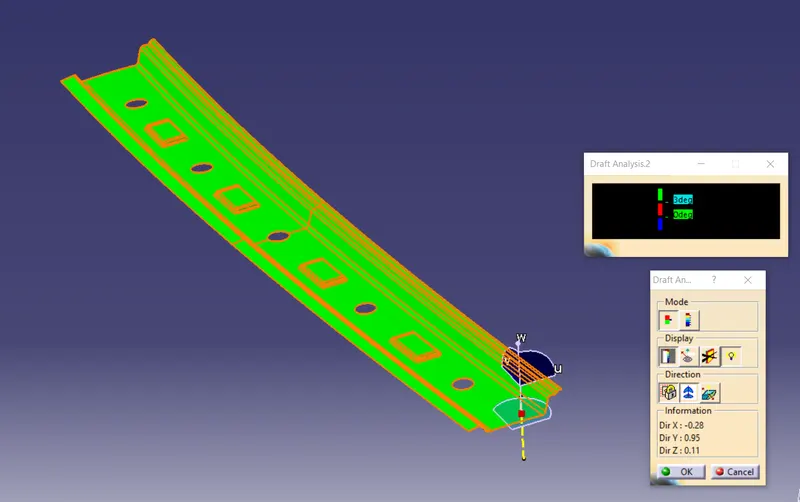
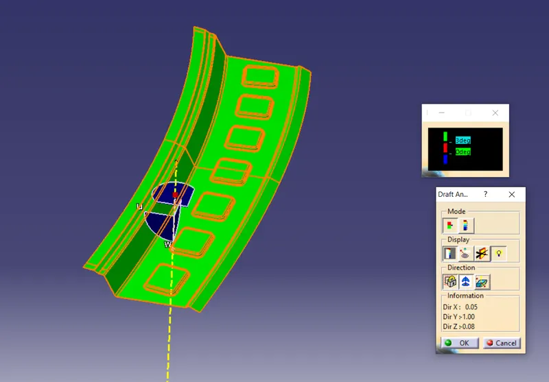
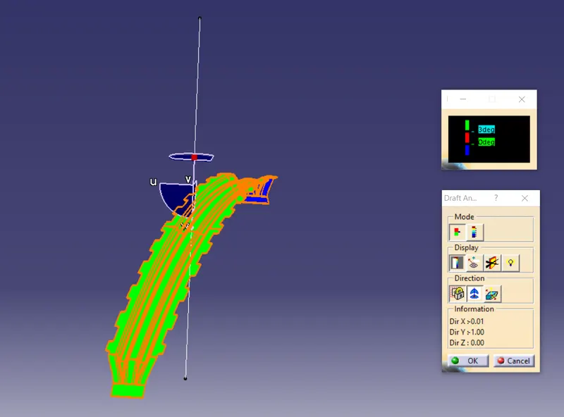
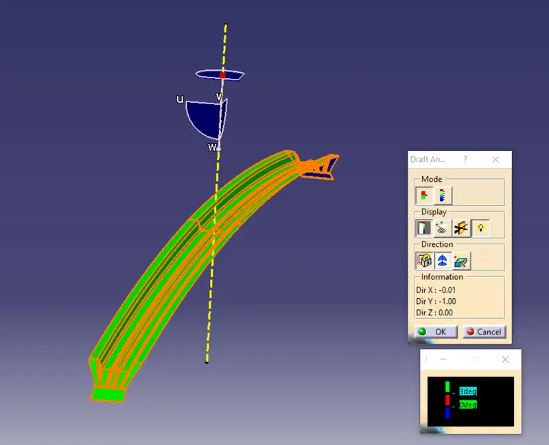
- Perform the draft analysis.
Note: All the parts created with the proper tool opening draft angle of of 3 Degrees and more than 3 Degrees.
Introduction:
An automobile roof or car top is the portion of an automobile that sits above the passenger compartment, protecting the vehicle occupants from sun, wind, rain, and other external elements.
The roof is a styling surface part which is fixed with the BIW body through the rails and panels inside the upper roof to provide it strength and stiffness.
Ditch area plays an important role here to fix the reinforcement on the component.
The rails and reinforcements are joined to the ditch area with a spot weld where it's not the styling part.
The required tool opening angle is minimum 3 Degrees.
Factors which is considered before creating Ditch area,
- Headroom clearance
- Visibility criteria
- Back door assembly
- Windshield assembly
Procedure:
Front and Rear end Ditch area:
- Ditch area which is most important where all the bow roof rails and panels are coupled on the BIW body through the ditch area.
- From the given Class A it is shown that the surface has discontinuity and the roof is exactly symmetric from the YZ plane.
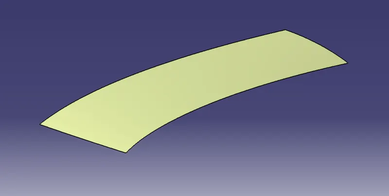
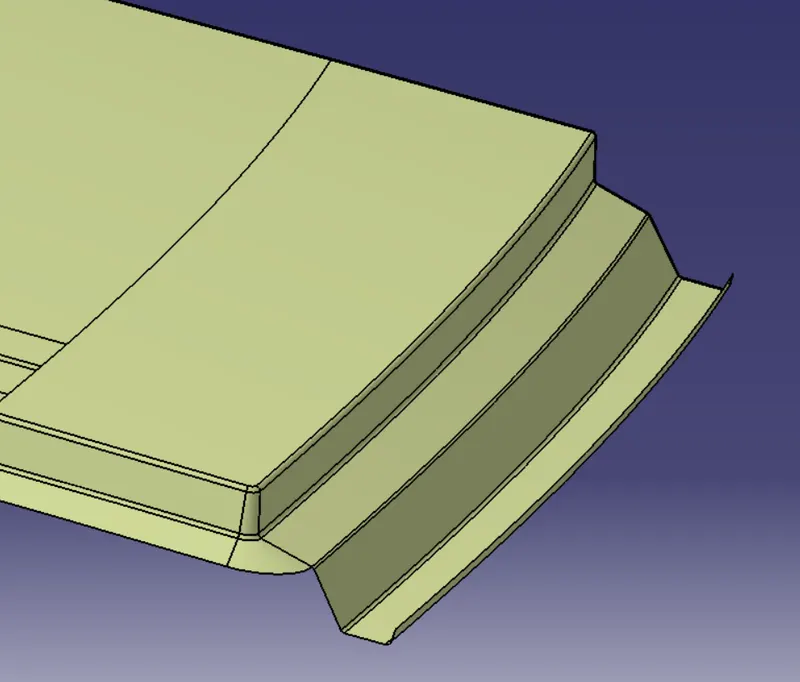
- Since the roof surface has sharp corners, first we need to give smooth corners to it, for that I used a corner command and gave a 5mm arc radius split it with the surface.
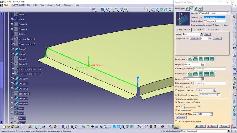
- Next I used the sweep command by selecting the edges to make the flanges by a draft angle of 3 Degrees and we can also give them more than 3 Degrees of the length of 15mm.
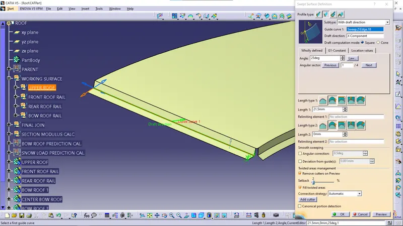
Again use a sweep command from the edge and give 25 degrees draft of the length of 21.5mm and do the same process on the other end of the roof.
After that I give multi section surface commands to the corners to join the rear end and front end with the side flanges.
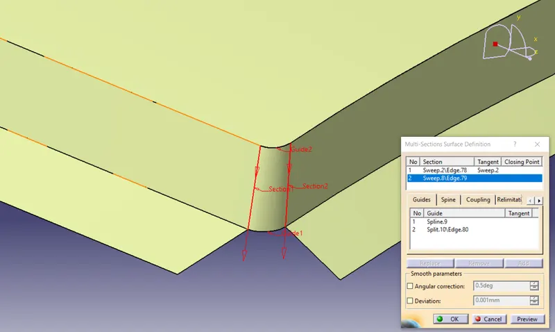
Then the rear end ditch area is going to be fixed with the back door of the car. So we created the additional flanges to hold the back door without hitting the roof.
Front Roof Rail:
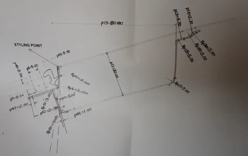
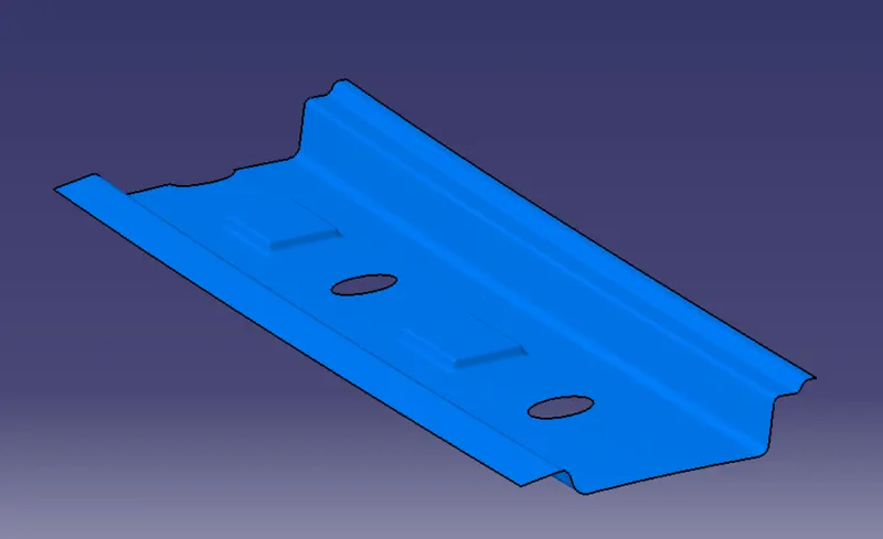
- Offset the upper roof surface by 2.7 and 4.7 and cut it by 5mm and 10mm respectively.
- Now offset the flange surface by 1.7mm maintaining the 0.2mm gap and thickness of 0.75mm of the parts.
- Then join the surface by using a sweep and trim it each other to get the front roof rail.
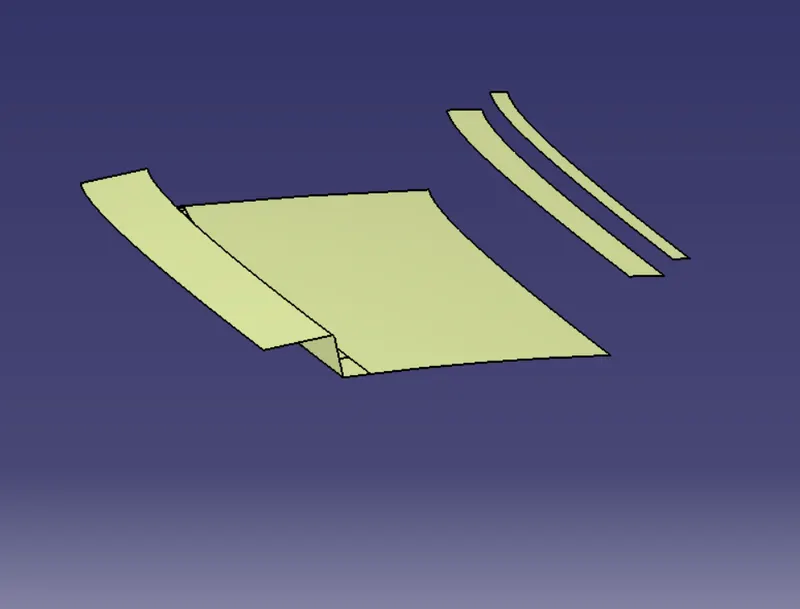
After that provide the fillets to get the final component.
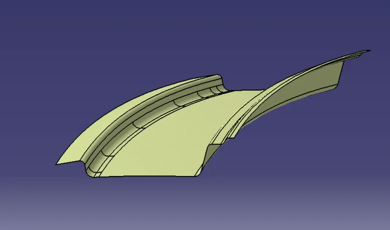
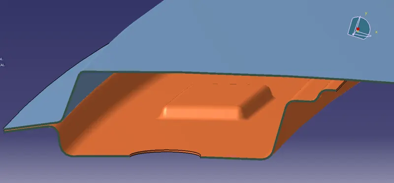
Give Emboses and holes to provide strength to the component.
Rear Roof Rail:
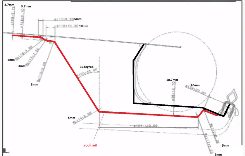
For the rear roof rail I repeated the same procedure from the above along the master section of rear roof rail.
Bow roof rail:
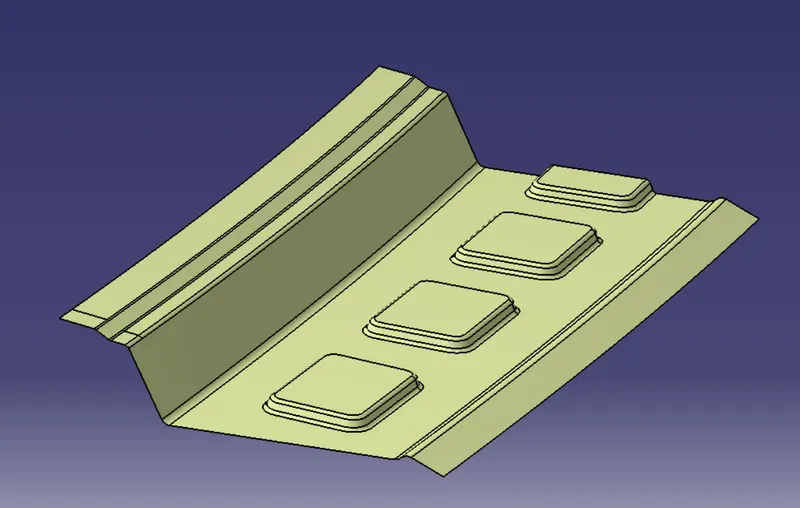
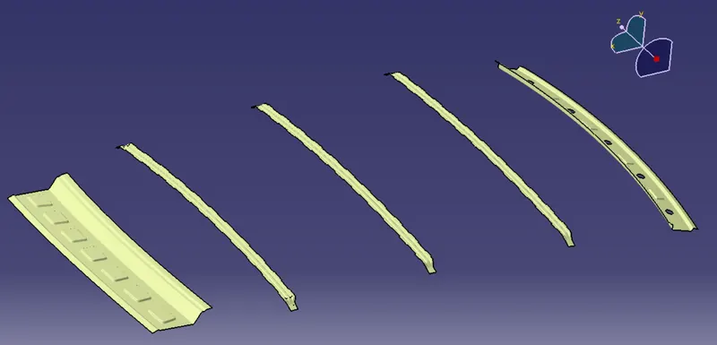
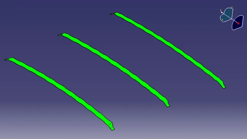
- Bow roofs are used to give strength to the Roof.
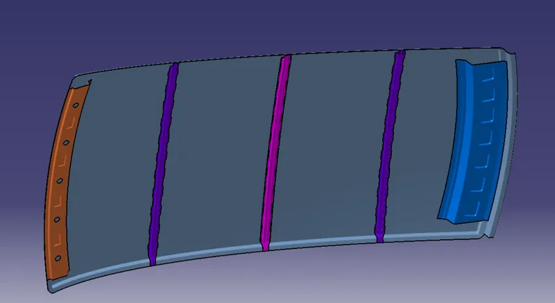
- There are 3 bow roofs created with equal distance between Front and Rear roof rail.
- Bow roofs are created by offsetting the roof surface 5mm, 8mm and 10mm.
- Next use the parallel curve option and project then on the offsets and cut it considering draft angle adn split it with the surfaces.
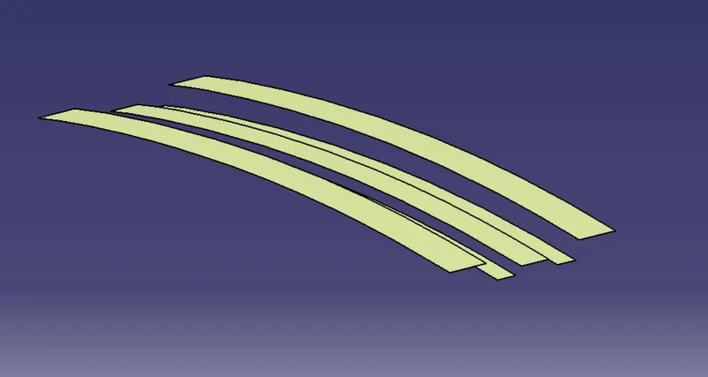
Use multi section surfaces to join the cutted offsets and provide the face fillets to it.
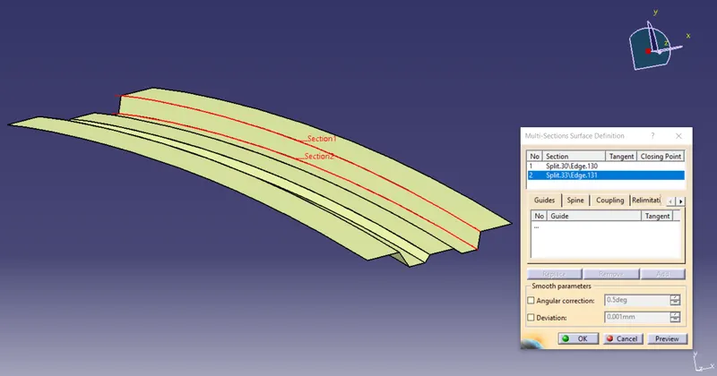
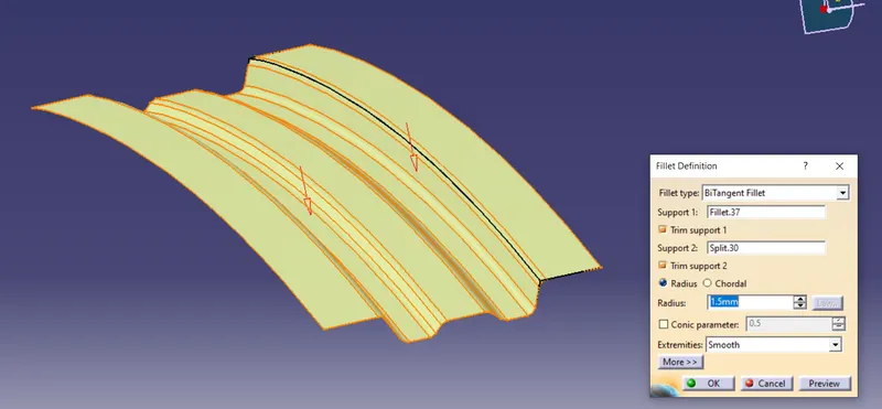
- After creating a bow roof we need to create mastic regions on it.
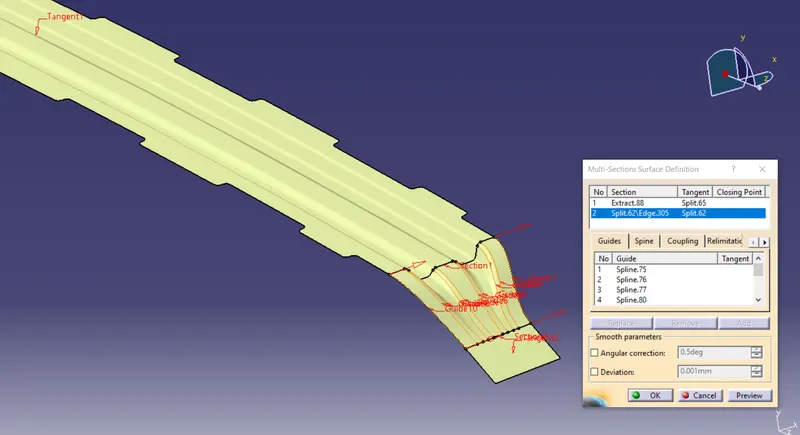
- For that i created a sketch and project on it and split it.
- Then used Multi Sections Surfaces to join it with flange.
Center reinforcement:
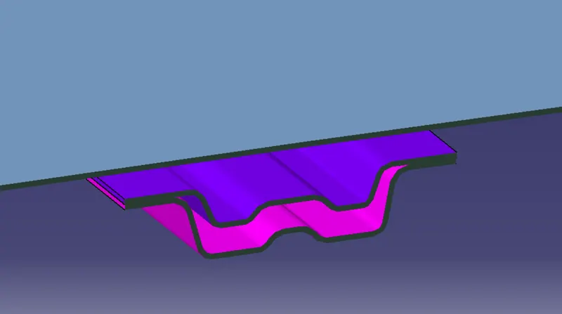
For the center reinforcement follow the same procedure from the bow roof creation with bigger dimensions.
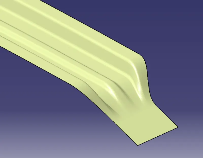
Center reinforcement of the roof is going to be fixed after the bow roof by spot welding.
Creation of solid:
After creating all these surfaces, use the Thicken command and thicken it in proper dimensions in the proper direction.
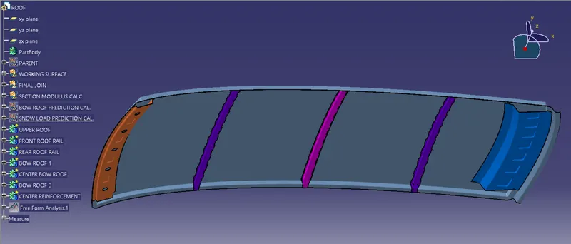
Curvature study on the Roof:
After getting the final body it has to be checked and justify that it passes the standards.
The tests we are done on the Roof are which satisfies the standards and the Bow roof positioning and the Final design are
- Heat distortion
- Snow load
- Roll-over
Here we have tested Heat distortion and Snow load criteria.
Heat distortion criteria:
Heat distortion test is to check the strength of the roof. Heat distortion temperature is when the metal softens and deforms under specific loads.
- To calculate the heat distortion criteria by the bow roof position formula,
- We need to create a sketch , draw a line on the center of the roof on OY axis
- Next draw a line from the center line by a 300mm distance
- After that draw a line from 100mm distance on both sides of the 300mm line
- Then draw a line between the center of roof rails and draw the lines from the center line by the distance of 100mm on both sides.
- Atlast make an intersection on these lines from a coincident line to get points.
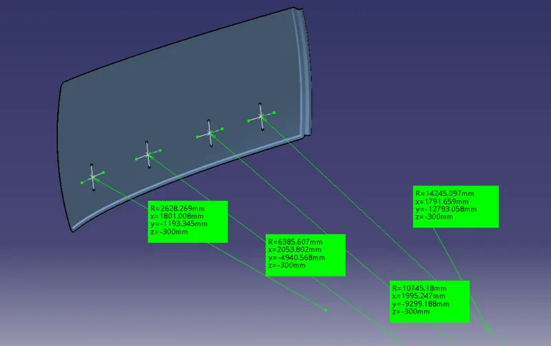
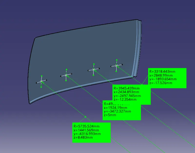
From that point draw a three point arc and measure the Radius of the arc that will be our Rx and Ry values.
W = [1.73 x 10^(-3) x L] + [1.85 x 10^(-8) x (R^2)/t] + [ 1.10x10^(-3) x l] - 2.68
Judgement Condition : OK< 2.7> 3.1
Where
L = Roof Length in X-Direction[mm](Roof dimension in 0-Y)
R = Roof curvature
R = 2(Rx*Ry)/(Rx+Ry)
Rx = X curvature
Ry = Y curvature
t = Roof plate thickness [mm]
l = Bow Roof Span [mm]
| Sr. No. | Bow | L | Rx | Ry | R=2*(Rx*Ry)/(Rx+Ry) | t | l | R^2/t | W | OK / NG |
| 1 | Front rail to Bow 1 | 2117.594 | 5735.524 | 2628.269 | 3604.704212 | 0.75 | 410.238 | 17325190 | 1.76 | OK |
| 2 | Bow 1 To Center rail | 2117.594 | 4925.503 | 6385.607 | 5561.315633 | 0.75 | 465.503 | 41237642 | 2.26 | OK |
| 3 | Bow 2 to Center rail | 2117.594 | 3945.439 | 10745.18 | 5625.34 | 0.75 | 3945.439 | 42192744 | 2.28 | OK |
| 4 | Bow 3 to Rear rail | 2117.594 | 3318.443 | 14245.1 | 5382.917387 | 0.75 | 273.325 | 38634293 | 2.00 | OK |
Snow load criteria:
Snow load test used to verify that roof assembly exhibited no permanent deflection due to distributed load representing snow load.
- To calculate the snow load condition, we have a snow load formula
- To measure the required values
- I created a sketch and draw a line on OY axis from the center if the roof
- From that line draw a parallel line distance of 100mm on both sides
- Then make intersection points of these lines and draw a three point arc
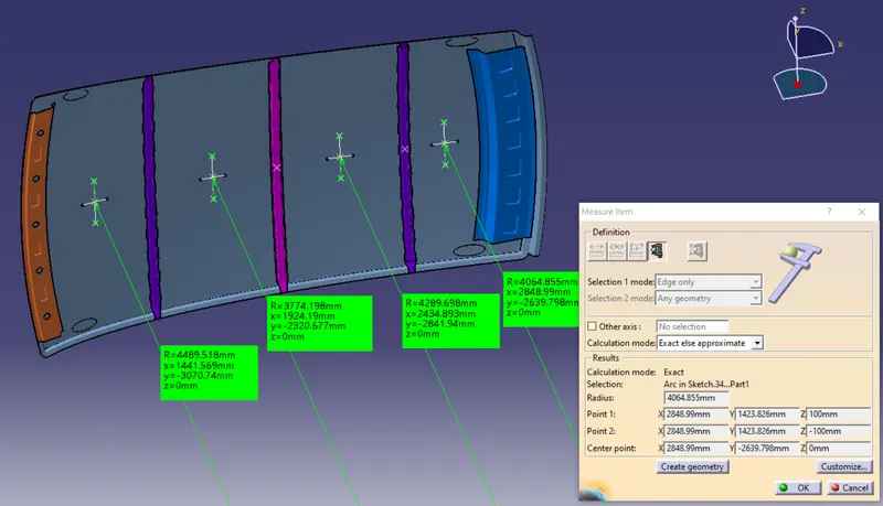
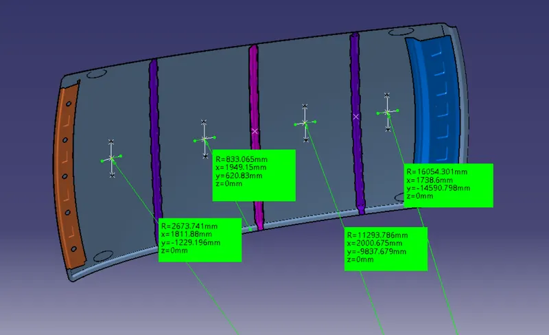
Measure the Radius of the arcs, the arc on the OY axis going to be our Ry and the perpendicular arcs will be Rx.
Qr = [Iy x t2] / [α x s x [(Rx + Ry)/2]2 x 10-8]
Where
α = My x Lx2 x 10-12 , My = Y(Ly-Y)
Judgement condition = Qr ≥ 3.1
250 ≤ s ≤ 380
t = Roof plate thickness [mm]
Ly = Distance between the front and rear roof Rails on the Vehicle along with 0Y[mm]
Length of Roof panel with the center point between Roof rail Front /Rear as the reference point of the front and the rear.
Lx = Distance between the Left and Right end of the roof on the Roof BOW [mm]
Width of the roof panel exposed on the surface.
Y = Distance front Front Roof Rail to Roof BOW[mm]
s = Distance for which Roof BOW bears divided load [mm]
s = L1/2 + L2/2
Iy = Geometrical moment of inertia of Roof BOW (Y cross-section )[mm4]
Rx = Lateral direction curvature radius of roof panel Y cross-section on Roof BOW [mm]
Roof panel curvature Radius of the Length Lx in Front view
Ry = Longitudinal Direction curvature radius of the Roof panel X cross-section on Roof BOW [mm]
Roof panel X curvature radius of length s in Side view
| Sr. No. | Bow | Iy | α | Lx | Ly | y | s | Rx | Ry | t | Qr |
| 1 | Front rail to Bow 1 | 6251.35 | 0.87 | 1110.68 | 1923.11 | 496.938 | 502.695 | 4489.518 | 2673.741 | 0.75 | 62.68 |
| 2 | Bow 1 To Bow 2 | 6448 | 0.83 | 1072.662 | 1923.11 | 510.452 | 510.53 | 3774.198 | 833.065 | 0.75 | 14.098 |
| 3 | Bow 2 to Bow 3 | 6249 | 0.31 | 1052.201 | 1923.11 | 510.605 | 454.71 | 4289.698 | 1129+3.786 | 0.75 | 24.68 |
| 4 | Bow 3 to Rear rail | 1923.11 | 398.82 | 4064.855 | 16054.301 | 0.75 |
Section modulus:
Section modulus formula
S = I/y
S = Section Modulus
I = Moment of Inertia
y = distance between the neutral axis and the extreme end of the object
Front Roof Rail:
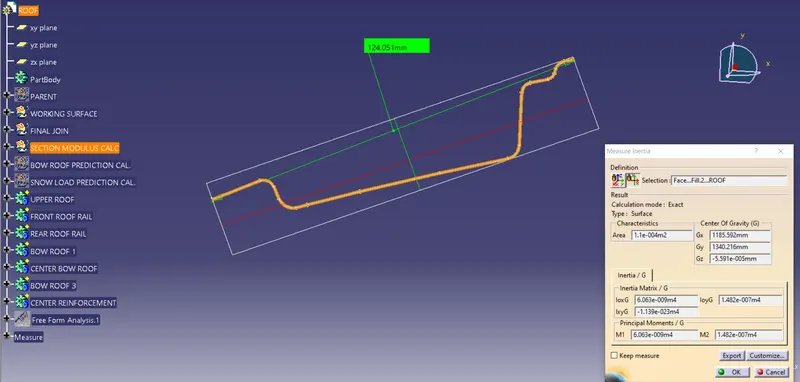
By taking the minimum value from the two value
Unit is converted from meter to millimeter
`M1=146998mm^4`
`Y=124.051/2`
`= 62.0255`m`
putting these values in the formula we have got the section modulus for the hood,
`S=I/Y`
`S=146998/62.0255`
`S=2369.96mm^3`
Rear Roof Rail:
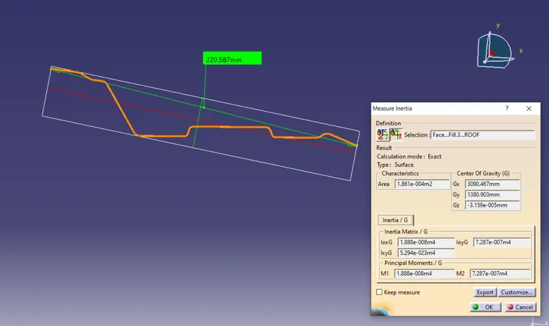
By taking the minimum value from the two value
Unit is converted from meter to millimeter
`M1=728670mm^4`
`Y=220.587/2`
`= 110.2935`m`
putting these values in the formula we have got the section modulus for the hood,
`S=I/Y`
`S=728670/110.2935`
`S=6606.644mm^3`
Bow Roof 1:
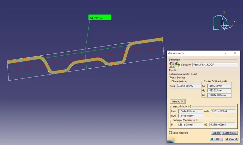
By taking the minimum value from the two value
Unit is converted from meter to millimeter
`M1=6251.35mm^4`
`Y=44.892/2`
`= 22.446`m`
putting these values in the formula we have got the section modulus for the hood,
`S=I/Y`
`S=6251.35/22.446`
`S=278.506mm^3`
Bow Roof 2:
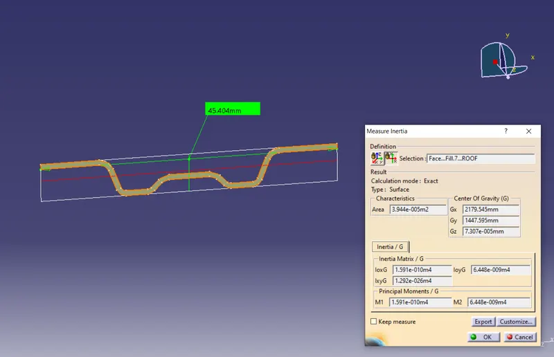
By taking the minimum value from the two value
Unit is converted from meter to millimeter
`M1=6648mm^4`
`Y=45.404/2`
`= 22.702`m`
putting these values in the formula we have got the section modulus for the hood,
`S=I/Y`
`S=6448/22.702`
`S=284.02mm^3`
Bow Roof 3:
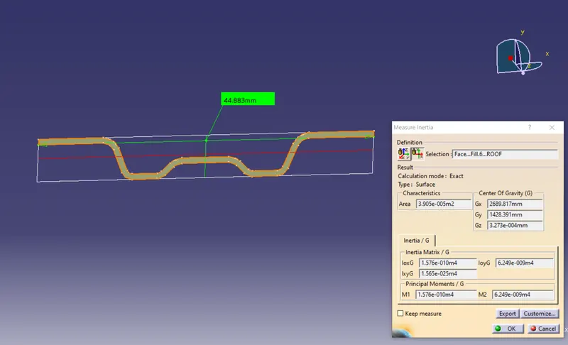
By taking the minimum value from the two value
Unit is converted from meter to millimeter
`M1=6249mm^4`
`Y=44.883/2`
`= 22.4`m`
putting these values in the formula we have got the section modulus for the hood,
`S=I/Y`
`S=6249/22.4`
`S=278.9mm^3`
Center reinforcement & Bow Roof 2:
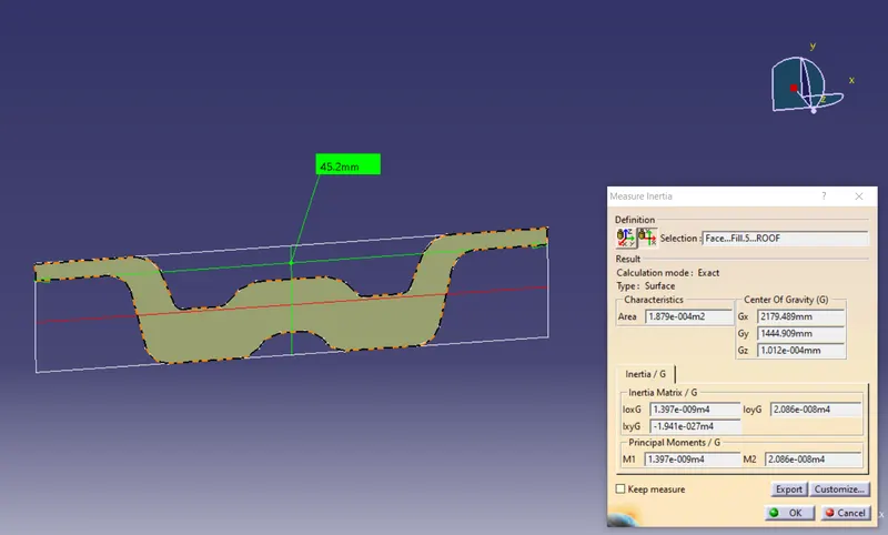
By taking the minimum value from the two value
Unit is converted from meter to millimeter
`M1=20858.3mm^4`
`Y=45.2/2`
`= 22.6`m`
putting these values in the formula we have got the section modulus for the hood,
`S=I/Y`
`S=20858.3/22.6`
`S=922.93mm^3`
| Parts | Moment of Inertia, I(`mm^4`) | Length of the section `(mm)` | Y=Length/2`(mm)` | Section Modulus, S`(mm^3)` |
| Front Roof Rail | 146998 | 124.051 | 62.0255 | 2369.96 |
| Rear Roof Rail | 728670 | 220.587 | 110.2935 | 6606.644 |
| Bow Roof 1 | 6251.35 | 44.9 | 22.45 | 278.506 |
| Bow Roof 2 | 6448 | 45.4 | 22.7 | 284.02 |
| Bow Roof 3 | 6249 | 44.883 | 22.4415 | 278.9 |
| Center reinforcement & Bow Roof 2 | 20858.3 | 45.2 | 22.6 | 922.93 |
Draft Analysis:
Roof:
Front Roof Rail:
Rear Roof Rail:
Bow Roof:
Center reinforcement:
Results:
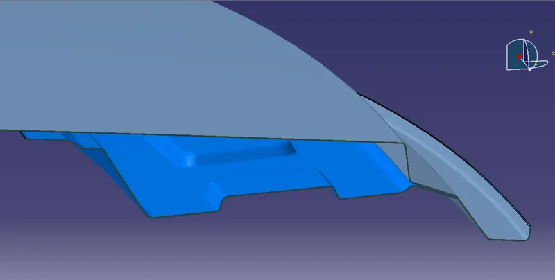
Section View:
Final Model:
Learned Outcome:
- Learned How yo calculate Heat distortion and Snow Load test.
- Learned to create rails with the standards.